EP1114986B1 - Fahrzeugsitz - Google Patents
Fahrzeugsitz Download PDFInfo
- Publication number
- EP1114986B1 EP1114986B1 EP00128012A EP00128012A EP1114986B1 EP 1114986 B1 EP1114986 B1 EP 1114986B1 EP 00128012 A EP00128012 A EP 00128012A EP 00128012 A EP00128012 A EP 00128012A EP 1114986 B1 EP1114986 B1 EP 1114986B1
- Authority
- EP
- European Patent Office
- Prior art keywords
- seat
- load
- child restraint
- restraint apparatus
- detection value
- Prior art date
- Legal status (The legal status is an assumption and is not a legal conclusion. Google has not performed a legal analysis and makes no representation as to the accuracy of the status listed.)
- Expired - Lifetime
Links
- 238000001514 detection method Methods 0.000 claims description 118
- 238000000034 method Methods 0.000 claims description 16
- 238000012790 confirmation Methods 0.000 description 9
- 238000005259 measurement Methods 0.000 description 3
- 238000012545 processing Methods 0.000 description 3
- 238000010586 diagram Methods 0.000 description 2
- 239000003990 capacitor Substances 0.000 description 1
- 230000000452 restraining effect Effects 0.000 description 1
- 238000012546 transfer Methods 0.000 description 1
Images


Classifications
-
- G—PHYSICS
- G01—MEASURING; TESTING
- G01G—WEIGHING
- G01G19/00—Weighing apparatus or methods adapted for special purposes not provided for in the preceding groups
- G01G19/40—Weighing apparatus or methods adapted for special purposes not provided for in the preceding groups with provisions for indicating, recording, or computing price or other quantities dependent on the weight
- G01G19/413—Weighing apparatus or methods adapted for special purposes not provided for in the preceding groups with provisions for indicating, recording, or computing price or other quantities dependent on the weight using electromechanical or electronic computing means
- G01G19/414—Weighing apparatus or methods adapted for special purposes not provided for in the preceding groups with provisions for indicating, recording, or computing price or other quantities dependent on the weight using electromechanical or electronic computing means using electronic computing means only
- G01G19/4142—Weighing apparatus or methods adapted for special purposes not provided for in the preceding groups with provisions for indicating, recording, or computing price or other quantities dependent on the weight using electromechanical or electronic computing means using electronic computing means only for controlling activation of safety devices, e.g. airbag systems
Definitions
- the present invention relates to a vehicle seat according to the preamble of claim 1, which is provided with a load detector, and to a child restraint apparatus detecting method according to the preamble of claim 9.
- a vehicle equipped with an air bag may be provided with load detectors to detect whether a passenger is sitting on a seat.
- the load detectors may also detect the weight of the passenger sitting on the seat to optimally adjust the amount of generated gas when the air bag is inflated.
- JP-No. 11-1153 describes such load sensors.
- a seat is supported on left and right rails, each fixed to the floor of a vehicle by a mount bracket, so that the seat can be moved back and forth along the rails.
- a load sensor is arranged between each rail and the associated mount bracket. The weight of the seat is detected based on load signals generated by the load sensors.
- a child restraint system may be installed on a vehicle seat.
- the restraining force of the seat belt applies a large downward load on the seat. This affects the detection of each load sensor and results in the sensors detecting a weight that is greater than the actual weight of the CRS. As a result, the detection may, for example, erroneously indicate that a passenger is sitting on the seat.
- a vehicle seat that enables detection of a CRS is sought after.
- WO-A-01/18507 which is only relevant for novelty purposes, describes a system for correcting a seat occupant weight measurement error induced by a seat belt in order to control a vehicle airbag.
- a child seat can be detected by capturing measurement values of four load cells positioned on each respective corner of a vehicle seat having the child seat attached thereto. The captured measurement values are used for calculating a compensation factor for the airbag, wherein a degree of asymmetry of the load on the seat is calculated and monitored by a transfer function including several thresholds.
- US-A-5 865 463 shows an airbag deployment controller wherein the values of 4 sensors arranged in a vehicle seat are summed up and compared to a threshold value in order to determine if an infant or an infant in a child seat is placed on the seat, i.e. if an airbag should be turned on or off.
- the present invention provides a seat having the features of claim 1 including a seat belt fastened to an anchor, which is located on one side of a rear portion of the seat.
- the seat includes a first load sensor attached to the seat in the vicinity of the anchor to detect load and generate a first detection value representing the load detected by the first load sensor.
- a second load sensor is attached to the seat at a side opposite to the first load sensor to detect load and generate a second detection value representing the load detected by the second load sensor.
- a control unit is connected to the first and second load sensors. The control unit determines whether a child restraint apparatus is present based on the first and second detection values.
- the present invention also provides a method having the features of claim 9 for detecting whether a child restraint apparatus is fastened to a seat by a seat belt that is fastened to an anchor.
- the anchor is located on one side of a rear portion of the seat.
- the seat includes a first load sensor attached to the seat in the vicinity of the anchor to detect load and generate a first detection value representing the load detected by the first load sensor.
- a second load sensor is attached to the seat at a side opposite to the first load sensor to detect load and generate a second detection value representing the load detected by the second load sensor.
- the method includes comparing the first and second detection values, obtaining a difference between the first and second detection values, comparing the difference with a predetermined rear differential reference value, and determining that the child restraint apparatus is present when the second detection value is greater than the first detection value and the difference is greater than the rear differential reference value.
- a vehicle seat according to a preferred embodiment of the present invention will now be described with reference to Figs. 1 to 6 .
- Fig. 1 is a perspective view showing a vehicle seat 1.
- a base frame 2 which extends in the longitudinal direction of the vehicle (the direction indicated by arrow X), is fixed to the floor (not shown) of the vehicle on each side of the seat 1.
- Front and rear brackets 3 are fixed to each base frame 2.
- a lower support 4 is fixed to each pair of brackets 3.
- the lower support 4 has a U-shaped cross-section and extends parallel to the corresponding base frame 2.
- a slide groove 5 extends longitudinally through each lower support 4.
- Each slide groove 5 receives an upper support 6 so that the upper support 6 can slide along the slide groove 5.
- a front sensor bracket 7 and a rear sensor bracket 8 connect an arm 16 to each upper support 6 such that the arm 16 is spaced from the upper support 6 by a predetermined distance.
- the left and right arms 16 support a seat cushion 9 and a seat back 10.
- each front sensor bracket 7 has an upper end 7a and a lower end 7b.
- a curved deformation portion 7c is defined between the upper and lower ends 7a, 7b.
- the upper end 7a is connected to the front section of the associated arm 16, and the lower end 7b is connected to the front section of the associated upper support 6.
- a right front load sensor 21 is attached to the deformation portion 7c of the right front sensor bracket 7, and a left front load sensor 22 is attached to the deformation portion 7c of the left front sensor bracket 7.
- the left and right front load sensors 21, 22 each include a strain detector, such as a strain gauge. The strain detector electrically detects the degree of deformation of the associated deformation portion 7c relative to the load applied to the seat cushion 9.
- each rear sensor bracket 8 has an upper end 8a and a lower end 8b.
- a curved deformation portion 8c is defined between the upper and lower ends 8a, 8b.
- the upper end 8a is connected to the rear section of the associated arm 16, and the lower end 8b is connected to the rear section of the associated upper support 6.
- a right rear load sensor 23 is attached to the deformation portion 8c of the right rear sensor bracket 8.
- a left rear load sensor 24 is attached to the deformation portion 8c of the left rear sensor bracket 8.
- the left and right rear load sensors 23, 24 each include a strain detector, such as a strain gauge. The strain detector electrically detects the degree of deformation of the associated deformation portion 8c according to the load applied to the seat cushion 9.
- a belt anchor 12 and an anchor bracket 13 are connected to one of the upper supports 6 (the left upper support 6 in Fig. 1 ).
- a seat belt 11 is fastened to the belt anchor 12.
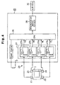
- Fig. 4 is a block diagram showing the electric structure of a seat load detector 20.
- the load detector 20 includes the load sensors 21, 22, 23, 24 and an electronic control unit (ECU) 25.
- the ECU 25 has a central processing unit (CPU) 26, a sensor signal input circuit 27, and a determination output circuit 28.
- CPU central processing unit
- the sensor signal input circuit 27 includes active filters 27a, 27b, 27c, 27d that are associated with the load sensors 21, 22, 23, 24, respectively.
- the sensors 21, 22, 23, 24 generate load signals provided to the CPU 26 via the associated active filters 27a, 27b, 27c, 27d.
- Each of the active filters 27a-27d is a known low-pass filter.
- a low-pass filter is configured, for example, by combining a passive element, which includes a capacitor and a resistor, with an active element, which includes an amplifier.
- the active filters 27a, 27b, 27c, 27d pass only low frequency signals and eliminate other signals.
- Front detection values FR, FL are obtained from the load signals of the right and left front load sensors 21, 22 that pass through the active filters 27a, 27b.
- a rear-right detection value RR is obtained from the load signal of the right rear load sensor 23 that passes through the active filter 27c, and a rear-left detection value RL is obtained from the load signal of the left rear load sensor 24 that passes through the active filter 27d.
- the CPU 26 performs various operations, which are based on prestored control programs and initial data, and provides operational results to the determination output circuit 28.
- a child restraint seat (CRS) 31 may be installed on the seat 1.
- the CRS 31 is fastened to the seat 1 by the seat belt 11.
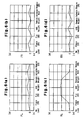
- Figs. 6(a), 6(b), 6(c), 6(d) respectively show the behavior of the detections values FL, FR, RL, RR (as confirmed by the inventors) when using the CRS 31.
- Figs. 6(a) to 6(d) each show the corresponding detection values FL, FR, RL, RR in seven different states.
- the CRS 31 is placed on the seat 1 in the second state and fastened to the seat 1 by the seat belt 11 in the third state.
- a weight of, for example, 18 kilograms is added to the CRS 31 to simulate a child sitting on the CRS 31 in the fourth state.
- the weight is removed from the CRS 31 in the fifth state.
- the seat belt 11 is unfastened in the sixth state, and the CRS 31 is removed from the seat 1 in the seventh state.
- the rear-left detection value RL which represents the load applied to the rear portion of the seat 1 at the side opposite to the belt anchor 12, varies significantly. Accordingly, the CRS 31 may be detected by comparing the rear-right detection value RR of the right rear load sensor 23 and the rear-left detection value RL of the left rear load sensor 24.
- the right and left rear load sensors 23, 24 are connected to the rear portion of the seat 1 under substantially the same conditions. Further, the rear-left detection value RL increases significantly when installing the CRS 31.
- the rear-left detection value RL when installing the CRS 31, the rear-left detection value RL, the sum of the first to front detection values RR, RL, FR, FL, and the sum of the first and rear-left detections values RR, RL increase.
- the rear-right detection value RR varies within a relatively narrow range when installing the CRS 31.
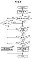
- the CRS 31 is detected based on the behavior of the detection values RR, RL, FR, FL through a routine illustrated in the flowchart of Fig. 5 .
- the routine is performed in interrupts at predetermined time intervals.
- the CPU 26 When entering the routine, at step 101, the CPU 26 reads the four detection values RR, RL, FR, FL. At step 102, the CPU 26 determines whether or not the sum of the four detection values RR, RL, FR, FL is greater than or equal to a predetermined value A (total sum reference value).
- the predetermined value A is set at a value that permits confirmation of a significant increase in the sum of the four detection values RR, RL, FR, FL when the CRS 31 is installed.
- the CPU 26 determines that the sum of all four detection values RR, RL, FR, FL is greater than or equal to the predetermined value A, the CPU 26 proceeds to step 103. If the CPU 26 determines that the sum of all four detection values RR, RL, FR, FL is less than the predetermined value A, the CPU 26 proceeds to step 104 to further determine whether or not the sum of the first and rear-left detection values RR, RL is greater than or equal to a predetermined value B (rear sum reference value).
- the predetermined value B is set at a value that permits confirmation of a significant increase in the sum of the rear detection values RR, RL when the CRS 31 is installed.
- step 103 the CPU 26 proceeds to step 103 when the sum of all four values RR, RL, FR, FL is greater than or equal to the predetermined value A or when the sum of the rear detection values RR, RL is greater than or equal to the predetermined value B.
- the CPU 26 determines whether or not the rear-left detection value RL is greater than the rear-right detection value RR and whether the difference between the rear-left detection value RL and the rear-right detection value RR is greater than or equal to a predetermined value C (rear differential reference value).
- the predetermined value C is set at a value that permits confirmation of a significant increase in the difference between the rear-left detection value RL and the rear-right detection value RR when the CRS 31 is installed. If the CPU 26 determines that the rear-left detection value RL is greater than the rear-right detection value RR and that the difference between the rear-left detection value RL and the rear-right detection value RR is greater than or equal to the predetermined value C, the CPU 26 proceeds to step 105.
- the CPU 26 determines whether or not the rear-left detection value RL is greater than or equal to a predetermined value D (first reference value).
- the predetermined value D is set at value that permits confirmation of a significant increase in the rear-left detection value RL when the CRS 31 is installed. If the CPU 26 determines that the rear-left detection value RL is greater than or equal to the predetermined value D, the CPU 26 proceeds to step 106.
- the CPU 26 determines whether the rear-right detection value RR is less than or equal to a predetermined value E (second reference value).
- the predetermined value E is set at a value that permits confirmation of a significant decrease in the rear-right detection value RR when the CRS 31 is installed. If the CPU 26 determines that the rear-right detection value RR is less than or equal to the predetermined value E, the CPU 26 determines that the CRS 31 is installed and proceeds to step 107.
- step 107 the CPU 26 sends a signal indicating that the CRS 31 is installed to, for example, an air bag ECU 30 through the determination output circuit 28.
- the CPU 26 then temporarily terminates subsequent processing. If a condition set in any one of steps 103 to 106 is not satisfied, the CPU 26 determines that the CRS 31 is not installed and proceeds to step 108.
- the CPU 26 determines that the CRS 31 is not installed and obtains the load applied to the seat 1 (i.e., the weight of the passenger if one is sitting on the seat 1) based on, for example, the sum of the four detection values RR, RL, FR, FL. The CPU 26 then provides the result to, for example, the air bag ECU 30 via the determination output circuit 28. Afterward, the CPU 26 temporarily terminates subsequent processing.
- the air bag ECU 30 optimally controls the operation of an air bag based on the results provided by the CPU 26. The advantages described below are obtained by the preferred embodiment.
- the shape of the front and rear sensor brackets 7, 8 illustrated in Figs. 3(a) and 3(b) may be changed when necessary as long as they strain in accordance with the weight applied to the seat 1.
- the locations of the load sensors 21-24 may be changed as long as they permit detection of the weight applied to the seat 1.
- Two load sensors (the right and left front load sensors 21, 22) are employed as the front load sensors. However, additional load sensors may be used for the front load sensors.
- the right and left front load sensors 21, 22 may be omitted. In this case, the detection of the CRS 31 based on the sum of the four detection values RR, RL, FR, FL (step 102) is eliminated. This would reduce the number of load sensors and save costs.
- the other conditions may be omitted.
- the ratio between the rear-left detection value RL and the rear-right detection value RR may be evaluated to determine whether the CRS 31 is installed.
- FIG. 5 show a seat designed for the left side of a vehicle
- the present invention may be applied to a seat arranged on either side of a vehicle as long as the seat has a structure enabling detection of the CRS 31. If the seat is located on the right side of the vehicle, the signals designated in the routine of Fig. 5 are changed accordingly.
Landscapes
- Physics & Mathematics (AREA)
- Engineering & Computer Science (AREA)
- Mathematical Physics (AREA)
- Theoretical Computer Science (AREA)
- General Physics & Mathematics (AREA)
- Seats For Vehicles (AREA)
- Air Bags (AREA)
- Passenger Equipment (AREA)
Claims (16)
- Sitz (1) mit einer Kinderhaltevorrichtungserfassungseinrichtung, wobei der Sitz Folgendes aufweist
einen Sitzgurt (11), der an einer Verankerung (12) befestigt ist, wobei sich die Verankerung (12) auf einer Seite eines hinteren Abschnitts des Sitzes (1) befindet,
einen hinten rechts/hinten links angeordneten, ersten Lastsensor (23), der an dem Sitz (1) in der Nähe der Verankerung (12) angebracht ist, um eine Last zu erfassen und einen ersten Erfassungswert (RR) zu erzeugen, der die durch den ersten Lastsensor (23) erfasste Last wiedergibt,
einen hinten links/hinten rechts angeordneten, zweiten Lastsensor (24), der an dem Sitz (1) an einer dem ersten Lastsensor (23) gegenüberliegenden Seite angebracht ist, um eine Last zu erfassen und einen zweiten Erfassungswert (RL) zu erzeugen, der die durch den zweiten Lastsensor (24) erfasste Last wiedergibt, und
einer Steuereinheit (25), die mit dem ersten und dem zweiten Lastsensor (23, 24) verbunden ist,
dadurch gekennzeichnet, dass
die Steuereinheit (25) angepasst ist, um den ersten und den zweiten Erfassungswert (RR, RL) zu vergleichen, einen Unterschied (RL - RR) zwischen dem ersten und dem zweiten Erfassungswert (RR, RL) zu erhalten, den Unterschied (RL - RR) mit einem vorbestimmten Referenzwert (C) des hinteren Unterschieds zu vergleichen, und dann festzustellen, dass eine Kinderhaltevorrichtung (31) durch den Sitzgurt (11) an dem Sitz (1) befestigt ist, wenn der zweite Erfassungswert (RL) größer als der erste Erfassungswert (RR) und der Unterschied (RL - RR) größer als der Referenzwert (C) des hinteren Unterschieds ist. - Sitz (1) mit einer Kinderhaltevorrichtungserfassungseinrichtung nach Anspruch 1, dadurch gekennzeichnet, dass die Steuereinheit (25) den ersten und den zweiten Erfassungswert (RR, RL) zusammenrechnet, um eine Summe (RR + RL) der hinteren Lasten zu erhalten und die Summe (RR + RL) der hinteren Lasten mit einem vorbestimmten Referenzwert (B) der hinteren Summe vergleicht, um zu bestimmen, ob die Kinderhaltevorrichtung (31) durch den Sitzgurt (11) an dem Sitz (1) befestigt ist.
- Sitz (1) mit einer Kinderhaltevorrichtungserfassungseinrichtung nach einem der Ansprüche 1 und 2, der des Weiteren dadurch gekennzeichnet ist, dass er Folgendes aufweist
einen dritten Lastsensor (21), der mit der Steuereinheit (25) verbunden ist und an dem Sitz dem ersten Lastsensor (23) vorgelagert angebracht ist, um eine Last zu erfassen und einen dritten Erfassungswert (FR) zu erzeugen, der die durch den dritten Lastsensor (21) erfasste Last wiedergibt, und
einen vierten Lastsensor (22), der mit der Steuereinheit (25) verbunden ist und an dem Sitz (1) dem zweiten Lastsensor (24) vorgelagert angebracht ist, um eine Last zu erfassen und einen vierten Erfassungswert (FL) zu erzeugen, der die durch den vierten Lastsensor (22) erfasste Last wiedergibt,
wobei die Steuereinheit (25) den ersten, den zweiten, den dritten und den vierten Erfassungswert (RR, RL, FR, FL) zusammenrechnet, um eine Gesamtlastsumme (RR
+ RL + FR + FL) zu erhalten, und die Gesamtlastsumme (RR + RL + FR + FL) mit einem vorbestimmten Gesamtsummenreferenzwert (A) vergleicht, um zu bestimmen, ob die Kinderhaltevorrichtung (31) durch den Sitzgurt (11) an dem Sitz (1) befestigt ist. - Sitz (1) mit einer Kinderhaltevorrichtungserfassungseinrichtung nach Anspruch 3, dadurch gekennzeichnet, dass die Steuereinheit (25) dann bestimmt, dass die Kinderhaltevorrichtung (31) durch den Sitzgurt (11) an dem Sitz (1) befestigt ist, wenn wenigstens eine von der Summe der hinteren Lasten und der Gesamtlastsumme (RR + RL; RR + RL + FR + FL) größer als der dazugehörige Referenzwert (B, A) ist.
- Sitz (1) mit einer Kinderhaltevorrichtungserfassungseinrichtung nach einem der Ansprüche 1 bis 4, dadurch gekennzeichnet, dass die Steuereinheit (25) den zweiten Erfassungswert (RL) mit einem vorbestimmten ersten Referenzwert (D) vergleicht, und dann bestimmt, dass die Kinderhaltevorrichtung (31) durch den Sitzgurt (11) an dem Sitz (1) befestigt ist, wenn der zweite Erfassungswert (RL) größer als der erste Referenzwert (D) ist.
- Sitz (1) mit einer Kinderhaltevorrichtungserfassungseinrichtung nach einem der Ansprüche 1 bis 5, dadurch gekennzeichnet, dass die Steuereinheit (25) den ersten Erfassungswert (RR) mit einem zweiten Referenzwert vergleicht und dann bestimmt, dass die Kinderhaltevorrichtung (31) durch den Sitzgurt (11) an dem Sitz (1) befestigt ist, wenn der erste Erfassungswert (RR) kleiner als der zweite Referenzwert (E) ist.
- Sitz (1) mit einer Kinderhaltevorrichtungserfassungseinrichtung nach einem der vorangehenden Ansprüche, dadurch gekennzeichnet, dass die Steuereinheit (25) ein Verhältnis des ersten und des zweiten Erfassungswerts (RR, RL) berechnet und dann bestimmt, dass die Kinderhaltevorrichtung (31) durch den Sitzgurt (11) an dem Sitz (1) befestigt ist, wenn der zweite Erfassungswert (RL) größer als der erste Erfassungswert (RR) ist und das Verhältnis eine vorbestimmte Bedingung erfüllt.
- Sitz (1) mit einer Kinderhaltevorrichtungserfassungseinrichtung nach einem der vorangehenden Ansprüche, dadurch gekennzeichnet, dass die Steuereinheit (25) einen Betrieb eines Airbags in Übereinstimmung damit steuert, ob die Kinderhaltevorrichtung (31) durch den Sitzgurt (11) an dem Sitz (1) befestigt ist.
- Verfahren zum Erfassen, ob einer Kinderhaltevorrichtung (31) durch einen an einer Verankerung (12) befestigten Sitzgurt (11) an einem Sitz (1) befestigt ist, wobei sich die Verankerung (12) auf einer Seite eines hinteren Abschnitts des Sitzes (1) befindet, wobei der Sitz (1) eine Kinderhaltevorrichtungserfassungseinrichtung aufweist, die einen hinten rechts angeordneten, ersten Lastsensor (23), der an dem Sitz (1) in der Nähe der Verankerung (12) angebracht ist, um eine Last zu erfassen und einen ersten Erfassungswert (RR) zu erzeugen, der die durch den ersten Lastsensor (23) erfasste Last wiedergibt, und einen hinten links angeordneten, zweiten Lastsensor (24) aufweist, der an dem Sitz (1) auf einer dem ersten Lastsensor (23) gegenüberliegenden Seite angebracht ist, um eine Last zu erfassen und einen zweiten Erfassungswert (RL) zu erzeugen, der die durch den zweiten Lastsensor (24) erfasste Last wiedergibt, wobei das Verfahren den folgenden Schritt aufweist:Vergleichen des ersten und zweiten Erfassungswerts (RR, RL),dadurch gekennzeichnet, dass das Verfahren des Weiteren die folgenden Schritte aufweist:Erhalten eines Unterschieds (RL - RR) zwischen dem ersten und dem zweiten Erfassungswert (RR, RL); Vergleichen des Unterschieds (RL - RR) mit einem vorbestimmten Referenzwert (C) des hinteren Unterschieds; undBestimmen, dass die Kinderhaltevorrichtung (31) durch einen Sitzgurt (11) an dem Sitz (1) befestigt ist, wenn der zweite Erfassungswert (RL) größer als der erste Erfassungswert (RR) und der Unterschied (RL - RR) größer als der Referenzwert (C) des hinteren Unterschieds ist.
- Verfahren nach Anspruch 9, des Weiteren gekennzeichnet durch:Zusammenrechnen des ersten und des zweiten Erfassungswerts (RR, RL), um eine Summe (RR + RL) der hinteren Last zu erhalten;Vergleichen der Summe (RR + RL) der hinteren Lasten mit einem vorbestimmten Referenzwert (B) der hinteren Summe; undBestimmen, dass die Kinderhaltevorrichtung (31) durch einen Sitzgurt (11) an dem Sitz (1) befestigt ist, wenn die Summe (RR + RL) der hinteren Lasten größer als der vorbestimmte Referenzwert (B) der hinteren Summe ist.
- Verfahren nach einem der Ansprüche 9 und 10, wobei die Kinderhaltevorrichtungserfassungseinrichtung des Sitzes (1) des Weiteren einen dritten Lastsensor (21), der mit der Steuereinheit (25) verbunden ist und an dem Sitz (1) dem ersten Lastsensor (23) vorgelagert angebracht ist, um eine Last zu erfassen und einen dritten Erfassungswert (FR) zu erzeugen, der die durch den dritten Lastsensor (21) erfasste Last wiedergibt, und einen vierten Lastsensor (22) aufweist, der mit der Steuereinheit (25) verbunden ist und an einem Sitz (1) dem zweiten Lastsensor (24) vorgelagert angebracht ist, um eine Last zu erfassen und einen vierten Erfassungswert (FL) zu erzeugen, der die durch den vierten Lastsensor (22) erfasste Last wiedergibt, wobei das Verfahren des Weiteren gekennzeichnet ist durch:Zusammenrechnen des ersten, des zweiten, des dritten und des vierten Erfassungswerts (RR, RL, FR, FL), um eine Gesamtlastsumme (RR + RL + FR + FL) zu erhalten;Vergleichen der Gesamtlastsumme (RR + RL + FR + FL) mit einem vorbestimmten Gesamtsummenreferenzwert (A); undBestimmen, dass die Kinderhaltevorrichtung (31) durch den Sitzgurt (11) an dem Sitz (1) befestigt ist, wenn die Gesamtlastsumme (RR + RL + FR + FL) größer als der vorbestimmte Gesamtsummenreferenzwert (A) ist.
- Verfahren nach einem der Ansprüche 10 und 11, das des Weiteren gekennzeichnet ist durch:Bestimmen, dass die Kinderhaltevorrichtung (31) durch den Sitzgurt (11) an dem Sitz (1) befestigt ist, wenn wenigstens einer von der Summe (RR + RL) der hinteren Lasten und der Gesamtlastsumme (RR + RL + FR + FL) größer als der dazugehörige vorbestimmte Schwellenwert (B, A) ist.
- Verfahren nach einem der Ansprüche 9 bis 12, das des Weiteren gekennzeichnet ist durch:Vergleichen des zweiten Erfassungswerts (RL) mit einem vorbestimmten ersten Referenzwert (D); undBestimmen, dass die Kinderhaltevorrichtung (31) durch den Sitzgurt (11) an dem Sitz (1) befestigt ist, wenn der zweite Erfassungswert (RL) größer als der erste Referenzwert (D) ist.
- Verfahren nach einem der Ansprüche 9 bis 13, das des Weiteren gekennzeichnet ist durch:Vergleichen des ersten Erfassungswerts (RR) mit einem vorbestimmten zweiten Referenzwert (E); undBestimmen, dass die Kinderhaltevorrichtung (31) durch den Sitzgurt (11) an dem Sitz (1) befestigt ist, wenn der erste Erfassungswert (RR) kleiner als der zweite Referenzwert (E) ist.
- Verfahren nach einem der Ansprüche 9 bis 14, das des Weiteren gekennzeichnet ist durch:Berechnen eines Verhältnisses des ersten und des zweiten Erfassungswerts (RR, RL); undBestimmen, dass die Kinderhaltevorrichtung (31) durch den Sitzgurt (11) an dem Sitz (1) befestigt ist, wenn der zweite Erfassungswert (RL) größer als der Referenzwert des hinteren Unterschieds ist und das Verhältnis eine vorbestimmte Bedingung erfüllt.
- Verfahren nach einem der Ansprüche 9 bis 15, das des Weiteren gekennzeichnet ist durch Steuern eines Betriebs eines Airbags in Übereinstimmung damit, ob die Kinderhaltevorrichtung (31) durch den Sitzgurt (11) an dem Sitz (1) befestigt ist.
Applications Claiming Priority (2)
| Application Number | Priority Date | Filing Date | Title |
|---|---|---|---|
| JP36674599A JP4185640B2 (ja) | 1999-12-24 | 1999-12-24 | 車両用シート |
| JP36674599 | 1999-12-24 |
Publications (3)
| Publication Number | Publication Date |
|---|---|
| EP1114986A2 EP1114986A2 (de) | 2001-07-11 |
| EP1114986A3 EP1114986A3 (de) | 2002-10-16 |
| EP1114986B1 true EP1114986B1 (de) | 2010-04-21 |
Family
ID=18487566
Family Applications (1)
| Application Number | Title | Priority Date | Filing Date |
|---|---|---|---|
| EP00128012A Expired - Lifetime EP1114986B1 (de) | 1999-12-24 | 2000-12-20 | Fahrzeugsitz |
Country Status (4)
| Country | Link |
|---|---|
| US (1) | US6467804B2 (de) |
| EP (1) | EP1114986B1 (de) |
| JP (1) | JP4185640B2 (de) |
| DE (1) | DE60044234D1 (de) |
Families Citing this family (29)
| Publication number | Priority date | Publication date | Assignee | Title |
|---|---|---|---|---|
| US6653577B2 (en) * | 1995-06-07 | 2003-11-25 | Automotive Technologies | Apparatus and method for measuring weight of an occupying item of a seat |
| US20070135982A1 (en) | 1995-06-07 | 2007-06-14 | Automotive Technologies International, Inc. | Methods for Sensing Weight of an Occupying Item in a Vehicular Seat |
| US6825765B2 (en) * | 1998-12-30 | 2004-11-30 | Automotive Systems Laboratory, Inc. | Occupant detection system |
| US6786104B1 (en) * | 1999-11-04 | 2004-09-07 | Takata Corporation | Seat weight measuring apparatus |
| JP3686330B2 (ja) * | 2000-12-12 | 2005-08-24 | アイシン精機株式会社 | 車両用シート |
| JP2002333366A (ja) * | 2001-05-08 | 2002-11-22 | Aisin Seiki Co Ltd | 乗員判定装置 |
| JP3753083B2 (ja) * | 2001-06-27 | 2006-03-08 | 株式会社デンソー | 着席状態検知装置 |
| JP2003040078A (ja) * | 2001-08-01 | 2003-02-13 | Denso Corp | エアバッグ作動制御システム |
| US6918458B2 (en) * | 2001-10-12 | 2005-07-19 | Autoliv Asp, Inc. | Load management system and method for motor vehicle restraints |
| GB0302690D0 (en) * | 2003-02-06 | 2003-03-12 | Snapwatch Ltd | Display apparatus |
| US20050055180A1 (en) * | 2003-09-08 | 2005-03-10 | Pischke Gina C. | Method and system for seat placement |
| US7194391B2 (en) * | 2003-09-30 | 2007-03-20 | The Boeing Company | Method and system for seat placement |
| JP4279108B2 (ja) * | 2003-09-30 | 2009-06-17 | タカタ株式会社 | 座席上の物体の状態の判別装置 |
| JP3844251B2 (ja) * | 2004-01-16 | 2006-11-08 | 株式会社デンソー | 乗員検知装置 |
| EP1559617B1 (de) * | 2004-01-28 | 2006-11-02 | Aisin Seiki Kabushiki Kaisha | Vorrichtung zur Erfassung der Sitzbelastung |
| JP4878145B2 (ja) * | 2005-02-16 | 2012-02-15 | カルソニックカンセイ株式会社 | 車両用乗員検知装置 |
| JP4942997B2 (ja) * | 2005-12-22 | 2012-05-30 | カルソニックカンセイ株式会社 | 車両用乗員検知装置 |
| JP5019099B2 (ja) * | 2006-08-30 | 2012-09-05 | アイシン精機株式会社 | 車両用シートの乗員判別装置 |
| JP4864678B2 (ja) * | 2006-12-13 | 2012-02-01 | カルソニックカンセイ株式会社 | サイドエアバック制御装置 |
| KR100837919B1 (ko) * | 2007-06-14 | 2008-06-13 | 기아자동차주식회사 | 자동차 시트의 승객판별장치 및 방법 |
| JP2008168903A (ja) * | 2008-03-24 | 2008-07-24 | Furukawa Electric Co Ltd:The | 判別方法 |
| KR101054779B1 (ko) * | 2008-12-02 | 2011-08-05 | 기아자동차주식회사 | 무게 센서를 이용하는 차량의 승객 식별 시스템 |
| US9854995B2 (en) * | 2009-06-05 | 2018-01-02 | Toyota Motor Engineering & Manufacturing North America, Inc. | Non-invasive, non contact system, electronic control unit, and associated methodology for minimizing muscle stress and improving circulation |
| JP5531471B2 (ja) * | 2009-07-07 | 2014-06-25 | アイシン精機株式会社 | 着座判定装置および着座判定方法 |
| JP5589694B2 (ja) * | 2009-10-22 | 2014-09-17 | アイシン精機株式会社 | 着座判定装置および着座判定方法 |
| JP5699816B2 (ja) * | 2011-06-07 | 2015-04-15 | アイシン精機株式会社 | シート乗員判定装置および判定方法 |
| JP5842662B2 (ja) * | 2012-02-22 | 2016-01-13 | アイシン精機株式会社 | シート乗員判定装置 |
| JP5884546B2 (ja) * | 2012-02-22 | 2016-03-15 | アイシン精機株式会社 | シート乗員判定装置 |
| US9409648B2 (en) * | 2014-05-15 | 2016-08-09 | The Boeing Company | Seating arrangement and method |
Family Cites Families (15)
| Publication number | Priority date | Publication date | Assignee | Title |
|---|---|---|---|---|
| ATE183154T1 (de) * | 1994-10-17 | 1999-08-15 | Iee Sarl | Verfahren und vorrichtung zur erfassung gewisser parameter eines kindersitzes zur steuerung eines kraftfahrzeug-gassacks |
| US5474327A (en) | 1995-01-10 | 1995-12-12 | Delco Electronics Corporation | Vehicle occupant restraint with seat pressure sensor |
| US5732375A (en) * | 1995-12-01 | 1998-03-24 | Delco Electronics Corp. | Method of inhibiting or allowing airbag deployment |
| WO1998030413A1 (fr) * | 1997-01-13 | 1998-07-16 | Furukawa Electric Co., Ltd. | Siege equipe d'un detecteur d'assise, detecteur d'assise et dispositif a coussin gonflable de securite |
| US5739757A (en) | 1997-01-30 | 1998-04-14 | Breed Automotive Technology, Inc. | Vehicle passenger weight sensor |
| US5865463A (en) | 1997-02-15 | 1999-02-02 | Breed Automotive Technology, Inc. | Airbag deployment controller |
| JP4079479B2 (ja) | 1997-06-13 | 2008-04-23 | タカタ株式会社 | 車両のシート装置及びエアバッグ装置 |
| KR20010031876A (ko) * | 1997-11-12 | 2001-04-16 | 웰스 러셀 씨 | 차량 좌석 착석 승객의 중량과 위치를 결정하는 방법 및시스템 |
| JP3685475B2 (ja) | 1998-03-26 | 2005-08-17 | タカタ株式会社 | シート重量計測装置 |
| JP3655745B2 (ja) | 1998-04-16 | 2005-06-02 | タカタ株式会社 | シート重量計測装置 |
| US6099032A (en) * | 1998-08-03 | 2000-08-08 | Ford Global Technologies, Inc. | Seat weight sensor system for controlling a vehicle restraining device |
| JP3838794B2 (ja) * | 1998-10-20 | 2006-10-25 | タカタ株式会社 | 乗員拘束装置 |
| US6199902B1 (en) * | 1999-02-12 | 2001-03-13 | Trw Inc. | Apparatus and method for discerning at least one occupant characteristic via absorption of an energy signal |
| DE60004536T2 (de) | 1999-09-10 | 2004-06-24 | Siemens Vdo Automotive Corp., Auburn Hills | Verfahren und vorrichtung zum erfassen des gewichts des benutzers eines sitzes |
| US6282473B1 (en) * | 1999-12-07 | 2001-08-28 | Trw Vehicle Safety Systems Inc. | System and method for controlling a vehicle occupant protection device |
-
1999
- 1999-12-24 JP JP36674599A patent/JP4185640B2/ja not_active Expired - Lifetime
-
2000
- 2000-12-20 EP EP00128012A patent/EP1114986B1/de not_active Expired - Lifetime
- 2000-12-20 DE DE60044234T patent/DE60044234D1/de not_active Expired - Lifetime
- 2000-12-21 US US09/740,869 patent/US6467804B2/en not_active Expired - Lifetime
Also Published As
| Publication number | Publication date |
|---|---|
| EP1114986A3 (de) | 2002-10-16 |
| EP1114986A2 (de) | 2001-07-11 |
| US6467804B2 (en) | 2002-10-22 |
| JP4185640B2 (ja) | 2008-11-26 |
| US20010005074A1 (en) | 2001-06-28 |
| JP2001180355A (ja) | 2001-07-03 |
| DE60044234D1 (de) | 2010-06-02 |
Similar Documents
| Publication | Publication Date | Title |
|---|---|---|
| US6467804B2 (en) | Vehicle seat | |
| EP1028867B1 (de) | Verfahren und system zum bestimmen des gewichts und der position eines fahrzeuginsassen | |
| US7048085B2 (en) | Weight classification system | |
| US6810984B2 (en) | Occupant judging apparatus | |
| EP1190916B1 (de) | Gewichtserkennung für einen Fahrzeugzitz | |
| US6836715B2 (en) | Vehicle seat | |
| US6689960B2 (en) | Seat weight measuring apparatus which determines the weight value based on a value other than the adder output when sensor output exceeds a predetermined value | |
| KR20020029778A (ko) | 시트 착석자 중량을 측정하기 위한 방법 및 장치 | |
| US6774804B2 (en) | Passenger determination device | |
| EP1574401B1 (de) | Verfahren zur Klassifizierung von einem Insassen bei Erfassung des auf dem Sitz befindlichen Gewichts | |
| US6987226B2 (en) | Occupant weight detecting apparatus | |
| US20040135697A1 (en) | Occupant determining device | |
| US7216894B2 (en) | Occupant determination device | |
| US7023355B2 (en) | Occupant determination device | |
| JP2002293181A (ja) | シート荷重計の異常検出方法 | |
| JP3664986B2 (ja) | 乗員判定装置 | |
| US20040068356A1 (en) | Occupant determining device | |
| JP2002243528A (ja) | 着座荷重検出装置 | |
| JP3918576B2 (ja) | 体重検知センサの異常判定方法 | |
| JP2004184116A (ja) | 乗員判定装置、荷重検出装置、重量判定装置及び判定装置 | |
| JP4235368B2 (ja) | 車両用シート体重検出方法及び車両用シート体重検出装置 | |
| JP3911454B2 (ja) | 乗員判定装置 | |
| JP2002071486A (ja) | 乗員判別システム | |
| US20050165538A1 (en) | Load-detecting device for an object on a seat |
Legal Events
| Date | Code | Title | Description |
|---|---|---|---|
| PUAI | Public reference made under article 153(3) epc to a published international application that has entered the european phase |
Free format text: ORIGINAL CODE: 0009012 |
|
| AK | Designated contracting states |
Kind code of ref document: A2 Designated state(s): AT BE CH CY DE DK ES FI FR GB GR IE IT LI LU MC NL PT SE TR |
|
| AX | Request for extension of the european patent |
Free format text: AL;LT;LV;MK;RO;SI |
|
| PUAL | Search report despatched |
Free format text: ORIGINAL CODE: 0009013 |
|
| AK | Designated contracting states |
Kind code of ref document: A3 Designated state(s): AT BE CH CY DE DK ES FI FR GB GR IE IT LI LU MC NL PT SE TR |
|
| AX | Request for extension of the european patent |
Free format text: AL;LT;LV;MK;RO;SI |
|
| 17P | Request for examination filed |
Effective date: 20030117 |
|
| AKX | Designation fees paid |
Designated state(s): DE FR GB |
|
| 17Q | First examination report despatched |
Effective date: 20080207 |
|
| GRAP | Despatch of communication of intention to grant a patent |
Free format text: ORIGINAL CODE: EPIDOSNIGR1 |
|
| RTI1 | Title (correction) |
Free format text: VEHICLE SEAT |
|
| GRAS | Grant fee paid |
Free format text: ORIGINAL CODE: EPIDOSNIGR3 |
|
| GRAA | (expected) grant |
Free format text: ORIGINAL CODE: 0009210 |
|
| AK | Designated contracting states |
Kind code of ref document: B1 Designated state(s): DE FR GB |
|
| REG | Reference to a national code |
Ref country code: GB Ref legal event code: FG4D |
|
| REF | Corresponds to: |
Ref document number: 60044234 Country of ref document: DE Date of ref document: 20100602 Kind code of ref document: P |
|
| REG | Reference to a national code |
Ref country code: GB Ref legal event code: 746 Effective date: 20101005 |
|
| PLBE | No opposition filed within time limit |
Free format text: ORIGINAL CODE: 0009261 |
|
| STAA | Information on the status of an ep patent application or granted ep patent |
Free format text: STATUS: NO OPPOSITION FILED WITHIN TIME LIMIT |
|
| 26N | No opposition filed |
Effective date: 20110124 |
|
| REG | Reference to a national code |
Ref country code: FR Ref legal event code: PLFP Year of fee payment: 16 |
|
| REG | Reference to a national code |
Ref country code: FR Ref legal event code: PLFP Year of fee payment: 17 |
|
| REG | Reference to a national code |
Ref country code: FR Ref legal event code: PLFP Year of fee payment: 18 |
|
| PGFP | Annual fee paid to national office [announced via postgrant information from national office to epo] |
Ref country code: DE Payment date: 20191210 Year of fee payment: 20 |
|
| PGFP | Annual fee paid to national office [announced via postgrant information from national office to epo] |
Ref country code: FR Payment date: 20191115 Year of fee payment: 20 |
|
| PGFP | Annual fee paid to national office [announced via postgrant information from national office to epo] |
Ref country code: GB Payment date: 20191219 Year of fee payment: 20 |
|
| REG | Reference to a national code |
Ref country code: DE Ref legal event code: R071 Ref document number: 60044234 Country of ref document: DE |
|
| REG | Reference to a national code |
Ref country code: GB Ref legal event code: PE20 Expiry date: 20201219 |
|
| PG25 | Lapsed in a contracting state [announced via postgrant information from national office to epo] |
Ref country code: GB Free format text: LAPSE BECAUSE OF EXPIRATION OF PROTECTION Effective date: 20201219 |