EP1115209A1 - Dispositif et procédé de décodage SISO en parallèle - Google Patents
Dispositif et procédé de décodage SISO en parallèle Download PDFInfo
- Publication number
- EP1115209A1 EP1115209A1 EP00100349A EP00100349A EP1115209A1 EP 1115209 A1 EP1115209 A1 EP 1115209A1 EP 00100349 A EP00100349 A EP 00100349A EP 00100349 A EP00100349 A EP 00100349A EP 1115209 A1 EP1115209 A1 EP 1115209A1
- Authority
- EP
- European Patent Office
- Prior art keywords
- trellis
- stage
- backward
- node
- metrics
- Prior art date
- Legal status (The legal status is an assumption and is not a legal conclusion. Google has not performed a legal analysis and makes no representation as to the accuracy of the status listed.)
- Withdrawn
Links
- 238000000034 method Methods 0.000 title claims abstract description 95
- URWAJWIAIPFPJE-YFMIWBNJSA-N sisomycin Chemical compound O1C[C@@](O)(C)[C@H](NC)[C@@H](O)[C@H]1O[C@@H]1[C@@H](O)[C@H](O[C@@H]2[C@@H](CC=C(CN)O2)N)[C@@H](N)C[C@H]1N URWAJWIAIPFPJE-YFMIWBNJSA-N 0.000 claims abstract 6
- 238000004422 calculation algorithm Methods 0.000 claims description 22
- 230000007704 transition Effects 0.000 claims description 22
- 238000010586 diagram Methods 0.000 description 11
- 238000004891 communication Methods 0.000 description 8
- 230000009977 dual effect Effects 0.000 description 7
- 238000012545 processing Methods 0.000 description 7
- 102100024348 Beta-adducin Human genes 0.000 description 6
- 101000689619 Homo sapiens Beta-adducin Proteins 0.000 description 6
- 241001637516 Polygonia c-album Species 0.000 description 6
- 229910004438 SUB2 Inorganic materials 0.000 description 6
- 101100311330 Schizosaccharomyces pombe (strain 972 / ATCC 24843) uap56 gene Proteins 0.000 description 6
- 101150018444 sub2 gene Proteins 0.000 description 6
- 101100129499 Arabidopsis thaliana MAX2 gene Proteins 0.000 description 5
- 230000008878 coupling Effects 0.000 description 5
- 238000010168 coupling process Methods 0.000 description 5
- 238000005859 coupling reaction Methods 0.000 description 5
- 230000002093 peripheral effect Effects 0.000 description 5
- 230000008569 process Effects 0.000 description 4
- 238000004364 calculation method Methods 0.000 description 2
- 230000014509 gene expression Effects 0.000 description 2
- 230000001413 cellular effect Effects 0.000 description 1
- 230000007246 mechanism Effects 0.000 description 1
- 238000012986 modification Methods 0.000 description 1
- 230000004048 modification Effects 0.000 description 1
- 238000011160 research Methods 0.000 description 1
- 239000004065 semiconductor Substances 0.000 description 1
- 238000004088 simulation Methods 0.000 description 1
- 230000009897 systematic effect Effects 0.000 description 1
Images






Classifications
-
- H—ELECTRICITY
- H03—ELECTRONIC CIRCUITRY
- H03M—CODING; DECODING; CODE CONVERSION IN GENERAL
- H03M13/00—Coding, decoding or code conversion, for error detection or error correction; Coding theory basic assumptions; Coding bounds; Error probability evaluation methods; Channel models; Simulation or testing of codes
- H03M13/37—Decoding methods or techniques, not specific to the particular type of coding provided for in groups H03M13/03 - H03M13/35
- H03M13/39—Sequence estimation, i.e. using statistical methods for the reconstruction of the original codes
- H03M13/3972—Sequence estimation, i.e. using statistical methods for the reconstruction of the original codes using sliding window techniques or parallel windows
-
- H—ELECTRICITY
- H03—ELECTRONIC CIRCUITRY
- H03M—CODING; DECODING; CODE CONVERSION IN GENERAL
- H03M13/00—Coding, decoding or code conversion, for error detection or error correction; Coding theory basic assumptions; Coding bounds; Error probability evaluation methods; Channel models; Simulation or testing of codes
- H03M13/37—Decoding methods or techniques, not specific to the particular type of coding provided for in groups H03M13/03 - H03M13/35
- H03M13/39—Sequence estimation, i.e. using statistical methods for the reconstruction of the original codes
- H03M13/3905—Maximum a posteriori probability [MAP] decoding or approximations thereof based on trellis or lattice decoding, e.g. forward-backward algorithm, log-MAP decoding, max-log-MAP decoding
-
- H—ELECTRICITY
- H03—ELECTRONIC CIRCUITRY
- H03M—CODING; DECODING; CODE CONVERSION IN GENERAL
- H03M13/00—Coding, decoding or code conversion, for error detection or error correction; Coding theory basic assumptions; Coding bounds; Error probability evaluation methods; Channel models; Simulation or testing of codes
- H03M13/65—Purpose and implementation aspects
- H03M13/6569—Implementation on processors, e.g. DSPs, or software implementations
Definitions
- Apparatus and method for performing parallel SISO decoding and especially an apparatus and method for performing maximum a posteriori (i.e - MAP) decoding algorithms that involve calculating in a parallel manner forward metrics and backward metrics.
- maximum a posteriori i.e - MAP
- Turbo Coding (i.e.- TC) is used for error control coding in digital communications and signal processing.
- TC Near Shannon limit error correcting coding and decoding: turbo-codes", by Berrou, Glavieux, Thitimajshima, IEEE International Conference of Communication. Geneva Switzerland, pp. 1064-1070, May 1993; “Implementation and Performance of a Turbo/MAP Decoder”, Pietrobon, International Journal of Satellite Communication; “Turbo Coding”, Heegard and Wicker, Kluwer Academic Publishers 1999.
- MAP algorithm and soft output Viterbi algorithm are Soft Input Soft Output (i.e.- SISO) decoding algorithms that have gained wide acceptance in the area of communications. Both algorithms are mentioned in U.S patent 5,933,462 of Viterbi et al.
- turbo encoders consists of two parallel-concatenated systematic convolutional encoders separated by a random interleaver.
- a turbo decoder has two soft-in soft-out (SISO) decoders. The output of the first SISO is coupled to the input of the second SISO via a first interleaver, while the output of the second SISO is coupled to an input of the first SISO via a feedback loop that includes a deinterleaver.
- SISO soft-in soft-out
- a common SISO decoder uses either a maximum a posteriori (i.e.- MAP) decoding algorithm or a Log MAP decoding algorithm.
- the latter algorithm is analogues to the former algorithm but is performed in the logarithmic domain.
- the MAP finds the most likely information bit to have been transmitted in a coded sequence.
- the output signals of a convolutional encoder are transmitted via a channel and are received by a receiver that has a turbo decoder.
- the channel usually adds noise to the transmitted signal.
- a trellis of the possible states of the coding is defined.
- Each stage is comprised of states that represent a given time. Each state is characterized by a forward state metric, commonly referred to as alpha ( ⁇ or a) and by a backward state metric, commonly referred to as beta ( ⁇ or b). Each transition from a state to another state is characterized by a branch metric, commonly referred to as gamma ( ⁇ ).
- Alphas, betas and gammas are used to evaluate a probability factor that indicates which signal was transmitted. This probability factor is commonly known as lambda ( ⁇ ). A transition from a stage to an adjacent stage is represented by a single lambda.
- prior art methods for performing MAP algorithm comprise of three steps.
- the alphas that are associated with all the trellis states are calculated, starting with the states of the first level of depth and moving forward.
- the betas associated with all the trellis states are calculated, starting with the states of the L'th level of depth and moving backwards.
- betas are calculated the lambdas can also be calculated.
- the gammas are calculated during or even before the first step.
- the TC can be implemented in hardware or in software. When implemented in hardware, the TC will generally run much faster than the TC implemented in software. However, implementing the TC in hardware is more expensive in terms of semiconductor surface area, complexity, and cost.
- U.S patent 5,933,462 of Viterbi describes a soft decision output decoder for decoding convolutionally encoded code words.
- the decoder is based upon "generalized" Viterbi decoders and a dual maxima processor.
- the decoder has various drawbacks, such as, but not limited to the following drawbacks:
- the decoder either has a single backward decoder or two backward decoders. In both cases, and especially in the case of a decoder with one backward decoder, the decoder is relatively time consuming.
- a learning period L equals a window W in which valid results are provided by backward decoder and forward decoder.
- patent 5,933.462 is not effective.
- the decoder described in U.S. patent 5,933,462 is limited to calculate state metrics of nodes over a window having a length of 2L, where L is a number of constraint lengths, 2L is smaller than block length T of the trellis. Furthermore,
- the invention provides an improved device and method for performing SISO decoding in a fast and efficient manner.
- Alphas and betas are computed in a parallel manner, either in over the whole trellis or over two windows.
- the alphas are computed from the beginning of the trellis and the betas from the end of the trellis.
- alphas (betas) of nodes of a stage are computed and the betas (alphas) of the nodes of an adjacent stage were previously computed
- the computation of alphas (betas) is integrated with the computation of lambda from the stage to the adjacent stage.
- a learning period is undergone before the alphas and betas of the windows are computed. Conveniently, the learning periods are much shorter than the windows.
- the invention provides a method for performing SISO coding in a parallel systems such as long instruction word processors.
- Long instruction word processors allow to perform parallel computations of alphas, betas and lambdas. Such an implementation is based upon a plurality of instructions.
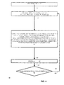
- FIG. 1 is a simplified flow chart diagram illustrating method 20 of the present invention.
- method 20 comprises steps 21, 23 and 25, illustrated by blocks.
- Solid lines 22 and 24, coupling the steps indicate a preferred method flow.
- Method 20 requires that the entire trellis is stored. It is very fast and it does not involve any learning period.
- Method 20 starts with step 21 of providing a trellis representative of an output of a SISO encoder, the trellis having a block length T.
- Step 21 is followed by step 23 of assigning an initial conditions to each starting node of the trellis for a forward iteration through the trellis and assigning an initial condition to each ending node of the trellis for a backward iteration through the trellis.
- Step 23 is followed by step 25 of computing a forward metric for each node, starting from the start of the trellis and advancing forward through the trellis and in parallel computing a backward metric for each node, starting from the end of the trellis and advancing backwards through the trellis.
- alphas (betas) of nodes of a stage are computed and the betas (alphas) of the nodes of an adjacent stage were previously computed
- the computation of alphas (betas) is integrated with the computation of lambda from the stage to the adjacent stage.
- gammas are calculated during step 25.
- method 20 is used to implement the Max Log MAP algorithm or the Log MAP algorithm.
- Max Log MAP algorithm or the Log MAP algorithm.
- Log MAP algorithms are referred to as Log MAP algorithms.
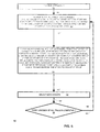
- FIG. 2 is a simplified flow chart diagram illustrating method 30 of the present invention.
- method 30 comprises steps 31, 33, 35 and 37, illustrated by blocks.
- Solid lines 32, 34 and 36, coupling the steps indicate a preferred method flow.
- Method 30 requires that the entire trellis is stored. It is very fast and it does not involve any learning period.
- Method 30 starts at step 31 of providing a trellis representative of an output of a SISO encoder, the trellis having a block length T.
- Step 31 is followed by step 33 of assigning an initial conditions to each starting node of the trellis for a forward iteration through the trellis and assigning an initial condition to each ending node of the trellis for a backward iteration through the trellis.
- Step 33 is followed by step 35 of computing a forward metric for each node, starting from the start of the trellis and advancing forward through a first half of the trellis and a backward metric for each node, starting from the end of the trellis and advancing backwards through a second half of the trellis.
- Step 35 is followed by step 37 of computing a backward metric for each node, and a lambda for each transition from a stage to an adjacent stage, starting from an end of the first half of the trellis and advancing backwards and computing a forward metric for each node and a lambda for each transition from a stage to an adjacent stage, starting from a start of the second half of the trellis and advancing forwards.
- gammas are calculated during step 35.
- method 30 is used to implement the Log MAP algorithms.
- FIG. 3-5 describe methods 40-60 for performing SISO decoding, whereas only a portion of a trellis is stored in memory.
- FIG. 3 is a simplified flow chart diagram illustrating method 40 of the present invention.
- method 40 comprises steps 41, 42, 43, 44, 45, 46 and 47, illustrated by blocks.
- Solid lines 41', 42', 43', 44', 45', 46' and 47', coupling the steps indicate a preferred method flow
- Method 20 requires that only a portion of the trellis is stored. It is very fast but it requires to undergo a learning period. Conveniently; the learning period L is much shorter than a window W in which valid alphas and betas are computed.
- Method 40 starts with step 41 of providing a trellis representative of an output of a convolutional encoder, the trellis having a block length T.
- Step 41 is followed by step 42 of assigning an initial condition to each node of a (j-L)'th stage of the trellis for a forward iteration through the trellis and assigning an initial condition to each node of a (i +L)'th stage of the trellis for a backward iteration through the trellis; wherein L is a length of a learning period, a forward window of length W starts at a j'th stage of the trellis and ends at a (j+W)'th stage of the trellis, a backward window of length W starts at a i'th stage of the trellis and ends at a (i-W)'th stage of the trellis.
- Step 42 is followed by step 43 of computing a forward metric for a each node, starting from the (j-L)'th stage of the trellis and ending at the (j+W)'th stage of the trellis and computing a backward metric of a plurality each node, starting from the (i +L)'th stage of the trellis and ending at the (i-W)'th stage of the trellis.
- Step 43 is followed by step 44 of assigning an initial condition to each node of a (j+L+W)'th stage of the trellis for a backward iteration through the trellis and assigning an initial condition to each node of a (i-W-L)'th stage of the trellis for a forward iteration through the trellis.
- Step 44 is followed by step 45 of computing a backward metric for each node. starting from the (j+L+W)'th stage of the trellis and ending at the (j+W+1)'th stage of the trellis and computing a forward metric of each node, starting from the (i-L-W)'th stage of the trellis and ending at the (i-1-W)'th stage of the trellis.
- Step 45 is followed by step 46 of computing a backward metric for each node and a lambda for each transition from a stage to an adjacent stage, starting from the (j+W)'th stage and ending at the j'th stage and computing a forward metric for each node and a lambda for each transition from a stage to an adjacent stage, starting from the (1-W)'th stage and ending at the i'th stage of the trellis.
- Step 46 is followed by step 47 of updating j and i.
- Step 47 is followed by query step 48 of checking if each lambda of the trellis is calculated. If the answer is yes, the process ends. Else, step 47 is followed by step 42.
- method 40 is used to implement the Log MAP algorithms.
- gammas are calculated during steps 43 and 44.
- FIG. 4 is a simplified flow chart diagram illustrating method 50 of the present invention.
- method 50 comprises steps 51-55, illustrated by blocks. Solid lines 51'-55' coupling the steps indicate a preferred method flow.
- Method 50 requires that only a portion of the trellis is stored. It is very fast but it requires to undergo a learning period. Conveniently, the learning period L are much shorter than a window W in which valid alphas and betas are computed.
- Method 50 starting at step 51 of providing a trellis representative of an output of a convolutional encoder, the trellis having a block length T;
- Step 51 is followed by step 52 of assigning an initial condition to each node of a (j-L)'th stage of the trellis for a forward iteration through the trellis and assigning an initial condition to each node of a (i +L)'th stage of the trellis for a backward iteration through the trellis;
- L is a length of a learning period
- a forward window of length W starts at a j'th stage of the trellis and ends at a (j+W)'th stage of the trellis
- a backward window of length W starts at a i'th stage of the trellis and ends at a (i-W)'th stage of the trellis;
- Step 52 is followed by step 53 of computing a forward metric for a each node, starting from the (j-L)'th stage of the trellis and ending at the (j+W)'th stage of the trellis and computing a backward metric of a plurality each node, starting from the (i +L)'th stage of the trellis and ending at the (i-W)'th stage of the trellis.
- alphas (betas) of nodes of a stage are computed and the betas (alphas) of the nodes of an adjacent stage were previously computed, the computation of alphas (betas) is integrated with the computation of lambda from the stage to the adjacent stage.
- Step 53 is followed by step 54 of updating j and i.
- Step 54 is followed by query step 55 of checking if each lambda of the trellis is calculated. If the answer is ves, the process ends. Else, step 54 is followed by step 52.
- method 50 is used to implement the Log MAP algorithms. Convemently, gammas are calculated during step 53.
- FIG. 5 is a simplified flow chart diagram illustrating method 60 of the present invention.
- method 60 comprises steps 61-65, illustrated by blocks. Solid lines 61'-65' coupling the steps indicate a preferred method flow.
- Method 60 requires that only a portion of the trellis is stored. It is very fast but it requires to undergo a learning period. Conveniently, the learning period L are much shorter than a window W in which valid alphas and betas are computed.
- Method 60 starting at step 61 of providing a trellis representative of an output of a convolutional encoder, the trellis having a block length T;
- Step 61 is followed by step 62 of assigning an initial condition for forward iteration through the trellis, to each node of a first group of stages, each stage located L stages before a starting stage of a forward window out of a group of forward windows, and assigning an initial condition for a backward iteration through the trellis, to each node of a second group of stages, each stage located L stages after an ending stage of a backward window out of a group of backward windows, wherein L is a length of a learning period, each forward window and each backward window is W stages long.
- Step 62 is followed by step 63 of computing a forward metric for a each node, starting from the first group of stages and ending at a third group of ending stages of the group of forward windows, and computing a backward metric for each node, starting from second group of stages and ending at a fourth group of ending stages of the group of the backward windows.
- alphas (betas) of nodes of a stage are computed and the betas (alphas) of the nodes of an adjacent stage were previously computed
- the computation of alphas (betas) is integrated with the computation of lambda from the stage to the adjacent stage
- Step 63 is followed by step 64 of selecting new groups.
- Step 64 is followed by query step 65 of selecting new groups and checking if each lambda of the trellis is calculated. If the answer is yes, the process ends. Else, step 65 is followed by step 62.
- the steps of calculating alphas and betas of methods 40-60 are executed after receiving enough signal samples to initiate a backward and forward recursion through the trellis.
- these steps are executed after receiving T/R signals, R being the coding rate of a convolutional encoder that its output signals are represented by the trellis.
- the steps of calculating alphas and betas of methods 20-30 are executed after receiving T/R signals.
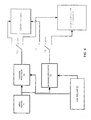
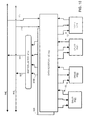
- FIG. 6 is a schematic description of system 70 for decoding a sequence of signals output by a convolutional encoder and transmitted over a channel according to a preferred embodiment of the invention.
- System 70 comprising input buffer 71, forward processor 73, backward processor 75, control unit 77, switching unit 79 memory module 81 and a double soft output processor 83.
- Input buffer 71 is adapted to receive the sequence of signals and provide them to forward processor 73 and backward processor 75.
- Forward processor 73 is adapted to receive the sequence of signals from input buffer and compute forward metrics (alphas).
- Backward processor 75 is adapted to receive the sequence of signals from input buffer 71 and compute backward metrics (betas).
- switching unit 79 comprises of two switches - forward switch 793 and backward switch 795.
- forward switch 793 can couple the output of forward processor 73 to memory module 81 (state “1"), to double soft output processor 83 (state “3") or can isolate the output of forward processor 73 (state “2").
- backward switch 795 can couple the output of backward processor 75 to memory module 81 (state “1"), 10 double soft output processor 83 (state “3") or can isolate the output of backward processor 75 (state “2").
- control unit 77 sends control signals to switching unit 79 so that the outputs backward processor 75 and forward processor 73 are isolated - they arc not coupled to memory module 81 and double soft output processor 83. Both switches are at state "2".
- forward processor 73 computes alphas of nodes of a stage and the betas of the adjacent stage haven't been previously computed the alphas are sent to memory module 81.
- forward switch 793 is at state "1" and the output of forward processor 73 is coupled to memory module 81.
- backward processor 75 computes betas of nodes of a stage and the alphas of the adjacent stage haven't been previously computed the betas are sent to memory module 81.
- backward switch 795 is at state "1" and the output of backward processor.73 is coupled to memory module 81.
- forward processor 73 computes alphas of nodes of a stage and the betas of the adjacent stage have been previously computed, the alphas are sent to double soft output processor 83.
- Double soft output processor 83 reads the betas of these nodes from memory module and computes lambda.
- Forward switch 793 is at state "3" and the output of forward processor 73 is coupled to dual soft output processor 83.
- Double soft output processor 83 reads the alphas of these nodes from memory module 81 and computes lambda.
- Backward switch 795 is at state "3" and the output of backward processor 75 is coupled to dual soft output processor 83.
- Double soft output processor 83 is adapted to calculate two lambdas in parallel.
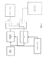
- FIG. 7 is a schematic description of system 80 for decoding a sequence of signals output by a convolutional encoder and transmitted over a channel according to a preferred embodiment of the invention.
- System 80 comprising input buffer 71, forward processor 73, backward processor 75, control unit 78, switching unit 80 memory module 81 and a soft output processor 84.
- Input buffer 71, forward processor 73, backward processor 75 and memory module 81 of FIG. 7 are analogues of input buffer 71.
- forward processor 73 backward processor 75.
- soft output processor 84 and dual soft output processor 83.
- switching unit 80 comprises of two switches ⁇ memory switch 803 and soft switch 801.
- memory switch 803 can couple memory module 81 to forward processor 73 (state “1"), to backward processor 75 (state “2”) or can isolate the input of memory module 81 (state “3”).
- soft switch 801 can couple the soft output processor 84 to backward processor 75 (state “1"), to forward processor 73 (state “3”) or can isolate the input of soft output decoder 84 (state “2").
- control unit 78 sends control signals to switching unit 80 so that the outputs backward processor 75 and forward processor 73 are not coupled to memory module 81 and double soft output processor 83.
- Soft switch 801 is at state "2" and memory switch 801 is at state switches are at state "3".
- forward processor 73 computes alphas of nodes of a stage and the betas of the adjacent stage haven't been previously computed the alphas are sent to memory module 81.
- memory switch is at state "1" and the output of forward processor 73 is coupled to memory module 81.
- backward processor 75 computes betas of nodes of a stage and the alphas of the adjacent stage haven't been previously computed the betas are sent to memory module 81.
- memory switch 803 is at state "2" and the output of backward processor 73 is coupled to memory module 81.
- forward processor 73 computes alphas of nodes of a stage and the betas of the adjacent stage have been previously computed, the alphas are sent to soft output processor 84.
- Soft output processor 84 reads the betas of these nodes from memory module and computes lambda. Conveniently, soft switch is at state "3" and the output of forward processor 73 is coupled to soft output processor 84.
- backward processor 75 computes betas of nodes of a stage and the alphas of the adjacent stage have been previously computed the betas are sent to soft output processor 84.
- Soft output processor 84 reads the alphas of these nodes from memory module 81 and computes lambda. Conveniently, soft switch is at state "1" and the output of backward processor 75 is coupled to soft output processor 84.
- Soft output processor 84 calculates lambdas when an alpha and a beta of a node are provided to it, either from memory module 81 or from one of forward and backward processors 73 and 75.
- Methods 20-60 can also be performed by other devices, such as but not limited to. multi-flow processors and Very Long Instruction Word processors.
- System 70 of FIG. 6 and system 80 of FIG. 7 are especially effective when L ⁇ W, thus most of their time the various processors provide valid results. Research and simulations have shown that W is about 4-10 times bigger than L.
- System 70 and system 80 are adapted to perform either one of methods 20-60. Conveniently, memory module 81 can be reduced if either one of these systems is configured to perform methods 40-60.
- the processing system 910 includes a processor core 912, a system interface unit (SIU) 914, a direct memory access unit 916, a peripheral 918, such as a serial communication port or timer, internal memory modules 920, 922, and an external memory interface module 919.
- the processing system 910 may also be referred to as a data processor.
- Processor core 912 includes address register file 926, program sequencer 924, data register files 928, 929 (the latter register file is shown in FIG. 10), address arithmetic logic units 930 (also referred to as address generation units (AGU)), multiply and accumulate (MAC) units (932) (also referred to generally as data arithmetic logic units (DALU)), AND bit field and logic unit 934.
- the address ALUs 930 are coupled to the address register file 926 via internal bus 960.
- the multiply and accumulate units 932 are coupled to the data register files 928, 929 via internal bus 962, and bit field unit 934 is coupled to the data register files 928, 929 via internal bus 964.
- the program sequencer 924 is coupled via the instruction bus 944 to the address ALUs 930, the DALUs 932, the bit field unit 934, and the instruction expansion accelerator 936.
- Processing system 910 has a scalable architecture that allows it to increment the number of MAC units and AGU units accordingly.
- FIGS. 8-12 show only a dual MAC unit configuration of processing system 910. The addition of MAC units allows to perform more operations in parallel, and reduced the speed of performing the MAP algorithm.
- the system 910 further includes program bus 938, first data bus 940, second data bus 942, peripheral bus 988, direct memory access (DMA) bus 984, and external memory interface bus 9102.
- Program bus 938 is coupled to program sequencer 924 via bus 946, to SIU 914 via bus 966, and to internal memory 920, 922 via buses 972 and 982 respectively.
- Data buses 940, 942 are coupled to address register file 926 via buses 948, 950 to data register files 928, 929 via buses 952, 954 and to instruction expansion accelerator 936 via buses 956, 958.
- Data buses 940, 942 are coupled to memory 920, 922 via buses 974-980.
- DMA bus 984 is coupled to SIU 914 via bus 990, to DMA 916 via bus 992, to peripheral unit 918 via bus 994, and to memory units 920, 922 via buses 995 and 997 respectively.
- Peripheral bus 988 is coupled to the SIU 914 via bus 996, to DMA 916 via bus 998, and to peripheral unit 918 via bus 9100.
- External memory bus 9102 is coupled to external memory interface module 919 and is coupled to external memory (not shown) in communication with the system 910.
- the program bus 938 is 9128 bits wide, and the other buses 940, 942, 984, and 988 are 964 bits wide. For convenience of explanation, the buses which are used to exchange addresses were not shown.
- the address register file 926 includes registers R0-R7, stack pointer (SP), N0-N3, M0-M2, MCTL, SAO-SA3, LCO-LC3.
- the program sequencer 924 includes the program counter, status register, and operating mode and status registers.
- the data register file 928 includes registers D0-D7 and the data register file 929 includes registers D8-D15.
- only a single register file may be used to save cost, such as with the one or two MAC configurations. In other high performance applications, more than two register files may also be used.
- FIG. 10 is a schematic diagram of the data register files, four ALU units and shifter/limiter. It is to he understood that the present invention is not to be limited by the above exemplary configurations and is not limited to the particular number of MAC units 32 or the particular arrangements thereof. Shifter/limiter 9110 is used to perform a Viterbi shift left operation on the survivor trellis value, and to insert a predetermined bit to the least significant bit of the survivor trellis value.
- the MAC unit 932 includes a multiplier 9110 and an adder 9112.
- the multiplier 9110 receives data input from the data register files 928, 929, and multiplies the data elements 9111, 9114 to produce a multiplied output 9116 that is input to the adder 9112.
- the adder sums a second data input 9120 and the multipher result 9116 to produce an accumulated result 9122 that is output back to the data register file 28, 29.
- each instruction fetch set comprises of fixed number of instructions.
- An instruction execution set is usually a subset of an instruction fetch set, usually a single instruction fetch set is comprised of a single instruction execution set, but can also have instructions from other instruction execution sets.
- An instruction execution set comprises of a plurality of instructions which can be executed in parallel by the various execution units within system 910.
- the embodiment illustrates a dispatch unit 220, eight instruction registers 2401-2409, collectively denoted 9240, for storing eight instructions every clock cycle, a program memory (either program memory 920 or 922), various data arithmetic logic units (DALUs) 9321-9324 (collectively denoted 932 in FIG. 1), address generation units (AGUs) 9301-9302, 9324 (collectively denoted 930 in FIG. 1), and control unit 940.
- the dispatch unit 9220 and instructions registers 9240 may form the program sequencer 924.
- dispatch unit 9220 groups the instructions into execution sets, and then simultaneously dispatched them via a routing mechanism to the appropriate execution units 9301-9302, 9321-9324, for parallel decoding and execution. Simultaneous dispatch means that execution of each of the grouped instructions is initiated during a common clock cycle. In the illustrated embodiment of the system 910, execution of each of the grouped instructions is initiated during a common clock cycle, but one or more of the grouped instructions may complete execution during a different clock cycle.
- System 910 uses a pipeline execution method that includes the execution stages of program pre-fetch, program fetch, dispatch and decode, address generation, and execute.
- System 910 ability to perform several operations in parallel, allows it to perform TC in a parallel manner.
- System 910 in a four MAC configuration and two dual MAC configured systems 910 are adapted to perform either one of methods 20-60.
- System 910 in a dual MAC configuration performs portions of steps 25. 35. 46. 53 and 63 in a serial manner.
- ⁇ 0, ⁇ 1, ⁇ 2 and ⁇ 3 are the forward metrics of n00, n01, n02 and n03.
- ⁇ 0, ⁇ 1, ⁇ 2 and ⁇ 3 are the backward metrics of nT0, nT1, nT3 and nT4
- ⁇ 00 is the branch metric associated with the transition from n00 to n12, from n01 to n10
- - ⁇ 00 is the branch metric associated with the transition from n00 to n10, from n01 to n12
- ⁇ 01 is the branch metric associated with the transition from n02 to n11, from n03 to n13
- - ⁇ 01 is the branch metric associated with the transition from n02 to n11, from n03 to n11
- ⁇ T0 is the branch metric associated with the transition from nT0 to nS2, from nT1 to nS0
- - ⁇ T0 is the branch metric associated with the transition from n
- D2.h stores ⁇ 1+ ⁇ 1, D2.1 stores ⁇ 0- ⁇ T0, D3.h stores ⁇ 3+ ⁇ T1, D3.1 stores ⁇ 2- ⁇ T0, D7.h stores ⁇ 1- ⁇ T1, D7.1 stores ⁇ 0- ⁇ T0, D6.h stores ⁇ 3- ⁇ T1, D6.1 stores ⁇ 2+ ⁇ T0.
- D0.h stores ⁇ 2+ ⁇ 01
- D0.1 stores ⁇ 0- ⁇ 00
- D1.h stores ⁇ 3+ ⁇ 01
- D1.1 stores ⁇ 1- ⁇ 00
- D4.h stores ⁇ 3- ⁇ 01
- D4.1 stores ⁇ 1+ ⁇ 00
- D5.h stores ⁇ 2- ⁇ 01
- D5.1 stores ⁇ 0+ ⁇ 00.
Landscapes
- Physics & Mathematics (AREA)
- Probability & Statistics with Applications (AREA)
- Engineering & Computer Science (AREA)
- Theoretical Computer Science (AREA)
- Error Detection And Correction (AREA)
Priority Applications (2)
| Application Number | Priority Date | Filing Date | Title |
|---|---|---|---|
| EP00100349A EP1115209A1 (fr) | 2000-01-07 | 2000-01-07 | Dispositif et procédé de décodage SISO en parallèle |
| US09/755,656 US20010054170A1 (en) | 2000-01-07 | 2001-01-05 | Apparatus and method for performing parallel SISO decoding |
Applications Claiming Priority (1)
| Application Number | Priority Date | Filing Date | Title |
|---|---|---|---|
| EP00100349A EP1115209A1 (fr) | 2000-01-07 | 2000-01-07 | Dispositif et procédé de décodage SISO en parallèle |
Publications (1)
| Publication Number | Publication Date |
|---|---|
| EP1115209A1 true EP1115209A1 (fr) | 2001-07-11 |
Family
ID=8167584
Family Applications (1)
| Application Number | Title | Priority Date | Filing Date |
|---|---|---|---|
| EP00100349A Withdrawn EP1115209A1 (fr) | 2000-01-07 | 2000-01-07 | Dispositif et procédé de décodage SISO en parallèle |
Country Status (2)
| Country | Link |
|---|---|
| US (1) | US20010054170A1 (fr) |
| EP (1) | EP1115209A1 (fr) |
Cited By (4)
| Publication number | Priority date | Publication date | Assignee | Title |
|---|---|---|---|---|
| GB2365290A (en) * | 2000-02-10 | 2002-02-13 | Motorola Inc | Soft output decoder for convolutional codes using a sliding window technique which involves a learning period, stored forward recursion and backward recursion |
| GB2365291A (en) * | 2000-02-10 | 2002-02-13 | Motorola Inc | Soft output decoder for convolutional codes using a sliding window technique which involves a learning period, stored backward recursion and forward recursion |
| WO2002021701A1 (fr) * | 2000-09-06 | 2002-03-14 | Motorola Inc., A Corporation Of The State Of Delaware | Decodeur a sorties ponderees pour codes a convolution |
| WO2004038928A1 (fr) * | 2002-10-23 | 2004-05-06 | Modem-Art Limited | Unite de communication et procede de decodage |
Families Citing this family (7)
| Publication number | Priority date | Publication date | Assignee | Title |
|---|---|---|---|---|
| SG97926A1 (en) * | 2000-08-29 | 2003-08-20 | Oki Techno Ct Singapore Pte | Soft-in soft-out decoder used for an iterative error correction decoder |
| US7200799B2 (en) * | 2001-04-30 | 2007-04-03 | Regents Of The University Of Minnesota | Area efficient parallel turbo decoding |
| CN1682449A (zh) * | 2002-09-18 | 2005-10-12 | 皇家飞利浦电子股份有限公司 | 使用数据窗口来解码数据的方法 |
| US7246295B2 (en) * | 2003-04-14 | 2007-07-17 | Agere Systems Inc. | Turbo decoder employing simplified log-map decoding |
| US7447970B2 (en) * | 2004-06-16 | 2008-11-04 | Seagate Technology, Inc. | Soft-decision decoding using selective bit flipping |
| US9319250B2 (en) | 2013-03-15 | 2016-04-19 | Jonathan Kanter | Turbo decoding techniques |
| US9608851B2 (en) | 2013-03-15 | 2017-03-28 | Jonathan Kanter | Turbo decoding techniques |
Citations (1)
| Publication number | Priority date | Publication date | Assignee | Title |
|---|---|---|---|---|
| US5933462A (en) * | 1996-11-06 | 1999-08-03 | Qualcomm Incorporated | Soft decision output decoder for decoding convolutionally encoded codewords |
-
2000
- 2000-01-07 EP EP00100349A patent/EP1115209A1/fr not_active Withdrawn
-
2001
- 2001-01-05 US US09/755,656 patent/US20010054170A1/en not_active Abandoned
Patent Citations (1)
| Publication number | Priority date | Publication date | Assignee | Title |
|---|---|---|---|---|
| US5933462A (en) * | 1996-11-06 | 1999-08-03 | Qualcomm Incorporated | Soft decision output decoder for decoding convolutionally encoded codewords |
Non-Patent Citations (4)
| Title |
|---|
| DAWID H., GEHNEN G., MEYR H.: "MAP CHANNEL DECODING: ALGORITHM AND VLSI ARCHITECTURE", PROCEEDINGS OF IEEE WORKSHOP ON VLSI SIGNAL PROCESSING, 20 October 1993 (1993-10-20) - 22 October 1993 (1993-10-22), VELDOVEN (NL), pages 141 - 149, XP002113702 * |
| DAWID H., MEYR H.: "Real-Time algorithms and VLSI architectures for soft output MAP convolutional decoding", PROCEEDINGS ON THE SIXTH IEEE INTERNATIONAL SYMPOSIUM ON PERSONAL, INDOOR AND MOBILE RADIO COMMUNICATIONS (PIMRC'95), vol. 1, 22 September 1995 (1995-09-22) - 29 September 2025 (2025-09-29), TORONTO (CA), pages 193 - 197, XP002176458 * |
| LIU Y, FOSSORIER M., LIN S.: "MAP algorithms for decoding linear block codes based on sectionalized trellis diagrams", IEEE GLOBECOM 1998, vol. 1, 8 November 1998 (1998-11-08) - 12 November 1998 (1998-11-12), pages 562 - 566, XP002142015 * |
| YIIN L ET AL: "MLSE AND SOFT-OUTPUT EQUALIZATION FOR TRELLIS-CODED CONTINUOUS PHASE MODULATION", IEEE TRANSACTIONS ON COMMUNICATIONS,US,IEEE INC. NEW YORK, vol. 45, no. 6, 1 June 1997 (1997-06-01), pages 651 - 659, XP000659559, ISSN: 0090-6778 * |
Cited By (9)
| Publication number | Priority date | Publication date | Assignee | Title |
|---|---|---|---|---|
| GB2365290A (en) * | 2000-02-10 | 2002-02-13 | Motorola Inc | Soft output decoder for convolutional codes using a sliding window technique which involves a learning period, stored forward recursion and backward recursion |
| GB2365291A (en) * | 2000-02-10 | 2002-02-13 | Motorola Inc | Soft output decoder for convolutional codes using a sliding window technique which involves a learning period, stored backward recursion and forward recursion |
| GB2365290B (en) * | 2000-02-10 | 2002-11-20 | Motorola Inc | Soft output decoder for convolutional codes |
| GB2365291B (en) * | 2000-02-10 | 2002-11-20 | Motorola Inc | Soft output decoder for convolutional codes |
| US6868132B1 (en) | 2000-02-10 | 2005-03-15 | Motorola, Inc. | Soft output decoder for convolutional codes |
| US6901117B1 (en) | 2000-02-10 | 2005-05-31 | Motorola, Inc. | Soft output decoder for convolutional codes |
| WO2002021701A1 (fr) * | 2000-09-06 | 2002-03-14 | Motorola Inc., A Corporation Of The State Of Delaware | Decodeur a sorties ponderees pour codes a convolution |
| US6452979B1 (en) | 2000-09-06 | 2002-09-17 | Motorola, Inc. | Soft output decoder for convolutional codes |
| WO2004038928A1 (fr) * | 2002-10-23 | 2004-05-06 | Modem-Art Limited | Unite de communication et procede de decodage |
Also Published As
| Publication number | Publication date |
|---|---|
| US20010054170A1 (en) | 2001-12-20 |
Similar Documents
| Publication | Publication Date | Title |
|---|---|---|
| US7895497B2 (en) | Apparatus and method using reduced memory for channel decoding in a software-defined radio system | |
| US6192501B1 (en) | High data rate maximum a posteriori decoder for segmented trellis code words | |
| EP1127411B1 (fr) | Normalisation metrique d'etat efficace par code en treillis | |
| US7107509B2 (en) | Higher radix Log MAP processor | |
| EP1130789A2 (fr) | Décodage d'un code convolutif avec décisions douces | |
| WO2011082509A1 (fr) | Procédé et dispositif de décodage de turbo code | |
| US7984368B2 (en) | Method and system for increasing decoder throughput | |
| US8196006B2 (en) | Modified branch metric calculator to reduce interleaver memory and improve performance in a fixed-point turbo decoder | |
| US7234100B1 (en) | Decoder for trellis-based channel encoding | |
| JP2003318746A (ja) | 軟出力復号器 | |
| US6477679B1 (en) | Methods for decoding data in digital communication systems | |
| US20010054170A1 (en) | Apparatus and method for performing parallel SISO decoding | |
| JP2004343716A (ja) | 畳み込み符号化信号の伝送形式をブラインド検出する方法および復号器 | |
| EP1564893A1 (fr) | Dispositif de décodage Turbo, méthode de décodage Turbo et programme informatique | |
| US7200798B2 (en) | Unified serial/parallel concatenated convolutional code decoder architecture and method | |
| EP1128560B1 (fr) | Dispositif et méthode de décodage SISO | |
| JP2006041960A (ja) | ターボ復号装置及びターボ復号方法並びにプログラム | |
| KR100336246B1 (ko) | 디지탈프로세서및코-프로세서를구비한집적회로 | |
| US6477681B1 (en) | Methods for decoding data in digital communication systems | |
| US8032811B2 (en) | Efficient almost regular permutation (ARP) interleaver and method | |
| JP3888135B2 (ja) | 誤り訂正符号復号装置 | |
| JP5075642B2 (ja) | トレリス線図のバタフライ構造を用いたmap復号化のためのメトリック計算 | |
| EP1543624A2 (fr) | Procede de decodage de donnees au moyen de fenetres de donnees | |
| US7120851B2 (en) | Recursive decoder for switching between normalized and non-normalized probability estimates | |
| JP2614524B2 (ja) | 誤り訂正符号の復号方法 |
Legal Events
| Date | Code | Title | Description |
|---|---|---|---|
| PUAI | Public reference made under article 153(3) epc to a published international application that has entered the european phase |
Free format text: ORIGINAL CODE: 0009012 |
|
| AK | Designated contracting states |
Kind code of ref document: A1 Designated state(s): DE FR GB |
|
| AX | Request for extension of the european patent |
Free format text: AL;LT;LV;MK;RO;SI |
|
| 17P | Request for examination filed |
Effective date: 20020111 |
|
| AKX | Designation fees paid |
Free format text: DE FR GB |
|
| 17Q | First examination report despatched |
Effective date: 20020326 |
|
| STAA | Information on the status of an ep patent application or granted ep patent |
Free format text: STATUS: THE APPLICATION IS DEEMED TO BE WITHDRAWN |
|
| 18D | Application deemed to be withdrawn |
Effective date: 20030716 |