EP1115466B1 - Vorrichtung und verfahren zur abdichtung einer vielzahl von chromatographischen säulen - Google Patents
Vorrichtung und verfahren zur abdichtung einer vielzahl von chromatographischen säulen Download PDFInfo
- Publication number
- EP1115466B1 EP1115466B1 EP99934056A EP99934056A EP1115466B1 EP 1115466 B1 EP1115466 B1 EP 1115466B1 EP 99934056 A EP99934056 A EP 99934056A EP 99934056 A EP99934056 A EP 99934056A EP 1115466 B1 EP1115466 B1 EP 1115466B1
- Authority
- EP
- European Patent Office
- Prior art keywords
- sealing
- heads
- sealing heads
- springs
- columns
- Prior art date
- Legal status (The legal status is an assumption and is not a legal conclusion. Google has not performed a legal analysis and makes no representation as to the accuracy of the status listed.)
- Expired - Lifetime
Links
- 238000007789 sealing Methods 0.000 title claims abstract description 272
- 238000000034 method Methods 0.000 title claims abstract description 14
- 238000004587 chromatography analysis Methods 0.000 title claims description 72
- 230000006835 compression Effects 0.000 claims abstract description 40
- 238000007906 compression Methods 0.000 claims abstract description 40
- 230000005540 biological transmission Effects 0.000 claims description 28
- 230000033001 locomotion Effects 0.000 claims description 12
- 239000012530 fluid Substances 0.000 claims description 10
- 238000003780 insertion Methods 0.000 claims description 5
- 230000037431 insertion Effects 0.000 claims description 5
- 230000000717 retained effect Effects 0.000 claims description 3
- 230000004044 response Effects 0.000 claims description 2
- 238000004891 communication Methods 0.000 claims 3
- 230000013011 mating Effects 0.000 claims 3
- 230000000712 assembly Effects 0.000 abstract description 6
- 238000000429 assembly Methods 0.000 abstract description 6
- 238000004811 liquid chromatography Methods 0.000 abstract description 4
- 239000007788 liquid Substances 0.000 description 5
- 230000007246 mechanism Effects 0.000 description 5
- 238000004458 analytical method Methods 0.000 description 3
- 230000004913 activation Effects 0.000 description 2
- 239000012501 chromatography medium Substances 0.000 description 2
- 150000001875 compounds Chemical class 0.000 description 2
- 230000000694 effects Effects 0.000 description 2
- 230000036316 preload Effects 0.000 description 2
- 238000000926 separation method Methods 0.000 description 2
- 230000005526 G1 to G0 transition Effects 0.000 description 1
- 230000003213 activating effect Effects 0.000 description 1
- 238000013459 approach Methods 0.000 description 1
- 230000008859 change Effects 0.000 description 1
- 238000013461 design Methods 0.000 description 1
- 239000000463 material Substances 0.000 description 1
- 230000005012 migration Effects 0.000 description 1
- 238000013508 migration Methods 0.000 description 1
- 238000012856 packing Methods 0.000 description 1
- 239000002904 solvent Substances 0.000 description 1
Images





Classifications
-
- G—PHYSICS
- G01—MEASURING; TESTING
- G01N—INVESTIGATING OR ANALYSING MATERIALS BY DETERMINING THEIR CHEMICAL OR PHYSICAL PROPERTIES
- G01N30/00—Investigating or analysing materials by separation into components using adsorption, absorption or similar phenomena or using ion-exchange, e.g. chromatography or field flow fractionation
- G01N30/02—Column chromatography
- G01N30/60—Construction of the column
- G01N30/6004—Construction of the column end pieces
- G01N30/6026—Fluid seals
-
- G—PHYSICS
- G01—MEASURING; TESTING
- G01N—INVESTIGATING OR ANALYSING MATERIALS BY DETERMINING THEIR CHEMICAL OR PHYSICAL PROPERTIES
- G01N30/00—Investigating or analysing materials by separation into components using adsorption, absorption or similar phenomena or using ion-exchange, e.g. chromatography or field flow fractionation
- G01N30/02—Column chromatography
- G01N30/60—Construction of the column
- G01N30/6034—Construction of the column joining multiple columns
- G01N30/6043—Construction of the column joining multiple columns in parallel
-
- G—PHYSICS
- G01—MEASURING; TESTING
- G01N—INVESTIGATING OR ANALYSING MATERIALS BY DETERMINING THEIR CHEMICAL OR PHYSICAL PROPERTIES
- G01N30/00—Investigating or analysing materials by separation into components using adsorption, absorption or similar phenomena or using ion-exchange, e.g. chromatography or field flow fractionation
- G01N30/02—Column chromatography
- G01N2030/022—Column chromatography characterised by the kind of separation mechanism
- G01N2030/027—Liquid chromatography
-
- G—PHYSICS
- G01—MEASURING; TESTING
- G01N—INVESTIGATING OR ANALYSING MATERIALS BY DETERMINING THEIR CHEMICAL OR PHYSICAL PROPERTIES
- G01N30/00—Investigating or analysing materials by separation into components using adsorption, absorption or similar phenomena or using ion-exchange, e.g. chromatography or field flow fractionation
- G01N30/02—Column chromatography
- G01N30/50—Conditioning of the sorbent material or stationary liquid
- G01N30/52—Physical parameters
- G01N2030/522—Physical parameters pressure
-
- G—PHYSICS
- G01—MEASURING; TESTING
- G01N—INVESTIGATING OR ANALYSING MATERIALS BY DETERMINING THEIR CHEMICAL OR PHYSICAL PROPERTIES
- G01N30/00—Investigating or analysing materials by separation into components using adsorption, absorption or similar phenomena or using ion-exchange, e.g. chromatography or field flow fractionation
- G01N30/02—Column chromatography
- G01N30/26—Conditioning of the fluid carrier; Flow patterns
- G01N30/38—Flow patterns
- G01N30/46—Flow patterns using more than one column
- G01N30/466—Flow patterns using more than one column with separation columns in parallel
-
- G—PHYSICS
- G01—MEASURING; TESTING
- G01N—INVESTIGATING OR ANALYSING MATERIALS BY DETERMINING THEIR CHEMICAL OR PHYSICAL PROPERTIES
- G01N30/00—Investigating or analysing materials by separation into components using adsorption, absorption or similar phenomena or using ion-exchange, e.g. chromatography or field flow fractionation
- G01N30/02—Column chromatography
- G01N30/60—Construction of the column
- G01N30/6047—Construction of the column with supporting means; Holders
Definitions
- the invention relates to sealing a plurality of columns for performing liquid chromatography analyses.
- Liquid chromatography is a technique for separating the individual compounds that exist in a subject sample.
- the subject sample is carried in a liquid, called a mobile phase.
- the mobile phase carrying the subject sample is caused to migrate through a media, called a stationary phase.
- Different compounds will have differing rates of migration through the media, which effects the separation of the components in the subject sample.
- Liquid chromatography is commonly performed with reusable or disposable columns, both of which are usually cylindrical, in which the media bed is bounded axially by porous plates, or by plates containing defined flowpaths, chrough which the mobile phase will flow. (See U.S. Pat. No. 5,601,708 to Leavesley, and U.S. Pat. No.
- Patent application GB-A-1 065 797 discloses an apparatus for sealing a respective chromatography column out of a plurality of chromatography columns by means of a sealing head upon compression of that sealing heads. Springs, retainers and transmission plates are used to compress the head.
- US patent US-A-4 597 866 discloses a chromatography apparatus with a column and a head fitting in the column where a piston is used to compress a filling in the column.
- the invention in general relates to sealing flowpath connections for a plurality of chromatography columns.
- the apparatus involves an upper sealing assembly and a lower sealing assembly.
- the upper sealing assembly includes a plurality of upper sealing heads and the lower sealing assembly includes a plurality of lower sealing heads.
- Each sealing head defines a flowpath for the passage of liquids.
- Both the upper and the lower sealing heads are sized to receive the open ends of the chromatography columns.
- Each of the upper sealing heads is aligned with one of the lower sealing heads.
- chromatography columns are fitted between one of the lower sealing heads and the corresponding upper sealing head.
- Compressive forces are applied to each corresponding pair of the upper and the lower sealing heads that retain a chromatography column.
- the compressive forces may be applied by pressing the sealing heads against media beds in the columns and thus causing the sealing heads to create seals with the chromatography columns.
- the compressive forces are reduced so as to release the seals created between the sealing heads and the chromatography columns and to facilitate the separation of the columns from the upper and lower sealing assemblies. Any tubing connected to the sealing assemblies may remain in place when the sealing heads are removed from the columns.
- the apparatus also involves a pressure containment vessel that surrounds the chromatography columns. Radial compressive force on the chromatography columns may be increased by introducing a pressurized fluid into a radial compression inlet in the pressure containment vessel.
- the upper sealing assembly also includes an upper plate through which the upper sealing heads are fitted.
- the lower sealing assembly also includes a lower plate through which the lower sealing heads are slidably fitted. The upper plate and the lower plate are sized to close the pressure containment vessel. Clamps are used to secure the upper plate to the pressure containment vessel.
- the upper sealing assembly may slide on rails into alignment with the lower sealing assembly.
- the compressive force required to seal the columns may be supplied by any desired mechanism that can supply a compressive force to the sealing heads.
- a mechanism with an hydraulic piston may be used to supply the compressive force.
- the piston may transmit compressive force through a pivot arm or other linkage.
- a compressive force is supplied to the sealing heads through springs.
- the springs may be subjected to a preload force. Alternately, the springs may be disposed so as to supply the necessary compressive force themselves.
- the piston may be used to provide additional compressive force to the springs, in order to reduce the compression on the lower sealing heads, the media beds, and the upper sealing heads, so that the columns may be inserted into or removed from the apparatus.
- sealing heads that can be inserted into columns with low insertion force; however, embodiments of the invention may employ any type of sealing head.
- the columns may be sealed by forcing a one-piece sealing head with an elastomeric o-ring (connected radially or to an end of the sealing head) into the columns.
- tapered sealing heads can be forced into a column without employing an o-ring to create a seal.
- Other types of sealing heads employ o-rings or knife edges (see U.S. Pat. No. 5,601,708 to Leavesley) oriented axially on a sealing head that creates seals with the edges of an open end of a column.
- Embodiments of the invention may include one or more of the following advantages.
- the sealing assemblies can create secure seals in a plurality of chromatography columns simultaneously.
- Embodiments of the invention can limit the gap between the media bed and the sealing heads in a column that is positioned for chromatographic analysis.
- Seals can be created in a plurality of columns having media beds of differing lengths. Sealing heads may move independently of each other in order to create effective seals in a plurality of columns having media beds of differing lengths.
- Embodiments of the invention may be used with a variety of different types of sealing heads. A plurality of columns may be subjected to chromatography analyses at one time.
- Embodiments of the invention may be used with either disposable or reusable chromatography columns. Embodiments of the invention may be used with either flexible-walled or rigid-walled chromatography columns. A plurality of chromatography columns can be subjected to similar axial or radial compressive forces or to a combination of both axial and radial compressive forces. Axial and radial compressive forces applied to the chromatography columns compress the media beds, giving the media a more uniform consistency and making the columns more reliable for chromatographic analysis. The operation of closing and clamping the upper sealing assembly and the operation of sealing the columns are separated.
- the pressure containment vessel may be closed without having to apply enough force either to seal the chromatography columns or to provide axial or compressive forces to the media beds; thus, the design of the upper sealing assembly is simplified (as levers or linkages are not required to apply these forces) and the effort required by the operator is reduced and simplified, as well.
- Separate mechanisms may be employed to supply the forces needed to seal the chromatography columns and to supply radial compressive forces to the columns. Additional axial compressive force may be provided to the media bed beyond any force needed to seal the chromatography columns.
- the force required to activate the sealing heads or to provide axial compression may be supplied by springs, as opposed to an hydraulic or similar mechanism, so that loss of force from the hydraulic or similar mechanism will not impair the seals between the sealing heads and the columns.
- embodiments of the invention can simplify the performance of chromatography analyses with a large throughput volume of mobile phase and subject sample.
- embodiments of the invention can be used to purify or analyze several different samples using one type of media in a chromatography column, or a single sample with several different types of media, each in a different column.
- Embodiments of the invention also facilitate the division of a large sample into smaller samples, in order to increase the amount of material that may be purified in a given time with a single type of chromatography media and solvent system.
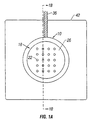
- FIGS. 1A-1D there is shown an apparatus employing pressure containment vessel 10 for enclosing and providing pressure to the external walls of a plurality of chromatography columns, such as chromatography column 12.
- Column 12 is cylindrical and contains media bed 14 that is bounded axially at the top and bottom by porous plates 16.
- Chromatography columns are sealed by upper sealing assembly 18 and lower sealing assembly 20, which have connections for sample inflow and outflow tubing.
- Upper sealing assembly 18 has a plurality of upper sealing heads 22, (see FIG 1C).
- Lower sealing assembly 20 has a plurality of lower sealing heads 24, (see FIG. 1D). Both upper and lower sealing heads define flowpaths for the passage of liquids. The structure and operation of the sealing heads are described below with reference to FIGS. 4A-4B.
- Upper sealing assembly 18 includes upper plate 26 and lower sealing assembly 20 includes lower plate 28.
- Upper plate 26 contains a plurality of openings through which upper sealing heads 22 are sealably fitted.
- Upper plate 26 is sealably connected to pressure containment vessel 10 with clamps 30.
- Lower plate 28 contains a plurality of openings through which lower sealing heads 24 are sealably fitted.
- Guides 32 and upper guides 34 retain chromatography columns in their proper positions.
- Guides 32 and upper guides 34 are tubular.
- Transverse support rod 36 may be connected to pressure containment vessel 10, to provide stability to the apparatus.
- Upper guides 34 are attached to upper plate 26.
- Guides 32 are attached to lower plate 28, and guide support 38 is connected to pressure containment vessel 10.
- Pressure containment vessel 10 is connected to skirt 40, which is, in turn, mounted on base 42.
- Upper sealing heads 22 and lower sealing heads 24 create seals with chromatography columns such as column 12, when sufficient compressive force is applied to the sealing heads. (The disposition of one of upper sealing heads 22 is shown in FIG. 1C.) Compressive force is applied to lower sealing heads 24, which are slidably and sealably connected to lower plate 28. Lower sealing heads 24 are capable of sliding axially, relative to lower plate 28, independently with respect to each other. Lower sealing heads 24 are thus pressed against porous plates 16 which bound the media 14 contained within chromatography columns such as column 12. Compressive force is thus transmitted through the chromatography columns to upper sealing heads 22.
- Compressive force acting on both lower sealing heads 24 and upper sealing heads 22 effects a seal at both ends of the chromatography columns between the sealing heads and the inner surfaces of the columns by radial expansion of elastomeric sealing rings as described below with reference to FIGS. 4A-4B.
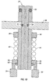
- compressive force is supplied to lower sealing heads 24 through springs 44 by piston 46 in reaction to the introduction of pressurized fluid into piston chamber 48 through piston activation inlet 50. Introducing pressurized fluid into piston chamber 48 causes piston 46 to rise. Piston 46 is slidably adjacent to the walls of piston chamber 48. Transmission members 52 are connected to piston 46. Transmission members 52 are in contact with transmission plate 54. Transmission plate 54 defines openings through which lower sealing heads 24 may pass, as transmission plate 54 rises in response to the motion of piston 46. Transmission plate 54 is in contact with spring compression members 56, which are slidably adjacent to and surround lower sealing heads 24. (FIG. 1D). Spring compression members 56 are also in contact with springs 44. Compressive force exerted on springs 44 by spring compression members 56 is transmitted to lower sealing heads 24 because the motion of springs 44 is impeded by upper retaining rings 58, which are fixedly connected to lower sealing heads 24.
- springs 46 are retained in a compressed state, when bounded by upper retaining rings 58 and by spring compression members 56.
- Spring compression members 56 are, in turn, bounded by lower retaining ring 60 as seen in FIG. 1D, thus providing a minimum preload force between spring compression members 56 and sealing heads 24.
- Lower retaining rings 60 are fixedly connected to lower sealing heads 24.
- Sealing elements 64 provide pressure seals between parts of the apparatus that contact each other, such as: between upper plate 26 and the pressure containment vessel 10; between lower plate 28 and pressure containment vessel 10; and between any of upper sealing heads 22 and upper plate 26; between any of lower sealing heads 24 and lower plate 28.
- Appropriate parts e.g., upper plate 26, lower plate 28, pressure containment vessel 10, upper sealing heads 22, or lower sealing heads 24
- chromatography columns such as column 12 are inserted into guides 32 and mated with lower sealing heads 24.
- Upper sealing assembly 18 is then placed on pressure containment vessel 10 so that each of upper guides 34 surrounds one of the columns and upper sealing heads 22 mate with the columns.
- Clamp 30 is attached to connect upper plate 26 to pressure containment vessel 10.
- Introducing a fluid into piston chamber 48 through inlet 50 increases the pressure in chamber 48 and creates an upward force on piston 46 which is transmitted through transmission members 52 to transmission plate 54 and spring compression members 56 to springs 44.
- Springs 44 transmit the compressive force to upper retaining rings 58 and lower sealing heads 24 through the porous plates and media of the columns, to upper sealing heads 22 and against upper plate 26.
- activating piston chamber 48 moves piston 46, transmission members 52, and spring compression members 56 upward to apply compressive force to lower sealing heads 24 and upper sealing heads 22.
- springs 144 are disposed so that they provide the compressive force required to activate both upper sealing heads 122 and lower sealing heads 124, unless springs 144 are deactivated by piston 146. In the embodiment shown in FIG. 2, this is achieved by situating springs 144 within recesses defined by lower plate 128. Compressive forces are communicated to lower sealing heads 124 when springs 144 are compressed between lower plate 128 and upper retainers 158. Upper retainers 158 are in fixed relation to lower sealing heads 124.
- Piston 146 is disposed within piston chamber 148 so that the introduction of a pressurized fluid through piston activation inlet 150 draws transmission member 152, transmission plate 154, and lower sealing heads 124 away from upper sealing heads 122, thus reducing axial compression in upper sealing heads 122, lower sealing heads 124, and media 114 in columns such as column 112.
- Transmission plate 154 may be fixed to lower sealing heads 124.
- transmission plate 154 is slidably adjacent to lower sealing heads 124, yet retained by retaining members 166, so that forces affecting transmission plate 154 are transmitted to lower sealing heads 124 and springs 144.
- loss or variation of fluid pressure in piston chamber 148 does not affect the quality of the seals between upper sealing heads 122 or lower sealing heads 124 and the columns.
- lower plate 128 defines drain passage 168 to permit the egress of any liquids that accumulate within recesses defined by lower plate 128.
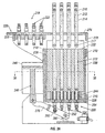
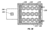
- containment structures 232 define tubular openings 272 that are sized to slidably receive chromatography columns 212 containing media 214 bounded by upper porous plates 216 and lower porous plates 217.
- Containment structures 232 are slidably mounted to vertical rails 238, so that containment structures 232 may slide vertically relative to the frame elements.
- Lateral frame elements 210 are fixed to vertical rails 238 opposed to containment structures 232.
- Lower sealing assembly 220 includes lower plate 228, a plurality of sealing heads 224 slidably mounted through lower plate 228, and springs 244 contained within lower plate 228.
- the disposition of one of lower sealing heads 224 is shown in detail in FIG. 3E.
- Lower sealing heads 224 have upper retaining projections 258 (FIG. 3E) set against springs 244. The retaining projections 258 can slide relative to lower plate 228.
- Lower sealing heads have a structure similar to that shown schematically in FIGS. 4A-4B.
- Upper sealing assembly 218 includes upper plate 234, upper frame element 226, and upper sealing heads 222.
- Upper frame element 226 is slidably mounted on horizontal rails 274 so that upper sealing assembly 218 can slide into or out of alignment with lower sealing assembly 220.
- Horizontal rails 274 are fixed to upper frame elements 278.
- Upper sealing heads 222 have a structure similar to that shown schematically in FIGS. 5A-5B.
- FIGS. 3A-3E also has piston 246 which is slidably adjacent to piston chamber 248.
- Piston 246 is pivotally connected to arm 276, which is in turn pivotally connected to transmission member 252.
- Arm 276 can pivot about axis 282.
- Transmission member 252 is slidably adjacent to guide 280 and is connected to transmission plate 254.
- Lower sealing heads 224 pass through and can slide relative to transmission plate 254.
- FIGS. 3A-3E In operation of the embodiment of FIGS. 3A-3E, while upper sealing assembly 218 is out of alignment with lower sealing assembly 220, chromatography columns 212 are placed into tubular openings 272 so that lower sealing heads 224 enter columns 212.
- FIG. 3A shows columns 212 positioned for entry into tubular openings 272.
- Upper sealing assembly 218 is slid into alignment with lower sealing assembly 220, as seen in FIG. 3C.
- piston 246 With the sealing assemblies 218, 220 aligned, piston 246 is activated so that it descends relative to piston chamber 248 and causes arm 276 to pivot about axis 282.
- the angular movement of arm 276 raises transmission member 252 relative to guide 280.
- the upward movement of transmission member 252 lifts transmission plate 254, lower plate 228, and containment structures 232, the last of which slides relative to vertical rails 238.
- sealing head Any type of sealing head may be used with the invention.
- sealing heads requiring only a low insertion force are employed.
- the low-insertion-force sealing heads may each create a single seal or a plurality of seals and the sealing heads may be used in conjunction with a sample module that fits into the column.
- one type of low-insertion-force sealing head 310 contains first head piece 312, second head piece 314 and elastomeric sealing member 316.
- First head piece 312 has body portion 318 that is slidably fitted into central opening 342 in second head piece 314.
- Body portion 318 defines flowpath 320, along axis 322, for liquids used in chromatography.
- First head piece 312 also has cylindrical outwardly extending shoulder 324 that is broader than the central opening in second head piece 314, and contact face 330.
- Elastomeric sealing member 316 has an annular shape and is disposed between first compression face 326 located on shoulder 324 of the first head piece and second compression face 328 on second head piece 314.
- FIG. 4B shows the connection of sealing head 310.
- sealing head 310 is inserted into an end of chromatography column 332 having media 334 that is bounded axially by porous plate 336.
- elastomeric sealing member 316 When elastomeric sealing member 316 is not compressed, sealing head 310 slides easily into column 332. After insertion, moving first head piece 312 upward relative to second head piece 314 compresses elastomeric sealing member 316 between first compression face 326 and second compression face 328, thus causing sealing member 316 to expand radially. The radial expansion of elastomeric sealing member 316 causes it to form a seal with column 332.
- the relative movement of the head pieces can be achieved by compressing second head piece 314 against porous plate 336 and media 334. Such a compressive force will compress elastomeric sealing member 316 against shoulder 324 and will, in turn, compress contact face 330 against porous plate 336.
- the first head piece of a low-insertion-force sealing head is slidable relative to the upper plate and the second head piece is fixedly connected to the upper plate.
- the second head piece is slidably connected to the lower plate.
- retaining rings and retaining projections can be used interchangeably as retainers.
Landscapes
- Physics & Mathematics (AREA)
- Health & Medical Sciences (AREA)
- Life Sciences & Earth Sciences (AREA)
- Chemical & Material Sciences (AREA)
- Analytical Chemistry (AREA)
- Biochemistry (AREA)
- General Health & Medical Sciences (AREA)
- General Physics & Mathematics (AREA)
- Immunology (AREA)
- Pathology (AREA)
- Treatment Of Liquids With Adsorbents In General (AREA)
Claims (39)
- Vorrichtung für das gleichzeitige Abdichten einer Vielzahl von zylindrischen chromatographischen Säulen (12; 212), wobei jede Säule ein Medium (14; 214) enthält und zwei Ende aufweist, wobei die Vorrichtung ein oberes Abdichtsystem (18; 218) und ein unteres Abdichtsystem (20; 220) enthält, dadurch gekennzeichnet, dass
das obere Abdichtsystem (18; 218) eine Vielzahl von oberen Abdichtköpfen (22; 122; 222) aufweist, wobei jeder der oberen Abdichtköpfe (22; 122; 222) eine zylindrische Abdichtfläche aufweist, die so dimensioniert ist, dass sie von einer zylindrischen Fläche an einem Ende einer der chromatographischen Säulen (12; 212) aufgenommen werden kann, wobei jeder der oberen Abdichtköpfe (22; 122; 222) ein Abdichtglied (63; 316) umfasst, das in der Lage ist, sich mit einer der chromatographischen Säulen (12; 212) auf Komprimieren hin zu verbinden und diese abzudichten, und
das untere Abdichtsystem (20; 220) an das obere Abdichtsystem (18; 218) angeschlossen und darauf ausgerichtet werden kann, wobei das untere Abdichtsystem (20; 220) eine Vielzahl von unteren Abdichtköpfen (24; 124; 224) aufweist, die auf die entsprechenden oberen Abdichtköpfe (22; 122; 222) ausgerichtet sind, wobei ein jeder der unteren Abdichtköpfe (24; 124; 224) eine zylindrische Abdichtfläche aufweist, die so dimensioniert ist, dass sie von einer passenden zylindrischen Fläche an einem Ende einer der chromatographischen Säulen (12; 212) aufgenommen werden kann, wobei jeder der unteren Abdichtköpfe (24; 124; 224) ein Abdichtglied (64; 316) umfasst, das in der Lage ist, sich auf Komprimieren hin mit einer der chromatographischen Säulen (12; 212) zu verbinden und diese abzudichten. - Vorrichtung nach Anspruch 1, wobei die oberen Abdichtköpfe (22; 122; 222) und die unteren Abdichtköpfe (24; 124; 224) durch eine geringe Einführkraft in die Enden der Säulen eingeführt werden können, wenn das Abdichtglied nicht komprimiert wird.
- Vorrichtung nach Anspruch 1, die des Weiteren Federn (44; 144; 244) umfasst, die an die unteren Abdichtköpfe (24; 124; 224) angeschlossen sind, zum Einwirken einer Druckkraft auf die oberen und unteren Abdichtköpfe, die die Säulen aufgenommen haben.
- Vorrichtung nach Anspruch 3, die des Weiteren eine Vielzahl von oberen Rückhaltevorrichtungen umfasst, wobei jede der oberen Rückhaltevorrichtungen an einem der unteren Abdichtköpfe (24; 124; 224) befestigt ist, wobei jede der Federn (44; 144; 244) an eine der oberen Rückhaltevorrichtungen angeschlossen ist.
- Vorrichtung nach Anspruch 4, die des Weiteren eine Übertragungsplatte (54; 154; 254) umfasst, wobei die Übertragungsplatte (54; 154; 254) an Federn (44; 144; 244) angeschlossen ist, wobei die Übertragungsplatte (54; 154; 254) in der Lage ist, Kräfte an die Federn (44; 144; 244) zu übertragen.
- Vorrichtung nach Anspruch 3, die des Weiteren eine Vielzahl von Federkomprimiergliedern (56) umfasst, wobei jedes der Federkomprimierglieder (56) an mindestens eine der Federn (44) angeschlossen ist, wobei die Federn (44) in der Lage sind, durch mindestens eines der Vielzahl der Federkomprimierglieder (56) komprimiert zu werden, wobei jedes der Federkomprimierglieder (56) gleitbar an mindestens einen der unteren Abdichtköpfe (24, 124; 224) angeschlossen ist, wobei die Federkomprimierglieder (56) mit der Übertragungsplatte (54; 154) in Verbindung sind stehen.
- Vorrichtung nach Anspruch 6, wobei die Federn (44; 144; 244) zwischen den oberen Rückhaltevorrichtungen und den Federkomprimiergliedern (56) in einem teilweise komprimierten Zustand gehalten werden.
- Vorrichtung nach Anspruch 7, wobei die Federkomprimierglieder (56) durch untere Rückhaltevorrichtungen zurückgehalten werden, wobei die unteren Rückhaltevorrichtungen mit Bezug auf die unteren Abdichtköpfe (24; 124; 224) in festgesetztem Verhältnis stehen.
- Vorrichtung nach Anspruch 3, die des Weiteren einen Kolben (46; 146; 246) für das Aufbringen von Kräften auf die Federn (44; 144; 244) und des Weiteren eine unter Druck setzbare Kammer umfasst, wobei der Kolben (46; 146; 246) an die Federn (44; 144; 244) angeschlossen ist, wobei der Kolben (46; 146; 246) gleitbar an die unter Druck setzbare Kammer angeschlossen und in der Lage ist, sich auf Druckänderungen hin innerhalb derselben zu bewegen.
- Vorrichtung nach Anspruch 9, wobei der Kolben (46; 146; 246) mit der Übertragungsplatte (54; 154) in Kommunikation steht.
- Vorrichtung nach Anspruch 3, wobei das obere Abdichtsystem (18; 218) eine obere Platte (26; 234) enthält, wobei die obere Platte (26; 234) Öffnungen aufweist, durch die oberen Abdichtköpfe (22; 122; 222) eingebracht sind, und das untere Abdichtsystem (20; 220) eine untere Platte (28; 128; 228) enthält, wobei die untere Platte (28; 128; 228) Öffnungen aufweist, durch die die unteren Abdichtköpfe (24; 124; 224) eingebracht sind.
- Vorrichtung nach Anspruch 11, wobei die Federn (44; 144; 244) durch die Bewegung der unteren Platte (28; 128; 228) relativ zu den unteren Abdichtköpfen (24; 124; 224) komprimiert werden können.
- Vorrichtung nach Anspruch 11, wobei die Federn (44, 144; 244) an eine Seite der unteren Platte (28; 128; 228), die der oberen Platte (26; 234) gegenüberliegt, angeschlossen sind und die Federn (44; 144; 244) sich zwischen der unteren Platte (28; 128; 228) und den oberen Rückhaltevorrichtungen befinden.
- Vorrichtung nach Anspruch 11, wobei die untere Platte (28; 128; 228) Lücken definiert, für das Zurückhalten der Federn (44; 144; 244) und die Federn (44; 144; 244) durch die Bewegung der unteren Abdichtköpfe (24; 124; 224) mit Bezug auf die untere Platte (28; 128; 228) komprimiert werden können.
- Vorrichtung nach Anspruch 9, wobei der Kolben (46; 146; 246) mit den Rückhaltevorrichtungen in Kommunikation steht, wobei jede der Rückhaltevorrichtungen so in Kontakt mit einem der unteren Abdichtglieder steht, dass der Kolben (46; 146; 246) so bewegt werden kann, dass die Kompression auf die oberen und unteren Abdichtköpfe (24; 124; 224) verringert und die Kompression in den Federn (44; 144; 244) erhöht wird.
- Vorrichtung nach Anspruch 11, die des Weiteren ein den Druck unter Kontrolle haltendes Gefäß (10) umfasst für das Umschließen der chromatographischen Säulen (12; 212), wobei das den Druck unter Kontrolle haltende Gefäß (10) obere und untere Öffnungen aufweist, die in der Lage sind, durch die oberen und unteren Platten geschlossen zu werden.
- Vorrichtung nach Anspruch 16, wobei das den Druck unter Kontrolle haltende Gefäß so unter Druck gesetzt werden kann, dass es die chromatographischen Säulen (12; 212) radial komprimiert werden.
- Vorrichtung nach Anspruch 17, die des Weiteren einen radialen Kompressionseinlass für das Einführen einer unter Druck stehenden Flüssigkeit zum radialen Komprimieren der chromatographischen Säulen (12; 212) umfasst.
- Vorrichtung nach Anspruch 16, die des Weiteren Führungsvorrichtungen (32) für das Positionieren von Säulen zwischen einander gegenüberliegenden Paaren der oberen und unteren Abdichtköpfe umfasst.
- Vorrichtung nach Anspruch 19, wobei die Führungsvorrichtungen (32) röhrenförmig sind.
- Vorrichtung nach Anspruch 16, die des Weiteren Elastomerabdichtelemente umfasst, die so angeordnet sind, dass sie Abdichtungen zwischen dem oberen Abdichtsystem (18; 218) und dem den Druck unter Kontrolle haltenden Gefäß (10) bilden.
- Vorrichtung nach Anspruch 21, die des Weiteren Abdichtelemente umfasst, die so angeordnet sind, dass sie Abdichtungen zwischen dem unteren Abdichtsystem (20; 220) und dem den Druck unter Kontrolle haltenden Gefäß (10) bilden.
- Vorrichtung nach Anspruch 22, die des Weiteren Abdichtelemente umfasst, die so angeordnet sind, dass sie Abdichtungen zwischen den oberen Abdichtköpfen (22; 122; 222) und der oberen Platte (26; 234) und zwischen den unteren Abdichtköpfen (24, 124; 224) und der unteren Platte (28; 128; 228) bilden.
- Vorrichtung nach Anspruch 2, wobei jeder der Vielzahl oberer Abdichtköpfe (22, 122; 222) und jeder der Vielzahl unterer Abdichtköpfe (24; 124; 224) Folgendes aufweist:ein erstes Kopfstück (312), das einer Längsachse entlang langgestreckt und so dimensioniert ist, dass es gleitbar in eine entsprechende der chromatographischen Säulen (12; 212) passt, wobei das erste Kopfstück (312) einen Körper, eine sich nach außen erstreckende Schulter (324) und eine Kontaktfläche (330) aufweist, wobei der Körper einen langgezogenen Strömungskanal entlang der Achse definiert,ein zweites Kopfstück (314), das so dimensioniert ist, dass es gleitbar in die entsprechende chromatographische Säule passt, wobei das zweite Kopfstück (314) eine erste zentrale Öffnung definiert, in die der Körper des ersten Kopfstücks (312) gleitbar eingepasst wird; undein erstes ringförmiges Elastomerabdichtglied, von dem mindestens ein Teil sich zwischen der Schulter und dem zweiten Kopfstück (314) befindet, wobei das erste ringförmige Elastomerabdichtglied so dimensioniert ist, dass es gleitbar in die entsprechende chromatographische Säule passt, wenn das erste ringförmige Elastomerabdichtglied nicht komprimiert wird, wobei das erste ringförmige Elastomerabdichtglied in der Lage ist, durch die relative Bewegung der ersten und zweiten Kopfstücke derart komprimiert zu werden, dass das erste ringförmige Elastomerabdichtglied sich seitlich ausdehnt und eine Abdichtung mit der entsprechenden chromatographischen Säule bildet.
- Vorrichtung nach Anspruch 24, wobei das erste ringförmige Elastomerabdichtglied in der Lage ist, zwischen der Schulter und dem zweiten Kopfstück (314) durch die relative Bewegung des ersten Kopfstücks (312) und des zweiten Kopfstücks (314) axial so komprimiert zu werden, dass das erste ringförmige Elastomerabdichtglied sich seitlich ausdehnt und mit der entsprechenden chromatographischen Säule eine Abdichtung bildet.
- Vorrichtung nach Anspruch 24, die des Weiteren Folgendes umfasst:ein drittes Kopfstück, das so dimensioniert ist, dass es gleitbar in die entsprechende chromatographische Säule passt, wobei das dritte Kopfstück eine zweite zentrale Öffnung definiert, in die der Körper des ersten Kopfstücks (312) gleitbar passt, undein zweites ringförmiges Elastomerabdichtglied (316), von dem mindestens ein Teil sich zwischen dem dritten Kopfstück und dem zweiten Kopfstück (314) befindet, wobei das zweite ringförmige Elastomerabdichtglied so dimensioniert ist, dass es gleitbar in die entsprechende chromatographische Säule passt, wenn das zweite ringförmige Elastomerabdichtglied nicht komprimiert wird, wobei das erste ringförmige Elastomerabdichtglied in der Lage ist, zwischen den ersten und zweiten Kopfstücken komprimiert zu werden, und das zweite Elastomerabdichtglied in der Lage ist, zwischen dem dritten Kopfstück und dem zweiten Kopfstück (314) so komprimiert zu werden, dass die relative Bewegung der ersten und der dritten Kopfstücke die ersten und zweiten ringförmigen Elastomerabdichtglieder komprimiert und dabei die ersten und zweiten ringförmigen Elastomerabdichtglieder dazu bringt, sich seitlich auszudehnen und mit der entsprechenden chromatographischen Säule Abdichtungen zu bilden.
- Vorrichtung nach Anspruch 26, wobei die ersten und zweiten ringförmigen Elastomerabdichtglieder in der Lage sind, durch die relative Bewegung des ersten Kopfstücks (312) und des zweiten Kopfstücks (314) axial so komprimiert zu werden, dass die ersten und zweiten ringförmigen Elastomerabdichtglieder sich seitlich ausdehnen und mit der entsprechenden chromatographischen Säule Abdichtungen bilden.
- Vorrichtung nach Anspruch 1, die des Weiteren Schienen umfasst, die gleitbar an das obere Abdichtsystem (18; 218) angeschlossen sind, wobei das obere Abdichtsystem (18; 218) in der Lage ist, auf den Schienen mit Bezug auf das untere Abdichtsystem (20; 220) zu gleiten, um das obere Abdichtsystem (18; 218) auf das untere Abdichtsystem (20; 220) auszurichten.
- Vorrichtung nach Anspruch 9, die des Weiteren einen Dreharm umfasst, der an den Kolben (46; 146; 246) und die Federn (44; 144; 244) angeschlossen ist, wobei der Dreharm in der Lage ist, Kräfte von dem Kolben (46; 146; 246) an die Federn (44; 144; 244) zu übertragen.
- Verfahren für die Herstellung einer Vielzahl von chromatographischen Säulen (12; 212), die mit einem Medium (14; 214) gefüllt sind, für die Verwendung bei der chromatographischen Analyse, umfassend:das Bereitstellen eines oberen Abdichtsystems(18; 218), das eine Vielzahl von oberen Abdichtköpfen (22; 122; 222) aufweist, wobei jeder der oberen Abdichtköpfe (22; 122; 222) eine zylindrische Abdichtfläche aufweist, die so dimensioniert ist, dass sie von einer zylindrischen Fläche an einem Ende einer der chromatographischen Säulen (12; 212) aufgenommen werden kann, und ein Abdichtglied (63; 316), das in der Lage ist, auf das Komprimieren hin die oberen Abdichtköpfe (22; 122; 222) und die Säulen abzudichten;das Bereitstellen eines unteren Abdichtsystems(20; 220), das eine Vielzahl von unteren Abdichtköpfen (24; 124; 224) aufweist, die auf die oberen Abdichtköpfe (22; 122; 222) ausgerichtet sind, wobei jeder der unteren Abdichtköpfe (24; 124; 224) eine zylindrische Abdichtfläche aufweist, die so dimensioniert ist, dass sie von einer zylindrischen Fläche an einem Ende der chromatographischen Säulen (12; 212) aufgenommen werden kann und ein Abdichtglied (63; 316), das in der Lage ist gleichzeitig die unteren Abdichtköpfe (22; 122; 222) und die Säulen auf das Komprimieren hin abzudichten;Einführen der chromatographischen Säulen (12; 212) zwischen sich gegenüberliegenden Paaren der oberen Abdichtköpfe (22; 122; 222) und unteren Abdichtköpfe (24; 124; 224) und Komprimieren der oberen und unteren Abdichtköpfe (24; 124; 224) unter Bildung von Abdichtungen zwischen den oberen Abdichtköpfen (22; 122; 222) und den Säulen und zwischen den unteren Abdichtköpfen (24; 124; 224) und den Säulen.
- Verfahren nach Anspruch 30, wobei die oberen Abdichtköpfe (22; 122; 222) und die unteren Abdichtköpfe (24; 124; 224) durch geringe Einführkraft in die Enden der Säulen eingeführt werden können, wenn sie nicht komprimiert sind.
- Verfahren nach Anspruch 30, wobei der Komprimierschritt durch Drücken der unteren Abdichtköpfe (24; 124; 224) gegen das Medium (14; 214) innerhalb den Säulen erzielt, so dass das Medium (14; 214) gegen die oberen Abdichtköpfe (22; 122; 222) gedrückt wird.
- Verfahren nach Anspruch 32, wobei der Komprimierungsschritt das Aufbringen einer Druckkraft auf die Vielzahl von unteren Abdichtköpfen (24; 124; 224) durch eine Vielzahl von Federn (44; 144; 244) umfasst, wobei jede der Federn (44; 144; 244) an einen der Abdichtköpfe angeschlossen ist.
- Verfahren nach Anspruch 33, wobei jede einer Vielzahl von oberen Rückhaltevorrichtungen an einem der unteren Abdichtköpfe (24; 124; 224) befestigt ist, wobei jede der Federn (44; 144; 244) an eine der oberen Rückhaltevorrichtungen angeschlossen ist.
- Verfahren nach Anspruch 34, wobei das obere Abdichtsystem (18; 218) eine obere Platte (26; 234) einschließt, wobei die obere Platte (26; 234) erste Öffnungen definiert, durch die die oberen Abdichtköpfe (22; 122; 222) eingebracht sind, und das untere Abdichtsystem (20; 220) eine untere Platte (28; 128; 228) einschließt, wobei die untere Platte (28; 128; 228) zweite Öffnungen definiert, durch die die unteren Abdichtköpfe (4; 124; 224)eingebracht sind.
- Verfahren nach Anspruch 35, wobei die Federn (44, 144; 244) an eine Seite der unteren Platte (28; 128; 228), die der oberen Platte (26; 234) gegenüberliegt, angeschlossen sind und die Federn (44; 144; 244) sich zwischen der unteren Platte (28; 128; 228) und den oberen Rückhaltevorrichtungen befinden.
- Verfahren nach Anspruch 36, wobei der Komprimierungsschritt dadurch erreicht wird, dass man die Federn (44; 144; 244) sich entspannen lässt, wobei die Federn (44; 144; 244) dazu gebracht werden, eine Kraft an die unteren Abdichtköpfe (24; 124; 224) weiterzugeben.
- Verfahren nach Anspruch 37, das des Weiteren den Schritt des radialen Komprimierens der chromatographischen Säulen (12; 212) umfasst.
- Verfahren nach Anspruch 38, wobei der radiale Kompressionsschritt durch Umschließen der chromatographischen Säulen (12; 212) innerhalb eines den Druck unter Kontrolle haltenden Gefäßes (10) und Einführen einer unter Druck stehenden Flüssigkeit in das den Druck unter Kontrolle haltende Gefäß (10) durchgeführt wird.
Applications Claiming Priority (3)
| Application Number | Priority Date | Filing Date | Title |
|---|---|---|---|
| US137264 | 1998-08-20 | ||
| US09/137,264 US6090278A (en) | 1998-08-20 | 1998-08-20 | Apparatus and method for sealing a plurality of chromatography columns |
| PCT/US1999/016012 WO2000010678A1 (en) | 1998-08-20 | 1999-07-14 | Apparatus and method for sealing a plurality of chromatography columns |
Publications (3)
| Publication Number | Publication Date |
|---|---|
| EP1115466A1 EP1115466A1 (de) | 2001-07-18 |
| EP1115466A4 EP1115466A4 (de) | 2001-11-28 |
| EP1115466B1 true EP1115466B1 (de) | 2004-09-22 |
Family
ID=22476552
Family Applications (1)
| Application Number | Title | Priority Date | Filing Date |
|---|---|---|---|
| EP99934056A Expired - Lifetime EP1115466B1 (de) | 1998-08-20 | 1999-07-14 | Vorrichtung und verfahren zur abdichtung einer vielzahl von chromatographischen säulen |
Country Status (7)
| Country | Link |
|---|---|
| US (1) | US6090278A (de) |
| EP (1) | EP1115466B1 (de) |
| JP (1) | JP2002523730A (de) |
| AT (1) | ATE276816T1 (de) |
| AU (1) | AU4997599A (de) |
| DE (1) | DE69920490T2 (de) |
| WO (1) | WO2000010678A1 (de) |
Families Citing this family (23)
| Publication number | Priority date | Publication date | Assignee | Title |
|---|---|---|---|---|
| DE19704477A1 (de) * | 1997-02-06 | 1998-08-13 | Solvay Pharm Gmbh | Vorrichtung und Verfahren zur Parallel-Chromatographie |
| GB9904225D0 (en) * | 1999-02-25 | 1999-04-21 | Egmond W M A | Injection liner with integral profiling such that it can be fitted with an injection septum and cap |
| US20020187557A1 (en) * | 2001-06-07 | 2002-12-12 | Hobbs Steven E. | Systems and methods for introducing samples into microfluidic devices |
| US6880576B2 (en) | 2001-06-07 | 2005-04-19 | Nanostream, Inc. | Microfluidic devices for methods development |
| US7261812B1 (en) | 2002-02-13 | 2007-08-28 | Nanostream, Inc. | Multi-column separation devices and methods |
| CA2472945A1 (en) * | 2002-02-13 | 2003-08-21 | Nanostream, Inc. | Microfluidic separation column devices and fabrication methods |
| US6783673B2 (en) * | 2002-08-23 | 2004-08-31 | Biotage, Inc. | Composite chromatography column |
| US6936167B2 (en) * | 2002-10-31 | 2005-08-30 | Nanostream, Inc. | System and method for performing multiple parallel chromatographic separations |
| US20050032238A1 (en) * | 2003-08-07 | 2005-02-10 | Nanostream, Inc. | Vented microfluidic separation devices and methods |
| US7028536B2 (en) * | 2004-06-29 | 2006-04-18 | Nanostream, Inc. | Sealing interface for microfluidic device |
| US7404893B2 (en) * | 2003-10-17 | 2008-07-29 | Varian, Inc. | Chromatography cartridge and method for manufacturing a chromatography cartridge |
| US7351332B2 (en) * | 2003-10-17 | 2008-04-01 | Varian, Inc. | Chromatography cartridge and method for manufacturing a chromatography cartridge |
| WO2008106043A2 (en) * | 2007-02-26 | 2008-09-04 | Alltech Associates Inc. | Ultra-fast chromatography |
| EP2245449B1 (de) | 2008-02-21 | 2015-12-02 | All-Tech Associates Inc. | Säulenpackvorrichtung und verfahren zur herstellung und verwendung davon |
| US20090321338A1 (en) * | 2008-06-25 | 2009-12-31 | Millipore Corporation | Chromatography apparatus |
| US20110290731A1 (en) * | 2010-06-01 | 2011-12-01 | Ozbal Can C | Cartridge changers and methods for utilizing the same |
| WO2013032832A1 (en) | 2011-08-26 | 2013-03-07 | Waters Technologies Corporation | Chromatography column assembly |
| GB201302714D0 (en) * | 2013-02-15 | 2013-04-03 | Biotechflow Ltd | Chromatography systems and processes |
| CN107132299A (zh) * | 2017-06-20 | 2017-09-05 | 哈尔滨工业大学 | 一种多通道聚束层析系统 |
| JP7156108B2 (ja) | 2019-03-13 | 2022-10-19 | 株式会社島津製作所 | カラムオーブンおよびクロマトグラフィー |
| DE102020133422A1 (de) * | 2020-12-14 | 2022-06-15 | Agilent Technologies, Inc. - A Delaware Corporation - | Montagevorrichtung zum Montieren einer Probentrenneinrichtung |
| JP2024510259A (ja) | 2021-03-16 | 2024-03-06 | バイオ-ラッド ラボラトリーズ インコーポレーティッド | 外部圧縮を使用した、分取カラムのための動的軸圧縮法 |
| US20240350943A1 (en) * | 2021-08-16 | 2024-10-24 | Jsr Corporation | Chromatographic bed insert |
Family Cites Families (29)
| Publication number | Priority date | Publication date | Assignee | Title |
|---|---|---|---|---|
| BE638256A (de) * | 1962-10-05 | |||
| US3483986A (en) * | 1966-07-25 | 1969-12-16 | Alfred G Wright | Apparatus for performing scientific experiments |
| US3682315A (en) * | 1969-10-20 | 1972-08-08 | Wolfgang Haller | Cartridge type column for treatment of liquid streams and substrate enclosure therefor |
| US4250035A (en) * | 1978-11-13 | 1981-02-10 | Waters Associates, Inc. | Radial compression of packed beds |
| US4636315A (en) * | 1982-12-09 | 1987-01-13 | Research Triangle Institute | Fluid separator apparatus and method |
| BE901141A (fr) * | 1983-12-02 | 1985-05-28 | Groupe Ind De Realisations Et | Perfectionnements aux appareils de chromatographie. |
| US4604198A (en) * | 1984-05-18 | 1986-08-05 | Amf Inc. | Multicartridge chromatography cartridge housing |
| FR2572180B1 (fr) * | 1984-10-24 | 1987-03-20 | Eric Marteau D Autry | Procede et appareil de reparation d'echantillons a des fins d'analyse |
| US5340474A (en) * | 1988-03-24 | 1994-08-23 | Terrapin Technologies, Inc. | Panels of analyte-binding ligands |
| US5107908A (en) * | 1989-05-03 | 1992-04-28 | Analytical Bio-Chemistry Laboratories, Inc. | Apparatus for supporting a container for fluid material |
| US5228988A (en) * | 1989-10-27 | 1993-07-20 | Helena Laboratories Corporation | Column analyzer system and improved chromatograph column for use in the system |
| US4994180A (en) * | 1990-02-01 | 1991-02-19 | Systec, Inc. | Solvent handling system |
| US5443734A (en) * | 1990-03-05 | 1995-08-22 | Applied Separations, Inc. | Programmable solid phase extraction and elution device |
| US5601707A (en) * | 1990-07-13 | 1997-02-11 | Isco, Inc. | Apparatus and method for supercritical fluid extraction or supercritical fluid chromatography |
| US5395521A (en) * | 1991-05-31 | 1995-03-07 | Board Of Regents, The University Of Texas System | Automated column equilibration, column loading, column washing and column elution |
| WO1993020130A1 (en) * | 1992-03-30 | 1993-10-14 | Barrskogen, Inc. | Apparatus for processing biopolymer-containing columns |
| US5286652A (en) * | 1992-05-01 | 1994-02-15 | Hewlett-Packard Company | Automated sample input module |
| US5238556A (en) * | 1992-05-13 | 1993-08-24 | Hamid Shirkhan | Chromatography tube for use within a pressurized circuit |
| SE501195C2 (sv) * | 1993-04-26 | 1994-12-05 | Pharmacia Lkb Biotech | Sätt och anordning för vätskekromatografi |
| US5397462A (en) * | 1993-08-24 | 1995-03-14 | Matsushita Electric Industrial Co., Ltd. | Filter with laterally removable element and valve means |
| US5531959A (en) * | 1994-01-31 | 1996-07-02 | Hamilton Company | Automated liquid handling and computer controlled system and method for solid phase chromatographic extractions |
| EP0754085B1 (de) * | 1994-04-07 | 1999-09-29 | Dyax Corp. | Vorrichtung zur druckbeaufschlagung einer entfernbaren cromatographiepatrone |
| US5585070A (en) * | 1994-04-29 | 1996-12-17 | Phoenix International Life Sciences Inc. | Method for extraction, extraction cartridge and automated extraction processing system |
| SE9402091D0 (sv) * | 1994-06-14 | 1994-06-14 | Pharmacia Biotech Ab | Kromatografikolonn |
| US5872010A (en) * | 1995-07-21 | 1999-02-16 | Northeastern University | Microscale fluid handling system |
| US5893971A (en) * | 1997-02-11 | 1999-04-13 | Modcol Corporation | Apparatus that maintains compression in a tube |
| US5866008A (en) * | 1997-02-11 | 1999-02-02 | Shalon; Yehuda | Method for packing and sealing chromatographic columns |
| US5919361A (en) * | 1997-12-17 | 1999-07-06 | Uop Llc | Spring-loaded hydraulically active liquid chromatography column |
| US5951873A (en) * | 1997-12-23 | 1999-09-14 | Modcol Corporation | Chromatographic device with piston locking mechanism and method of packing same |
-
1998
- 1998-08-20 US US09/137,264 patent/US6090278A/en not_active Expired - Fee Related
-
1999
- 1999-07-14 EP EP99934056A patent/EP1115466B1/de not_active Expired - Lifetime
- 1999-07-14 DE DE69920490T patent/DE69920490T2/de not_active Expired - Fee Related
- 1999-07-14 AT AT99934056T patent/ATE276816T1/de not_active IP Right Cessation
- 1999-07-14 WO PCT/US1999/016012 patent/WO2000010678A1/en not_active Ceased
- 1999-07-14 AU AU49975/99A patent/AU4997599A/en not_active Abandoned
- 1999-07-14 JP JP2000565991A patent/JP2002523730A/ja active Pending
Also Published As
| Publication number | Publication date |
|---|---|
| DE69920490T2 (de) | 2005-01-27 |
| EP1115466A4 (de) | 2001-11-28 |
| US6090278A (en) | 2000-07-18 |
| JP2002523730A (ja) | 2002-07-30 |
| DE69920490D1 (de) | 2004-10-28 |
| EP1115466A1 (de) | 2001-07-18 |
| ATE276816T1 (de) | 2004-10-15 |
| AU4997599A (en) | 2000-03-14 |
| WO2000010678A1 (en) | 2000-03-02 |
Similar Documents
| Publication | Publication Date | Title |
|---|---|---|
| EP1115466B1 (de) | Vorrichtung und verfahren zur abdichtung einer vielzahl von chromatographischen säulen | |
| EP1113849B1 (de) | Modul und verfahren zur einführung einer probe in eine chromatographische kolonne | |
| US6171486B1 (en) | Liquid chromatography column | |
| AU2006306532B2 (en) | Method and apparatus for packing chromatography columns | |
| US4549584A (en) | Process and device for filling chromatography columns | |
| US4451365A (en) | Column clamping device for chromatography | |
| US20020153294A1 (en) | Chromatography apparatus | |
| US5292434A (en) | Filter apparatus and method using belt filter medium | |
| EP0271553B1 (de) | Hplc-kolonne | |
| US5169522A (en) | Column slurry packing compressor | |
| ES8507354A1 (es) | Perfeccionamientos en un sistema para la cromatografia liquida en columna dinamica. | |
| US5321964A (en) | External seal device for tube hydroforming | |
| DE2409935A1 (de) | Vorrichtung zum chromatographieren | |
| JPS5798838A (en) | Chromatographic analyzer for compression chromtographic analysis | |
| WO1999024137A1 (en) | Apparatus and method for making a sealable connection to a chromatography cartridge | |
| EP2324899A1 (de) | Trägerplatte für eine Chromatographiesäule | |
| WO2000051706A1 (en) | Cartridge sealing apparatus and method | |
| WO2001064950A3 (en) | Device and method for preparing a sample for analysis | |
| US3015227A (en) | Union and gas chromatography column port | |
| EP1850128B1 (de) | Schnittstellenanordnung zum Vorkonzentrieren von Analyten bei Chromatographie | |
| JPS63134952A (ja) | 液体クロマトグラフ用カラムの製造方法 | |
| JP2013015492A (ja) | 液体クロマトグラフィー装置及び充填剤の充填方法 | |
| AU2013251211B2 (en) | Method and apparatus for packing chromatography columns | |
| SU822859A1 (ru) | Устройство дл зажима плит фильтр- пРЕССА | |
| CN119925989A (zh) | 具有流体驱动单元解耦的样品分离设备 |
Legal Events
| Date | Code | Title | Description |
|---|---|---|---|
| PUAI | Public reference made under article 153(3) epc to a published international application that has entered the european phase |
Free format text: ORIGINAL CODE: 0009012 |
|
| 17P | Request for examination filed |
Effective date: 20010315 |
|
| AK | Designated contracting states |
Kind code of ref document: A1 Designated state(s): AT BE CH CY DE DK ES FI FR GB GR IE IT LI LU MC NL PT SE |
|
| AX | Request for extension of the european patent |
Free format text: AL PAYMENT 20010315;LT PAYMENT 20010315;LV PAYMENT 20010315;MK PAYMENT 20010315;RO PAYMENT 20010315;SI PAYMENT 20010315 |
|
| RAP1 | Party data changed (applicant data changed or rights of an application transferred) |
Owner name: BIOTAGE, INC. |
|
| RIN1 | Information on inventor provided before grant (corrected) |
Inventor name: VANDAVELAAR, PETER, C. Inventor name: LOCKMAN, ROBERT, D. Inventor name: LEAVESLEY, PETER, J. Inventor name: LALLY, MICHAEL, T. |
|
| A4 | Supplementary search report drawn up and despatched |
Effective date: 20011012 |
|
| AK | Designated contracting states |
Kind code of ref document: A4 Designated state(s): AT BE CH CY DE DK ES FI FR GB GR IE IT LI LU MC NL PT SE |
|
| RIC1 | Information provided on ipc code assigned before grant |
Free format text: 7B 01D 15/08 A, 7G 01N 30/60 B, 7G 01N 30/84 B |
|
| 17Q | First examination report despatched |
Effective date: 20020522 |
|
| GRAP | Despatch of communication of intention to grant a patent |
Free format text: ORIGINAL CODE: EPIDOSNIGR1 |
|
| GRAS | Grant fee paid |
Free format text: ORIGINAL CODE: EPIDOSNIGR3 |
|
| GRAA | (expected) grant |
Free format text: ORIGINAL CODE: 0009210 |
|
| AK | Designated contracting states |
Kind code of ref document: B1 Designated state(s): AT BE CH CY DE DK ES FI FR GB GR IE IT LI LU MC NL PT SE |
|
| AX | Request for extension of the european patent |
Extension state: AL LT LV MK RO SI |
|
| PG25 | Lapsed in a contracting state [announced via postgrant information from national office to epo] |
Ref country code: NL Free format text: LAPSE BECAUSE OF FAILURE TO SUBMIT A TRANSLATION OF THE DESCRIPTION OR TO PAY THE FEE WITHIN THE PRESCRIBED TIME-LIMIT Effective date: 20040922 Ref country code: FI Free format text: LAPSE BECAUSE OF FAILURE TO SUBMIT A TRANSLATION OF THE DESCRIPTION OR TO PAY THE FEE WITHIN THE PRESCRIBED TIME-LIMIT Effective date: 20040922 Ref country code: BE Free format text: LAPSE BECAUSE OF FAILURE TO SUBMIT A TRANSLATION OF THE DESCRIPTION OR TO PAY THE FEE WITHIN THE PRESCRIBED TIME-LIMIT Effective date: 20040922 Ref country code: AT Free format text: LAPSE BECAUSE OF FAILURE TO SUBMIT A TRANSLATION OF THE DESCRIPTION OR TO PAY THE FEE WITHIN THE PRESCRIBED TIME-LIMIT Effective date: 20040922 |
|
| REG | Reference to a national code |
Ref country code: GB Ref legal event code: FG4D |
|
| REG | Reference to a national code |
Ref country code: CH Ref legal event code: EP |
|
| REG | Reference to a national code |
Ref country code: IE Ref legal event code: FG4D |
|
| REF | Corresponds to: |
Ref document number: 69920490 Country of ref document: DE Date of ref document: 20041028 Kind code of ref document: P |
|
| PG25 | Lapsed in a contracting state [announced via postgrant information from national office to epo] |
Ref country code: GR Free format text: LAPSE BECAUSE OF FAILURE TO SUBMIT A TRANSLATION OF THE DESCRIPTION OR TO PAY THE FEE WITHIN THE PRESCRIBED TIME-LIMIT Effective date: 20041222 Ref country code: DK Free format text: LAPSE BECAUSE OF FAILURE TO SUBMIT A TRANSLATION OF THE DESCRIPTION OR TO PAY THE FEE WITHIN THE PRESCRIBED TIME-LIMIT Effective date: 20041222 |
|
| PG25 | Lapsed in a contracting state [announced via postgrant information from national office to epo] |
Ref country code: ES Free format text: LAPSE BECAUSE OF FAILURE TO SUBMIT A TRANSLATION OF THE DESCRIPTION OR TO PAY THE FEE WITHIN THE PRESCRIBED TIME-LIMIT Effective date: 20050102 |
|
| REG | Reference to a national code |
Ref country code: SE Ref legal event code: TRGR |
|
| REG | Reference to a national code |
Ref country code: CH Ref legal event code: NV Representative=s name: E. BLUM & CO. PATENTANWAELTE |
|
| LTIE | Lt: invalidation of european patent or patent extension |
Effective date: 20040922 |
|
| NLV1 | Nl: lapsed or annulled due to failure to fulfill the requirements of art. 29p and 29m of the patents act | ||
| PG25 | Lapsed in a contracting state [announced via postgrant information from national office to epo] |
Ref country code: LU Free format text: LAPSE BECAUSE OF NON-PAYMENT OF DUE FEES Effective date: 20050714 Ref country code: IE Free format text: LAPSE BECAUSE OF NON-PAYMENT OF DUE FEES Effective date: 20050714 Ref country code: CY Free format text: LAPSE BECAUSE OF FAILURE TO SUBMIT A TRANSLATION OF THE DESCRIPTION OR TO PAY THE FEE WITHIN THE PRESCRIBED TIME-LIMIT Effective date: 20050714 |
|
| PLBE | No opposition filed within time limit |
Free format text: ORIGINAL CODE: 0009261 |
|
| STAA | Information on the status of an ep patent application or granted ep patent |
Free format text: STATUS: NO OPPOSITION FILED WITHIN TIME LIMIT |
|
| PG25 | Lapsed in a contracting state [announced via postgrant information from national office to epo] |
Ref country code: MC Free format text: LAPSE BECAUSE OF NON-PAYMENT OF DUE FEES Effective date: 20050731 |
|
| ET | Fr: translation filed | ||
| 26N | No opposition filed |
Effective date: 20050623 |
|
| REG | Reference to a national code |
Ref country code: IE Ref legal event code: MM4A |
|
| PGFP | Annual fee paid to national office [announced via postgrant information from national office to epo] |
Ref country code: DE Payment date: 20070724 Year of fee payment: 9 |
|
| REG | Reference to a national code |
Ref country code: CH Ref legal event code: PFA Owner name: BIOTAGE, INC. Free format text: BIOTAGE, INC.#1500 AVON STREET EXTENDED#CHARLOTTESVILLE, VA 22902 (US) -TRANSFER TO- BIOTAGE, INC.#1500 AVON STREET EXTENDED#CHARLOTTESVILLE, VA 22902 (US) |
|
| PGFP | Annual fee paid to national office [announced via postgrant information from national office to epo] |
Ref country code: CH Payment date: 20070716 Year of fee payment: 9 |
|
| PG25 | Lapsed in a contracting state [announced via postgrant information from national office to epo] |
Ref country code: PT Free format text: LAPSE BECAUSE OF NON-PAYMENT OF DUE FEES Effective date: 20050222 |
|
| PGFP | Annual fee paid to national office [announced via postgrant information from national office to epo] |
Ref country code: GB Payment date: 20070730 Year of fee payment: 9 |
|
| PGFP | Annual fee paid to national office [announced via postgrant information from national office to epo] |
Ref country code: SE Payment date: 20070718 Year of fee payment: 9 Ref country code: IT Payment date: 20070718 Year of fee payment: 9 |
|
| PGFP | Annual fee paid to national office [announced via postgrant information from national office to epo] |
Ref country code: FR Payment date: 20070629 Year of fee payment: 9 |
|
| REG | Reference to a national code |
Ref country code: CH Ref legal event code: PL |
|
| EUG | Se: european patent has lapsed | ||
| GBPC | Gb: european patent ceased through non-payment of renewal fee |
Effective date: 20080714 |
|
| PG25 | Lapsed in a contracting state [announced via postgrant information from national office to epo] |
Ref country code: DE Free format text: LAPSE BECAUSE OF NON-PAYMENT OF DUE FEES Effective date: 20090203 |
|
| REG | Reference to a national code |
Ref country code: FR Ref legal event code: ST Effective date: 20090331 |
|
| PG25 | Lapsed in a contracting state [announced via postgrant information from national office to epo] |
Ref country code: LI Free format text: LAPSE BECAUSE OF NON-PAYMENT OF DUE FEES Effective date: 20080731 Ref country code: GB Free format text: LAPSE BECAUSE OF NON-PAYMENT OF DUE FEES Effective date: 20080714 Ref country code: CH Free format text: LAPSE BECAUSE OF NON-PAYMENT OF DUE FEES Effective date: 20080731 |
|
| PG25 | Lapsed in a contracting state [announced via postgrant information from national office to epo] |
Ref country code: IT Free format text: LAPSE BECAUSE OF NON-PAYMENT OF DUE FEES Effective date: 20080714 Ref country code: FR Free format text: LAPSE BECAUSE OF NON-PAYMENT OF DUE FEES Effective date: 20080731 |
|
| PG25 | Lapsed in a contracting state [announced via postgrant information from national office to epo] |
Ref country code: SE Free format text: LAPSE BECAUSE OF NON-PAYMENT OF DUE FEES Effective date: 20080715 |