EP1115500B1 - Pompes de distributeurs - Google Patents
Pompes de distributeurs Download PDFInfo
- Publication number
- EP1115500B1 EP1115500B1 EP99947688A EP99947688A EP1115500B1 EP 1115500 B1 EP1115500 B1 EP 1115500B1 EP 99947688 A EP99947688 A EP 99947688A EP 99947688 A EP99947688 A EP 99947688A EP 1115500 B1 EP1115500 B1 EP 1115500B1
- Authority
- EP
- European Patent Office
- Prior art keywords
- plunger
- pump
- nozzle
- pump according
- shaft
- Prior art date
- Legal status (The legal status is an assumption and is not a legal conclusion. Google has not performed a legal analysis and makes no representation as to the accuracy of the status listed.)
- Expired - Lifetime
Links
- 230000000903 blocking effect Effects 0.000 claims abstract description 22
- 239000012528 membrane Substances 0.000 claims abstract description 15
- 239000012530 fluid Substances 0.000 claims abstract description 14
- 230000009471 action Effects 0.000 claims abstract description 8
- 238000007789 sealing Methods 0.000 claims description 16
- 239000000463 material Substances 0.000 claims description 13
- 238000011144 upstream manufacturing Methods 0.000 claims description 13
- 230000015572 biosynthetic process Effects 0.000 claims description 9
- 238000005755 formation reaction Methods 0.000 claims description 9
- 230000033001 locomotion Effects 0.000 claims description 7
- 230000008933 bodily movement Effects 0.000 claims description 4
- 230000006835 compression Effects 0.000 claims description 4
- 238000007906 compression Methods 0.000 claims description 4
- 230000002093 peripheral effect Effects 0.000 claims description 4
- 238000006243 chemical reaction Methods 0.000 claims description 3
- 230000002441 reversible effect Effects 0.000 abstract description 2
- 239000000047 product Substances 0.000 description 25
- 239000007788 liquid Substances 0.000 description 15
- 229920001971 elastomer Polymers 0.000 description 13
- 238000010276 construction Methods 0.000 description 7
- 238000006073 displacement reaction Methods 0.000 description 7
- 230000004308 accommodation Effects 0.000 description 4
- 239000004033 plastic Substances 0.000 description 4
- 229920003023 plastic Polymers 0.000 description 4
- 230000005484 gravity Effects 0.000 description 3
- 238000004519 manufacturing process Methods 0.000 description 3
- 230000037452 priming Effects 0.000 description 3
- 239000012263 liquid product Substances 0.000 description 2
- 238000000465 moulding Methods 0.000 description 2
- 230000009467 reduction Effects 0.000 description 2
- 230000011664 signaling Effects 0.000 description 2
- 241000237983 Trochidae Species 0.000 description 1
- 238000009825 accumulation Methods 0.000 description 1
- 230000004075 alteration Effects 0.000 description 1
- 239000011324 bead Substances 0.000 description 1
- 230000006399 behavior Effects 0.000 description 1
- 230000008901 benefit Effects 0.000 description 1
- 230000008859 change Effects 0.000 description 1
- 238000004891 communication Methods 0.000 description 1
- 230000001276 controlling effect Effects 0.000 description 1
- 230000003111 delayed effect Effects 0.000 description 1
- 230000000881 depressing effect Effects 0.000 description 1
- 239000000806 elastomer Substances 0.000 description 1
- 230000007246 mechanism Effects 0.000 description 1
- 239000002991 molded plastic Substances 0.000 description 1
- 238000005192 partition Methods 0.000 description 1
- 238000005086 pumping Methods 0.000 description 1
- 230000001105 regulatory effect Effects 0.000 description 1
- 230000000717 retained effect Effects 0.000 description 1
- 238000000926 separation method Methods 0.000 description 1
- 239000007787 solid Substances 0.000 description 1
- 239000013589 supplement Substances 0.000 description 1
- 230000000007 visual effect Effects 0.000 description 1
Images


Classifications
-
- B—PERFORMING OPERATIONS; TRANSPORTING
- B05—SPRAYING OR ATOMISING IN GENERAL; APPLYING FLUENT MATERIALS TO SURFACES, IN GENERAL
- B05B—SPRAYING APPARATUS; ATOMISING APPARATUS; NOZZLES
- B05B11/00—Single-unit hand-held apparatus in which flow of contents is produced by the muscular force of the operator at the moment of use
- B05B11/0005—Components or details
- B05B11/0062—Outlet valves actuated by the pressure of the fluid to be sprayed
- B05B11/0064—Lift valves
-
- B—PERFORMING OPERATIONS; TRANSPORTING
- B05—SPRAYING OR ATOMISING IN GENERAL; APPLYING FLUENT MATERIALS TO SURFACES, IN GENERAL
- B05B—SPRAYING APPARATUS; ATOMISING APPARATUS; NOZZLES
- B05B11/00—Single-unit hand-held apparatus in which flow of contents is produced by the muscular force of the operator at the moment of use
- B05B11/0005—Components or details
- B05B11/0062—Outlet valves actuated by the pressure of the fluid to be sprayed
- B05B11/0072—A valve member forming part of an outlet opening
-
- B—PERFORMING OPERATIONS; TRANSPORTING
- B05—SPRAYING OR ATOMISING IN GENERAL; APPLYING FLUENT MATERIALS TO SURFACES, IN GENERAL
- B05B—SPRAYING APPARATUS; ATOMISING APPARATUS; NOZZLES
- B05B11/00—Single-unit hand-held apparatus in which flow of contents is produced by the muscular force of the operator at the moment of use
- B05B11/0005—Components or details
- B05B11/0062—Outlet valves actuated by the pressure of the fluid to be sprayed
- B05B11/0075—Two outlet valves being placed in a delivery conduit, one downstream the other
-
- B—PERFORMING OPERATIONS; TRANSPORTING
- B05—SPRAYING OR ATOMISING IN GENERAL; APPLYING FLUENT MATERIALS TO SURFACES, IN GENERAL
- B05B—SPRAYING APPARATUS; ATOMISING APPARATUS; NOZZLES
- B05B11/00—Single-unit hand-held apparatus in which flow of contents is produced by the muscular force of the operator at the moment of use
- B05B11/01—Single-unit hand-held apparatus in which flow of contents is produced by the muscular force of the operator at the moment of use characterised by the means producing the flow
- B05B11/10—Pump arrangements for transferring the contents from the container to a pump chamber by a sucking effect and forcing the contents out through the dispensing nozzle
- B05B11/1028—Pumps having a pumping chamber with a deformable wall
- B05B11/1032—Pumps having a pumping chamber with a deformable wall actuated without substantial movement of the nozzle in the direction of the pressure stroke
-
- B—PERFORMING OPERATIONS; TRANSPORTING
- B05—SPRAYING OR ATOMISING IN GENERAL; APPLYING FLUENT MATERIALS TO SURFACES, IN GENERAL
- B05B—SPRAYING APPARATUS; ATOMISING APPARATUS; NOZZLES
- B05B11/00—Single-unit hand-held apparatus in which flow of contents is produced by the muscular force of the operator at the moment of use
- B05B11/01—Single-unit hand-held apparatus in which flow of contents is produced by the muscular force of the operator at the moment of use characterised by the means producing the flow
- B05B11/10—Pump arrangements for transferring the contents from the container to a pump chamber by a sucking effect and forcing the contents out through the dispensing nozzle
- B05B11/1097—Pump arrangements for transferring the contents from the container to a pump chamber by a sucking effect and forcing the contents out through the dispensing nozzle with means for sucking back the liquid or other fluent material in the nozzle after a dispensing stroke
-
- F—MECHANICAL ENGINEERING; LIGHTING; HEATING; WEAPONS; BLASTING
- F16—ENGINEERING ELEMENTS AND UNITS; GENERAL MEASURES FOR PRODUCING AND MAINTAINING EFFECTIVE FUNCTIONING OF MACHINES OR INSTALLATIONS; THERMAL INSULATION IN GENERAL
- F16K—VALVES; TAPS; COCKS; ACTUATING-FLOATS; DEVICES FOR VENTING OR AERATING
- F16K23/00—Valves for preventing drip from nozzles
-
- G—PHYSICS
- G01—MEASURING; TESTING
- G01F—MEASURING VOLUME, VOLUME FLOW, MASS FLOW OR LIQUID LEVEL; METERING BY VOLUME
- G01F11/00—Apparatus requiring external operation adapted at each repeated and identical operation to measure and separate a predetermined volume of fluid or fluent solid material from a supply or container, without regard to weight, and to deliver it
- G01F11/02—Apparatus requiring external operation adapted at each repeated and identical operation to measure and separate a predetermined volume of fluid or fluent solid material from a supply or container, without regard to weight, and to deliver it with measuring chambers which expand or contract during measurement
- G01F11/021—Apparatus requiring external operation adapted at each repeated and identical operation to measure and separate a predetermined volume of fluid or fluent solid material from a supply or container, without regard to weight, and to deliver it with measuring chambers which expand or contract during measurement of the piston type
- G01F11/023—Apparatus requiring external operation adapted at each repeated and identical operation to measure and separate a predetermined volume of fluid or fluent solid material from a supply or container, without regard to weight, and to deliver it with measuring chambers which expand or contract during measurement of the piston type with provision for varying the stroke of the piston
-
- B—PERFORMING OPERATIONS; TRANSPORTING
- B05—SPRAYING OR ATOMISING IN GENERAL; APPLYING FLUENT MATERIALS TO SURFACES, IN GENERAL
- B05B—SPRAYING APPARATUS; ATOMISING APPARATUS; NOZZLES
- B05B11/00—Single-unit hand-held apparatus in which flow of contents is produced by the muscular force of the operator at the moment of use
- B05B11/01—Single-unit hand-held apparatus in which flow of contents is produced by the muscular force of the operator at the moment of use characterised by the means producing the flow
- B05B11/10—Pump arrangements for transferring the contents from the container to a pump chamber by a sucking effect and forcing the contents out through the dispensing nozzle
- B05B11/1042—Components or details
- B05B11/105—Sealing arrangements around pump actuating stem
-
- B—PERFORMING OPERATIONS; TRANSPORTING
- B05—SPRAYING OR ATOMISING IN GENERAL; APPLYING FLUENT MATERIALS TO SURFACES, IN GENERAL
- B05C—APPARATUS FOR APPLYING FLUENT MATERIALS TO SURFACES, IN GENERAL
- B05C17/00—Hand tools or apparatus using hand held tools, for applying liquids or other fluent materials to, for spreading applied liquids or other fluent materials on, or for partially removing applied liquids or other fluent materials from, surfaces
- B05C17/005—Hand tools or apparatus using hand held tools, for applying liquids or other fluent materials to, for spreading applied liquids or other fluent materials on, or for partially removing applied liquids or other fluent materials from, surfaces for discharging material from a reservoir or container located in or on the hand tool through an outlet orifice by pressure without using surface contacting members like pads or brushes
- B05C17/00576—Hand tools or apparatus using hand held tools, for applying liquids or other fluent materials to, for spreading applied liquids or other fluent materials on, or for partially removing applied liquids or other fluent materials from, surfaces for discharging material from a reservoir or container located in or on the hand tool through an outlet orifice by pressure without using surface contacting members like pads or brushes characterised by the construction of a piston as pressure exerting means, or of the co-operating container
Definitions
- This disclosure relates to dispenser pumps, and particularly but not exclusively to dispenser pumps suitable for mass manufacture predominantly in plastics material.
- Dispenser pumps of the general kind to which the disclosure relates have a pump chamber alterable in volume by the action of a reciprocable plunger.
- a pump chamber inlet which receives material from a supply container includes an inlet valve.
- the outlet through which the dispensed material leaves the pump chamber may have an outlet valve.
- essentially - volume alteration of the pump chamber is by a piston operating slidably in a cylinder, e.g. a plunger piston operating in a fixed cylinder formed by the pump body, typically with an outward seal on the piston wiping the cylinder wall in use.
- EP 0696478A which represents the prior art as referred to in the preamble of claim 1) discloses a moveable-nozzle pump for pumping viscous fluids up through a dip tube and out through a nozzle at the top of the pump which moves with the upwardly-sprung plunger.
- Negative pressure generated in the pump chamber after dispensing by the action of the restoring spring induces initial back-suction from the discharge passage downstream of the discharge ball valve, and subsequent priming of the pump chamber from the container when the discharge valve finally closes.
- the duration of the initial back-suction phase is regulated by the time for the discharge valve ball to fall back on to its seat down a vertical passageway under gravity, influenced by its density, its relative size in the passageway and the viscosity of the fluid.
- US-A-3144177 discloses a liquid dispenser for controlling the volume of liquid dispensed through a dispensing head from a liquid container by use of a discharge chamber connecting the container to the dispensing head.
- the discharge chamber has a rubber plunger diaphragm to discharge a fixed volume of liquid.
- Non-return valves in the chamber and the dispensing head further control the volume of liquid dispensed.
- the present proposals are preferably embodied in pumps having the outlet (and spout/nozzle, where provided) fixed relative to the pump body but they may also be implemented in movable-nozzle pumps i.e. in which an outlet passage extends through the plunger.
- a dispenser pump of the kind according to claim 1 has a discharge passage extending along a discharge nozzle downstream of an outlet valve arrangement, the outlet valve arrangement including a blocking element movable along the discharge passage between a closed valve condition at an upstream position and an open valve condition at a downstream position.
- the blocking element is biased towards the upstream, closed position e.g by spring means and/or gravity.
- the valve arrangement defines a restricted draw path in the discharge passage between the mentioned downstream and upstream positions, dimensioned to be substantially blocked by the blocking element.
- the pump dispenser has a yielding wall element in the pump chamber to accommodate the volume of material drawn back along the discharge passage by said biased blocking element, without requiring back-flow at the inlet or bodily movement of the plunger.
- This arrangement may reduce or prevent dripping at a downwardly-directed nozzle end opening, without relying on generating negative pressure in the pump chamber since material need not pass the valve's blocking element.
- the arrangement is therefore specially useful for pumps having no means for biasing the plunger back to its extended position after the dispensing stroke, and/or in which the supply is disposed relative to the pump so as to give a prevailing positive pressure in through the inlet valve.
- the nozzle is a fixed nozzle projecting sideways from the pump body.
- the preferred form has a portion extending upwardly from the outlet valve arrangement - enabling gravity biasing - leading to a downwardly-directed end opening.
- the blocking element is preferably a single valve body movable along a valve body housing which provides a sealing seat for the body at the upstream end, an enclosed tubular conduit for the draw path in which the valve body is a relatively close fit (having regard however to the viscosity and other properties of the product so as to avoid sticking), preferably parallel-sided, and one or more flow openings providing for relatively free product flow around the valve body at the downstream end.
- the downstream end may also provide a retaining stop to limit movement of the valve body.
- Biasing means such as a spring may also be provided to act on the valve body, e.g. a compression spring disposed between the valve body and a downstream reaction abutment of the valve arrangement.
- valve body For products which are viscous and/or contain particulates the valve body preferably makes a sharp edge engagement with the sealing seat.
- the valve body may be a simple rigid ball or other form of sliding solid plug. It may have a flexible peripheral sealing lip on a central body if closer sealing in the draw path is required; e.g. for lower viscosity liquids.
- One special novel form of sealing lip is a radial elastomeric flange e.g. provided by trapping an elastomer disc onto the end of a rigid valve body of smaller diameter. This may seal fluid while allowing particulates to pass.
- the valve body may make an axial guide sliding engagement with adjacent fixed structure of the valve arrangement to maintain its axial orientation in the draw path.
- the withdrawn residue volume depends on the cross-section and length of the draw path, and is determined with reference to the practical requirements e.g. the shape and size of the nozzle.
- the length of travel of the blocking element while blocking the draw path is at least half and more preferably at least the same as the maximum transverse cross-sectional dimension of the blocking element.
- the blocking element may be itself a subassembly comprising a valve body retained in a sleeve, the body being movable along the sleeve between a sealing seat and one or more flow openings for the above-described behaviours, and the sleeve itself being mobile along the discharge passage between upstream and downstream positions, blocking the passage whenever the valve body is against its sealing seat.
- the suck-back mechanism proposed above moves product back into the pump chamber.
- This volume is accommodated with a yielding wall element to accommodate the drawn-back volume without requiring back-flow at the inlet or bodily movement of the plunger. It is preferred that this accommodation is free, i.e. not against a resilience which would tend to urge the extra volume gradually out again past the outlet valve.
- the yielding wall element is preferably provided in accordance with the following description.
- a dispenser pump of the kind described has a plunger which is a piston plunger making a sliding primary seal against a cylinder wall comprised in a body of the pump, and reciprocable in this pump body cylinder to alter the pump chamber volume.
- the piston plunger has a head, and a shaft which has an outer annular shaft element (e.g. a ring, sleeve or tube piston) to which the sliding primary seal is made and an end face directed inwardly onto the pump chamber.
- the end face has a central portion which by pressing on the plunger head is axially advanceable relative to the shaft's outer annular shaft portion, against a restoring force, to a displacement position.
- the shaft comprises a flexible membrane wall providing a seal between the outer and central portions that flexes to accommodate the relative axial movement between them.
- the membrane wall is itself elastic or elastomeric to provide all or some of the restoring force as it flexes to the displacement position.
- a mechanical spring conveniently a helical spring, is provided acting between the two shaft components to urge them back towards the accommodation position.
- the membrane wall may be at the shaft's end face and be continuous across the central portion thereof, so that the only fluid-tight join needed is that to the outer annular shaft portion.
- Action on the central end portion from the plunger head is preferably mechanical action via a stem component of the shaft extending - preferably continuously but optionally with lost motion or other discontinuity - from the head to the inner end centre of the shaft. Action via compression of an enclosed air space would also be possible. Where the membrane wall is continuous across the inner end, the end of a mentioned stem component can act on the rear face of the membrane wall.
- the outer shaft portion may be a rigid ring piston mounting an outwardly-directed resilient sealing element to contact the cylinder wall and also having a joint arrangement for connecting the periphery of the flexible membrane wall.
- Preferably rigid mechanical limit stop engagements are provided acting between the axially relatively-movable components of the shaft to protect the membrane wall against excessive deformations.
- a central stem component as mentioned preferably makes a guiding or centering engagement with the outer annular portion.
- the reduction in piston displacement at the end of the dispensing stroke can be used to drive a suck-back phenomenon, by creating negative pressure in the pump chamber, in cases where the outlet valve is adapted for suck-back in some way other than in the first proposal e.g. by manufactured imperfection or by delayed closure.
- the ability to modify the piston displacement without sliding the primary seal may provide a desirable auxiliary dispensing function whereby small movements of the dispenser head can be used to dispense small volumes corresponding to the change in plunger displacement without sliding the primary seal. This can provide "spot doses" in a reproducible way which would be hard to do consistently by bodily movement of the plunger.
- This spot-dosing function may be exploited in a dispenser pump of the kind described without any suck-back arrangement, if wished.
- dispenser pumps of the kind described having a projecting discharge nozzle whose nozzle tip has a downwardly-directly directed end opening, and in which pump a suck-back arrangement (in accordance with the proposal above) is provided for drawing product residues upstream towards the pump chamber along a main discharge passage of the nozzle.
- the nozzle tip has at least one longitudinal internal dividing wall which divides the discharge passage into passage portions extending side by side. At least one of these passage portions is open while at least one other is obstructed at or adjacent the end opening by a displaceable closure flap, e.g. a resiliently deformable flap valve.
- a said internal dividing wall is a central conduit which defines a central, open passage portion surrounded by an annular passage region closable by an annular displaceable closure flap.
- the purpose of this subdivision is to improve the effectiveness of suck-back, particularly in nozzles made with relatively large cross-section to reduce the effort of dispensing.
- the closure flap is displaced outwardly by the flow of liquid product, so that a large nozzle area is exploited.
- the flap then returns - preferably resiliently - to block the respective passage portion so that the ensuing reverse flow caused by the suck-back is concentrated in the open passage portion.
- the suck-back then acts more effectively to clear the proportionately smaller passage, while the closure flap and dividing wall inhibit dripping of liquid from the other passage portion(s).
- the discharge nozzle inclines upwardly from the outlet except adjacent the nozzle tip where the mentioned subdivision is provided.
- the suck-back can clear the open passage portion(s) back into the inclined nozzle portion, dripping can effectively be prevented.
- the inclined arrangement also avoids excessive accumulation of liquid behind the closure flap.
- the application also discloses dispenser pumps of the kind described in which the plunger is a piston axially reciprocable in a cylinder formed by the body of the pump, between innermost and extended limit positions corresponding to a full dose, and has a shaft passing through top guide portion of the pump body.
- the pump body's guide portion has a click formation engageable with a click formation on an intermediate portion of the piston shaft to give a sensible e.g. audible and/or tangible user signal corresponding to a predetermined part-dose plunger position as the shaft's intermediate portion moves through the guide portion.
- This user signal may be exploited when raising the plunger in a hand-primed pump, so as to fill the chamber only partially but to a predetermined extent. Or, the fully-primed chamber may be only partially emptied to a predetermined extent by depressing the plunger until the signal is noted.
- the piston shaft may have more than one click formation at spaced positions corresponding to part-doses of different sizes.
- the piston shaft which is usually cylindrical, has an axially-extending circumferentially-localised channel in which a shaft click projection is recessed so as not to project beyond the surface envelope of the shaft.
- a click projection on the body's guide portion projects into the channel on the shaft to interfere with the click projection therein as it passes.
- the or each shaft click projection is a rigid lug while the guide portion's click projection may be another rigid lug or more preferably a flexible tongue.
- An alternative click formation would be an axially-localised recess on one of the components, preferably the shaft, to engage a projection on the other.
- a click projection for the guide portion may conveniently be provided on a discrete annular fitting securable to the guide portion, for ease of manufacture.
- the plunger stem may carry distinctive visual symbols representative of dose sizes which appear immediately above the body at click positions.
- the plunger is arranged for generally upright operation.
- the pump may be manually-primed, i.e. without a return spring, to reduce the dispensing force required since various of the above proposals are useful to this end.
- Means for connecting the pump to a supply container may position the container beside or above the pump so that there is a positive fluid pressure at the pump inlet.
- the nature of the pump inlet is not particularly limited.
- a flap valve is preferred for the inlet valve because of its low operating force, but other kinds of valve may be used.
- the application also discloses the construction of a connecting conduit bridging between a fluid supply outlet and a pump inlet in a dispensing system, where the outlet and inlet both extend transversely to the bridging direction e.g. with pump and supply side-by-side, their respective inlet and outlet directed downwardly.
- a conventional U-tube has multiple components and is hard to dismantle.
- Our proposal is to form the conduit from two shell portions which face one another in the mentioned transverse direction and are joined around a single loop of boundary joint, preferably substantially in one plane.
- a first one of the shell portions has first and second tubular formations, spaced in the bridging direction, for the fluid supply outlet and pump inlet respectively.
- At least one of the shell portions preferably at least and most preferably only the first one, has an open bridging recess extending in the bridging direction which, when the shell portions are joined together around the boundary, provides an enclosed bridging conduit section connecting the fluid supply tube to the pump inlet tube.
- the second shell portion is preferably a substantially flat plate. If wished, the pump inlet union tube may be formed in one piece with a pump cylinder wall of the pump.
- the illustrated examples of pumps embodying the proposals described previously are fixed-nozzle piston-and-cylinder pumps made primarily of plastics materials for domestic use, e.g. for dispensing viscous liquids such as laundry products by manual operation.
- liquid product from a supply container 8 is fed via an inlet conduit 10 (neither shown in detail here) to the pump inlet 5 which opens upwardly through a core or base 11 of the pump body 1.
- the pump body includes a lower chamber 12 and an upward cylinder extension 13 secured over the core 11 by appropriate screw and snap engagements.
- the joint between the lower body chamber 12 and the core 11 traps the base flange 52 of an inlet valve unit 51 including a flexible valve flap 53 overlying the inlet opening.
- the operation of the inlet valve is generally conventional. Because the product supply 8 is mounted above the inlet 5 there is a prevailing tendency for product to flow through the inlet 5 into the pump chamber.
- the cylinder extension 13 has a cylindrical inner surface cooperating with the piston 23 of the pump plunger 2, shown here in its lowermost position.
- the piston 23 has a generally conventional rubber seal ring 231 making a primary seal against the cylinder wall. It will be described in more detail below.
- the pump has no return spring, so that the plunger position in Fig 1 is the rest condition. This reduces the effort needed to operate the pump, since the preferred dose is around 90 or 100ml and a long and strong spring would be needed to prime the pump with this volume of a viscous liquid.
- the plunger 2 has a stem 22 extending up from the piston 23 through a guide sleeve 14 at the top of the cylinder where it is fixed to a head unit 21 providing a rounded top cap 210 and a downwardly-extending stop abutment 211 which meets the top of the pump body cylinder 13 to prevent depression of the plunger 2 past the position shown.
- a discharge nozzle 3 is fitted onto a side spigot 15 of the pump body's lower chamber 12.
- the main span 31 of the nozzle 3 extends out at an upward inclination to a tip module 32 with a downwardly directed opening.
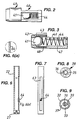
- An outlet valve arrangement 4 is installed in the root of the nozzle 3, and in this embodiment consists of a tubular valve housing 49 force-fitted into the pump body spigot 15.
- the valve casing 49 contains a ball 41 biased by a valve spring 44 towards a valve seat 42.
- the casing 49 is a generally tubular plastics unit to be fixed inside with the nozzle, having a cage portion 46 at the downstream end consisting substantially of window openings 47, a seat insert with a sharp-edged valve seat 42 fitted into the upstream end of the casing to trap the ball 41 and its biasing compression spring 44 inside, and a cylindrical tubular draw path conduit 43 with a closed wall extending downstream from the valve seat.
- the length of the draw path conduit 43 is slightly greater than the diameter of the ball 41, for example about 10mm.
- the fluid to be dispensed is a viscous one which may contain small particulates, so the sealing seat 42 is sharp-edged to avoid compromise of the seal by trapped particulates and some clearance is provided between the ball 41 and the tubular wall of the conduit 43 to prevent sticking.
- the difference in diameters is about 1.5mm in this embodiment.
- Fig 2 shows the outlet valve in its open position, where the ball 41 has been carried downstream by the product flow to beyond the end of the draw path conduit 43 and into the open cage 46 where product flows freely around it through the windows 47 and out along the nozzle 3.
- the spring 44 urges the ball back upstream (to the left, in the figure) and into the draw path conduit 43. From when it enters this conduit (the position shown in broken lines in Fig 3 ) until it meets the sealing seat 42 the moving ball 41 fits closely in the enclosure so as to draw a corresponding volume of product residue upstream along the nozzle 3 and push that volume back into the pump chamber.
- the nozzle 3 For free flow of a large dose the nozzle 3 is made wide and open, and contains more than can easily be withdrawn by the suck-back action of the outlet valve 4. Because of the upward inclination of the main run 31 of the nozzle, however, clearance of only the nozzle tip region is sufficient to prevent dripping. Nevertheless the wide cross-section at the nozzle tip in large dispensers makes this a demanding task for the suck-back arrangement and a special nozzle tip construction is adopted accordingly. Refer to Figs 1 , 8 and 9 .
- the nozzle tip has a separate moulded module 32 fitted onto the end of the main inclined run 31 of the nozzle.
- the nozzle tip module 32 has an integral internal partition tube 33 joined to the outer wall by a connecting fin 39 to divide the downwardly-directed tip portion of the passage into an inner tubular conduit 36 with upward convergence and an outer annular conduit 37.
- a rubber valve cap 34 fixed over the opening of the nozzle tip by means of a securing rim 38, has a thin rubber closure flap 35 extending in to close off the annular conduit 37 while leaving the central conduit 36 open. During dispensing the pressurised fluid flow easily forces the thin rubber flap 35 aside to exploit the main annular area of the nozzle opening for dispensing.
- the suck-back operation of the outlet valve 4 drives a small volume of product back into the pump chamber as the dispensing stroke finishes, at the same time as product is seeking to enter the pump chamber through the inlet valve.
- the plunger piston 23 has a special construction shown in more detail in Figs 4 and 5 .
- the piston 23 comprises a rigid outer annulus with a groove for the sealing ring 231 and a central plate 232 with a circular hole slidably receiving a terminal unit 26 of the plunger stem 22.
- the stem terminal unit 26 has a smaller diameter than the main stem 22 and end flange, so that the piston unit 23 is slidably axially movable between upper and lower stop surfaces 27 on these components.
- a generally circular rubber end diaphragm 24 is clamped by its peripheral bead 241 into a mounting groove around the rigid piston unit 23 and held in place there by a clamping ring 25.
- the diaphragm 24 covers the bottom end of the stem terminal 26, pressing resiliently up against it as seen in Fig 5.
- Fig 4 shows the rest configuration which the diaphragm 24 would adopt if the stem terminal were not there.
- the piston unit 23 is therefore biased against the lower stop surface 27 in the absence of other forces.
- a further benefit of the arrangement is that, at any position of the plunger, a small volume of material can be dispensed from the nozzle by small pushes on the plunger which advance the diaphragm 24 to displace 1 or 2ml from the pump without moving the main seal 231 against the cylinder wall .
- the dispenser pump includes means for signalling when the plunger passes a predetermined intermediate position so that the user can reliably dispense a partial dose of predetermined size.
- the generally cylindrical plunger stem 22 has an elongate axially-extending channel 63 extending down one side.
- the base of this channel has one or more small projecting lugs or pips 64 corresponding to predetermined plunger positions for dispensing a partial dose. Being recessed in the channel 63 these lugs 64 do not interfere with the movement of the stem through the cylinder guide sleeve 14.
- a clicker cap 61 is fitted over the top of the cylinder 13 as seen in Fig 1 and has a round central opening with at one side an inward resilient tongue 62 which projects into the plunger stem channel 63. As one of the lugs in the channel is drawn through the guide sleeve 14 it catches and raises the tongue 62 which then falls back with an audible click against the cylinder top, signalling to the user that the predetermined plunger height has been reached.
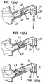
- Fig 10 shows a second embodiment differing with the respect to the deformable piston face, the suck-back arrangement at the outlet valve and the connection conduit 10.
- Fig 11 shows the insert casing 49 of the valve arrangement in detail.
- the tubular cylindrical casing 49 is substantially as before.
- the valve body 41 is in the form of a rod, eg of plastics material, fitting in the casing tube with some clearance and having a peripheral rubber sealing lip 411 around its front end to provide a close fit.
- the rod body has a larger-diameter front boss 412 to support a still larger circular rubber disc providing the sealing lip 411, and a long, straight rear part 413 which runs through a hole in the downstream end of the casing 49 to act as a guide.
- the biasing spring 44 fits around this rear part 413 and acts between the downstream end of the casing and the front boss 412 of the valve body 41.
- a stud 414 holds the rubber disc in place.
- Embodiments of the invention have been tried for dispensing viscous liquids containing particulates.
- first embodiment ( Fig 1 ) appreciable clearance was needed between the ball 41 and its casing to avoid sticking caused by the particulates.
- Good suck-back was nevertheless achieved because of the high viscosity of the liquid.
- the present embodiment is designed to deal with lower-viscosity liquids, which may nevertheless contain particulates.
- a radial rubber lip can provide a good seal for the fluid without sticking on the particulates.
- Figs 12 (a), (b), (c) show different states of the outlet valve.
- the product is being dispensed by pushing on the plunger.
- the flow of product pushes the valve shuttle body 41 back against its spring and escapes to discharge via the windows in the valve casing 49.
- the piston is released the outflow of liquid stops and the spring 44 pushes the shuttle body 41 back.
- Part way back its front seal 411 engages fittingly in the closed cylindrical draw path 43 of the valve casing and suck-back of the product from the nozzle tip proceeds.
- the nozzle flap valve 35 closes off the annular discharge passage portion when the piston is released, so the suck-back from the shuttle valve 41 easily clears the central passage portion 36 of the nozzle tip.
- the draw path 43 is dimensioned so that when the shuttle valve body 41 reaches the end of its stroke as seen in Fig 12(c) the liquid level in the nozzle will have fallen below the top of the tubular dividing wall 33 in the nozzle, preventing subsequent dripping.
- a further difference in the Fig 10 embodiment is that a spring 221 is provided to act axially between the plunger shaft 22 and the plunger end part 26 which pushes out the membrane 24. This supplements the restoring force of the membrane 24 making it possible to use a more flaccid membrane. It is easier to adjust the strength of a mechanical spring of this kind than to select a membrane shape and resilience which gives sufficient restoring force without tending to move the main seal 231 when spot-dosing.
- Another feature of the second embodiment is the special construction of the conduit 10.
- This is made from upper and lower moulded plastic shells 101, 102.
- the upper shell 101 - seen from beneath in Fig 13 - has an inverted bathtub form, the perpendicular tubular unions 104,105 for the pump inlet and fluid supply being easily formed integrally with the bathtub form by moulding.
- the longitudinal recess 107 of the bathtub form is likewise easily formed, and puts the unions 104, 105 in communication when the conduit 10 is closed by the lower shell 102.
- This is essentially a flat rectangular plate having a bonding border opposed to a corresponding bonding border on the upper shell 101 to form a continuous butted joint 103 between the two shells. This may be e.g. glued, ultrasonically bonded or hot-plate welded.
- Screw lugs 106 may be provided for securing the conduit 10 in relation to other elements of the dispensing system e.g. a box or housing (not shown).
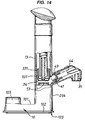
- Fig 14 is a corresponding cross-sectional view of a third embodiment, here showing the top shell 101 of the bridging conduit 10 formed as a one-piece entity with the inlet construction and body wall of the pump.
- a further feature in this embodiment is that the membrane 24 on the front of the plunger piston extends up around the sides of the piston's outer end unit with an annular projection to provide the primary piston seal 331 integrally.
- the casing 49 for the suck-back ball valve 41 has been formed integrally with the pump body shell and discharge nozzle wall, as an inner concentric cylindrical wall spaced from the outer wall of the discharge nozzle.
- the nozzle is a short one, so the reaction abutment for the biasing spring 44 is provided at the opposing end of the upwardly-inclined discharge passage, directly above the downward opening of the nozzle.
Landscapes
- Engineering & Computer Science (AREA)
- General Engineering & Computer Science (AREA)
- Mechanical Engineering (AREA)
- Physics & Mathematics (AREA)
- Fluid Mechanics (AREA)
- General Physics & Mathematics (AREA)
- Closures For Containers (AREA)
- Reciprocating Pumps (AREA)
- Organic Low-Molecular-Weight Compounds And Preparation Thereof (AREA)
- Details Of Reciprocating Pumps (AREA)
- Containers And Packaging Bodies Having A Special Means To Remove Contents (AREA)
Claims (17)
- Pompe de distributeur pour un matériau fluide comportant un corps de pompe (1) définissant une chambre de pompe à volume modifiable par l'action d'un plongeur à mouvement alternatif (2) qui fait fonctionner un piston (23) dans un vérin (13) du corps de pompe, le piston (23) établissant un joint de coulissement primaire (231) avec le vérin (13), une entrée de chambre de pompe (5) ayant une vanne d'entrée (53), une sortie de chambre de pompe ayant un agencement de vanne de sortie (4) et une buse d'évacuation (3) définissant un passage d'évacuation s'étendant en aval de l'agencement de vanne de sortie (4);
l'avancement de vanne de sortie (4) ayant un élément de blocage (41) qui est déplaçable le long du passage d'évacuation entre un état de vanne fermé à une position en amont et un état de vanne ouvert à une position en aval, l'agencement de vanne de sortie définissant un chemin de traction restreint (43) s'étendant le long du passage d'évacuation entre lesdites positions en amont et en aval et dimensionné pour être sensiblement bloqué par l'élément de blocage (41), et l'élément de blocage (41) étant sollicité vers la position en amont, pour le retour à celle-ci le long du chemin de traction (43) après la distribution pour ramener le matériau résiduel le long du passage d'évacuation;
caractérisé par
un élément de paroi résilient (24) dans la chambre de pompe apte à recevoir un volume correspondant au matériau ramené le long du passage d'évacuation par ledit élément de blocage sollicité après la distribution, sans nécessiter de reflux à l'entrée (5) ou un mouvement corporel du plongeur (2) qui fait glisser le joint primaire (231) de celui-ci dans le vérin. - Pompe de distributeur selon la revendication 1, dans laquelle l'agencement de vanne de sortie (4) comprend un boîtier de corps de vanne (49) ayant à son extrémité en amont un siège de scellement (42) pour un corps de vanne (41) qui constitue ledit élément de blocage, un conduit tubulaire renfermé s'étendant en aval du siège de scellement (42) pour réaliser un chemin de traction (43), et à son extrémité en aval une ou plusieurs ouvertures d'écoulement (47) communiquant le long du passage d'évacuation.
- Pompe de distributeur selon la revendication 1 ou la revendication 2, dans laquelle l'élément de blocage (41) est une balle.
- Pompe de distributeur selon la revendication 1 ou la revendication 2, dans laquelle l'élément de blocage (41) comprend un corps central rigide (412, 413) et une lèvre d'étanchéité périphérique flexible (411).
- Pompe de distributeur selon l'une quelconque des revendications 2, 3 et 4, dans laquelle le corps de vanne (41) est sollicité par un ressort de compression (44) disposé entre le corps de vanne et une butée de réaction en aval.
- Pompe de distributeur selon l'une quelconque des revendications précédentes, où la pompe n'a pas de moyen pour solliciter le plongeur (2) à nouveau à sa position étendue après la distribution de sorte que l'état de repos du plongeur est un état de volume bas de la chambre de pompe.
- Pompe de distributeur selon l'une quelconque des revendications précédentes, où ledit élément de paroi résilient (24) reçoit le volume retiré librement, c'est-à-dire sans résilience tendant à le solliciter à nouveau au-delà de l'agencement de vanne de sortie (4).
- Pompe de distributeur selon la revendication 7, dans laquelle ledit élément de paroi résilient est réalisé par ledit plongeur à mouvement alternatif (2) dont l'arbre possède une portion d'arbre annulaire externe (23) avec un joint de piston primaire (231) apte à coulisser contre une paroi cylindrique (13) du corps de pompe définissant la chambre de pompe, et une face d'extrémité ayant une portion centrale (27) qui, en exerçant une pression sur la tête (21) du plongeur, peut être avancée axialement relativement à la portion annulaire extérieure (23) du plongeur contre une force de rappel, l'arbre ayant une paroi de membrane flexible (24) réalisant un joint déformable qui reçoit le mouvement relatif entre lesdites portions extérieure et centrale (23, 27) de l'arbre.
- Pompe de distributeur selon la revendication 8, où ladite paroi de membrane flexible (24) se situe à ladite face d'extrémité de l'arbre de plongeur et est continue sur ladite portion centrale de celui-ci.
- Pompe de distributeur selon la revendication 8 ou 9, où un composant de tige (22) de l'arbre s'étend de la tête de plongeur (21) à ladite portion d'extrémité centrale (27).
- Pompe de distributeur selon la revendication 8, 9 ou 10, où l'arbre comprend un ressort hélicoïdal (221) agissant entre ladite portion d'arbre annulaire extérieure (23) et ladite portion centrale pouvant être avancée axialement (27) pour ramener la portion centrale (27) de la position axialement avancée.
- Pompe de distributeur selon l'une quelconque des revendications précédentes, où, relativement à la chambre de pompe, la buse d'évacuation (3) est fixée et fait saillie vers le côté, en menant le long d'une inclinaison vers le haut vers une ouverture de pointe dirigée vers le bas.
- Pompe de distributeur selon la revendication 12, où la pointe de buse (32) possède au moins une paroi de séparation longitudinale interne (33) divisant le passage d'évacuation en des portions de passage côte à côte (36, 37), au moins une portion de passage précitée (36) étant ouverte, et au moins une portion de passage précitée (37) étant fermée par un volet de fermeture déplaçable (35).
- Pompe de distributeur selon la revendication 13, où la paroi de division (33) est un conduit tubulaire définissant une portion de passage central ouverte (36)
entourée par une portion de passage annulaire (37) pouvant être fermée par un volet de fermeture annulaire déplaçable de manière résiliente (35). - Pompe de distributeur selon l'une quelconque des revendications précédentes, où la grandeur de la dose est au moins de 50 ml, et qui possède un plongeur vertical (2) sans ressort de rappel.
- Pompe de distributeur selon l'une quelconque des revendications précédentes, où le plongeur (2) comporte un arbre passant à travers une portion de guidage supérieure (14) du corps de pompe, et la portion de guidage comporte une formation de cliquet (62) pouvant être mise en prise avec une formation de cliquet (64) à une position intermédiaire sur l'arbre de piston (22) pour fournir un signal pouvant être ressenti par l'utilisateur lorsque la position intermédiaire de l'arbre passe à travers la portion de guidage (14) du corps de pompe.
- Pompe de distributeur selon l'une quelconque des revendications précédentes, où l'entrée de pompe (5) est dirigée vers le bas et communique avec un conduit de connection (10) pour ponter entre l'entrée de pompe (5) et une sortie de fourniture de fluide également dirigée vers le bas, un tel conduit de connection (10) étant formé par des portions de coque supérieure et inférieure (101, 102) qui sont reliées d'une manière étanche ensemble en se faisant face autour d'un seul joint limite, la portion de coque supérieure (101) ayant des première et seconde formations tubulaires dirigées vers le haut (104, 204; 105) pour l'entrée de pompe et la sortie de fourniture respectivement.
Applications Claiming Priority (3)
| Application Number | Priority Date | Filing Date | Title |
|---|---|---|---|
| GBGB9820962.0A GB9820962D0 (en) | 1998-09-25 | 1998-09-25 | Dispenser pumps |
| GB9820962 | 1998-09-25 | ||
| PCT/GB1999/003222 WO2000018513A1 (fr) | 1998-09-25 | 1999-09-27 | Pompes de distributeurs |
Publications (3)
| Publication Number | Publication Date |
|---|---|
| EP1115500A1 EP1115500A1 (fr) | 2001-07-18 |
| EP1115500B1 true EP1115500B1 (fr) | 2011-05-11 |
| EP1115500B8 EP1115500B8 (fr) | 2011-09-21 |
Family
ID=10839510
Family Applications (1)
| Application Number | Title | Priority Date | Filing Date |
|---|---|---|---|
| EP99947688A Expired - Lifetime EP1115500B8 (fr) | 1998-09-25 | 1999-09-27 | Pompes de distributeurs |
Country Status (7)
| Country | Link |
|---|---|
| US (1) | US6422434B1 (fr) |
| EP (1) | EP1115500B8 (fr) |
| JP (1) | JP2002525203A (fr) |
| AT (1) | ATE508805T1 (fr) |
| AU (1) | AU6106699A (fr) |
| GB (1) | GB9820962D0 (fr) |
| WO (1) | WO2000018513A1 (fr) |
Families Citing this family (24)
| Publication number | Priority date | Publication date | Assignee | Title |
|---|---|---|---|---|
| ATE273875T1 (de) * | 2000-09-05 | 2004-09-15 | Steinel Gmbh & Co Kg | Klebstoffkartusche |
| US6698629B2 (en) * | 2001-05-10 | 2004-03-02 | Shurflo Pump Manufacturing Co., Inc. | Comestible fluid dispensing tap and method |
| US6638039B1 (en) * | 2001-11-09 | 2003-10-28 | Wesley C. Saxton | Device for removing water from a pipe |
| US6540115B1 (en) * | 2001-11-19 | 2003-04-01 | Mituteru Watanabe | Seasoning container |
| US7601451B2 (en) * | 2004-05-11 | 2009-10-13 | Gm Global Technologies Operations, Inc. | Variable active area for fuel cell |
| US7654419B2 (en) * | 2004-09-17 | 2010-02-02 | Meadwestvaco Calmar, Inc. | Dispenser having elastomer discharge valve |
| US7328819B2 (en) | 2004-09-27 | 2008-02-12 | Kimberly-Clark Worldwide, Inc. | Self-contained liquid dispenser with a spray pump mechanism |
| US7431182B2 (en) * | 2004-11-20 | 2008-10-07 | Ciavarella Nick E | Dispenser with suction chamber |
| US20070029349A1 (en) * | 2005-08-05 | 2007-02-08 | Glen Jeffrey D | Multiple size-receiving toothpaste dispenser |
| DE102010045059A1 (de) | 2010-09-10 | 2012-03-15 | F. Holzer Gmbh | Dosiervorrichtung |
| JP5535155B2 (ja) * | 2011-09-05 | 2014-07-02 | 株式会社コガネイ | 流路切換弁およびそれを用いた流動性材料の吐出制御装置 |
| US8960507B2 (en) | 2011-10-25 | 2015-02-24 | Rieke Corporation | Pump dispenser with an inclined nozzle |
| JP5836065B2 (ja) * | 2011-10-28 | 2015-12-24 | 株式会社吉野工業所 | 吐出ポンプ |
| JP5820690B2 (ja) * | 2011-10-28 | 2015-11-24 | 株式会社吉野工業所 | 吐出ポンプ |
| US8955718B2 (en) * | 2012-10-31 | 2015-02-17 | Gojo Industries, Inc. | Foam pumps with lost motion and adjustable output foam pumps |
| WO2015048698A1 (fr) * | 2013-09-30 | 2015-04-02 | Gojo Industries, Inc | Distributeurs, unités de remplissage et pompes à caractéristiques d'aspiration inverse |
| CN108394638B (zh) * | 2017-02-07 | 2019-04-26 | 丁要武 | 按压泵 |
| CN108514994A (zh) * | 2018-06-25 | 2018-09-11 | 苏州赛姆西自动化设备有限公司 | 一种高速隔膜带回吸功能点胶阀 |
| CN115461158B (zh) | 2020-03-03 | 2025-03-04 | 里克包装系统有限公司 | 大容量往复式分配器 |
| CN113520139B (zh) * | 2020-04-21 | 2023-06-27 | 添可智能科技有限公司 | 供料装置及烹饪设备 |
| WO2022020688A1 (fr) * | 2020-07-24 | 2022-01-27 | H.J. Heinz Company Brands Llc | Distributeur de condiment |
| CN113926649B (zh) * | 2021-10-22 | 2022-09-06 | 中山市普隆半导体设备有限公司 | 一种点胶机用回吸式点胶阀 |
| JP2024100056A (ja) * | 2023-01-13 | 2024-07-26 | Towa株式会社 | 吐出装置、樹脂成形品の製造装置および樹脂成形品の製造方法 |
| CN118719448B (zh) * | 2024-06-21 | 2024-11-22 | 江苏福旭科技有限公司 | 一种硅单晶棒的均匀粘棒设备 |
Family Cites Families (8)
| Publication number | Priority date | Publication date | Assignee | Title |
|---|---|---|---|---|
| GB968290A (en) * | 1961-06-07 | 1964-09-02 | Maynard Charles Scott Cookson | Improvements in or relating to dispensers for syrups and like commodities |
| GB8527775D0 (en) * | 1985-11-11 | 1985-12-18 | English Glass Co Ltd | Dispenser pump |
| DE3901032C1 (fr) * | 1989-01-14 | 1990-02-08 | Danfoss A/S, Nordborg, Dk | |
| FR2651837B1 (fr) * | 1989-09-08 | 1993-04-23 | Aerosol Inventions Dev | Pompe manuelle pre-orientable sur le goulot d'un recipient. |
| GB9405891D0 (en) | 1994-03-24 | 1994-05-11 | English Glass Company The Limi | Dispenser pumps |
| US5549223A (en) * | 1994-08-03 | 1996-08-27 | Toyo Seikan Kaisha, Ltd. | Pump with back suction phase |
| US5556005A (en) * | 1995-01-09 | 1996-09-17 | Sprintvest Corporation Nv | Collapsible soap dispenser |
| DE69626092T2 (de) | 1995-12-15 | 2003-10-30 | Canyon Corp., Tokio/Tokyo | Spender mit Drückvorrichtung |
-
1998
- 1998-09-25 GB GBGB9820962.0A patent/GB9820962D0/en not_active Ceased
-
1999
- 1999-09-27 JP JP2000572024A patent/JP2002525203A/ja active Pending
- 1999-09-27 AT AT99947688T patent/ATE508805T1/de not_active IP Right Cessation
- 1999-09-27 US US09/787,836 patent/US6422434B1/en not_active Expired - Lifetime
- 1999-09-27 AU AU61066/99A patent/AU6106699A/en not_active Abandoned
- 1999-09-27 WO PCT/GB1999/003222 patent/WO2000018513A1/fr not_active Ceased
- 1999-09-27 EP EP99947688A patent/EP1115500B8/fr not_active Expired - Lifetime
Also Published As
| Publication number | Publication date |
|---|---|
| AU6106699A (en) | 2000-04-17 |
| GB9820962D0 (en) | 1998-11-18 |
| ATE508805T1 (de) | 2011-05-15 |
| US6422434B1 (en) | 2002-07-23 |
| JP2002525203A (ja) | 2002-08-13 |
| EP1115500A1 (fr) | 2001-07-18 |
| WO2000018513A1 (fr) | 2000-04-06 |
| EP1115500B8 (fr) | 2011-09-21 |
Similar Documents
| Publication | Publication Date | Title |
|---|---|---|
| EP1115500B1 (fr) | Pompes de distributeurs | |
| US5806721A (en) | Container mounted pump dispenser with back suction | |
| AU2011200143B2 (en) | Pump dispensers | |
| CA1296302C (fr) | Distributeur a plongeur vertical et a robinet a capsule | |
| EP2329231B1 (fr) | Dispositifs de dosage de liquide | |
| US4735347A (en) | Single puff atomizing pump dispenser | |
| US4696415A (en) | Apparatus for dispensing products from a self-sealing dispenser | |
| US5816453A (en) | Dispenser pump | |
| EP1388500B1 (fr) | Clapet de sortie pour pompe de distribution | |
| RU2627875C2 (ru) | Насосный дозатор | |
| WO2005049477A2 (fr) | Dispositifs de dosage de liquide | |
| JPS61174959A (ja) | 計量分配ポンプ | |
| CA2430419C (fr) | Pompes distributrices | |
| JP2010504852A (ja) | 液体ディスペンサ装置 | |
| EP1485308B1 (fr) | Distributeur d'un produit fluide | |
| US7523844B2 (en) | Fluid dispenser | |
| RU2407422C2 (ru) | Устройство для контролируемого дозирования пастообразной массы и контейнер такого устройства | |
| CN1010209B (zh) | 从自密封分配器中分配物料的装置 |
Legal Events
| Date | Code | Title | Description |
|---|---|---|---|
| PUAI | Public reference made under article 153(3) epc to a published international application that has entered the european phase |
Free format text: ORIGINAL CODE: 0009012 |
|
| 17P | Request for examination filed |
Effective date: 20010405 |
|
| AK | Designated contracting states |
Kind code of ref document: A1 Designated state(s): AT BE CH CY DE DK ES FI FR GB GR IE IT LI LU MC NL PT SE |
|
| AX | Request for extension of the european patent |
Free format text: AL;LT;LV;MK;RO;SI |
|
| 17Q | First examination report despatched |
Effective date: 20080225 |
|
| GRAP | Despatch of communication of intention to grant a patent |
Free format text: ORIGINAL CODE: EPIDOSNIGR1 |
|
| GRAS | Grant fee paid |
Free format text: ORIGINAL CODE: EPIDOSNIGR3 |
|
| GRAA | (expected) grant |
Free format text: ORIGINAL CODE: 0009210 |
|
| AK | Designated contracting states |
Kind code of ref document: B1 Designated state(s): AT BE CH CY DE DK ES FI FR GB GR IE IT LI LU MC NL PT SE |
|
| REG | Reference to a national code |
Ref country code: GB Ref legal event code: FG4D |
|
| REG | Reference to a national code |
Ref country code: CH Ref legal event code: EP |
|
| RAP2 | Party data changed (patent owner data changed or rights of a patent transferred) |
Owner name: REIKE CORPORATION |
|
| REG | Reference to a national code |
Ref country code: IE Ref legal event code: FG4D |
|
| REG | Reference to a national code |
Ref country code: DE Ref legal event code: R096 Ref document number: 69943424 Country of ref document: DE Effective date: 20110622 |
|
| REG | Reference to a national code |
Ref country code: NL Ref legal event code: VDEP Effective date: 20110511 |
|
| PG25 | Lapsed in a contracting state [announced via postgrant information from national office to epo] |
Ref country code: PT Free format text: LAPSE BECAUSE OF FAILURE TO SUBMIT A TRANSLATION OF THE DESCRIPTION OR TO PAY THE FEE WITHIN THE PRESCRIBED TIME-LIMIT Effective date: 20110912 Ref country code: SE Free format text: LAPSE BECAUSE OF FAILURE TO SUBMIT A TRANSLATION OF THE DESCRIPTION OR TO PAY THE FEE WITHIN THE PRESCRIBED TIME-LIMIT Effective date: 20110511 |
|
| PG25 | Lapsed in a contracting state [announced via postgrant information from national office to epo] |
Ref country code: ES Free format text: LAPSE BECAUSE OF FAILURE TO SUBMIT A TRANSLATION OF THE DESCRIPTION OR TO PAY THE FEE WITHIN THE PRESCRIBED TIME-LIMIT Effective date: 20110822 Ref country code: FI Free format text: LAPSE BECAUSE OF FAILURE TO SUBMIT A TRANSLATION OF THE DESCRIPTION OR TO PAY THE FEE WITHIN THE PRESCRIBED TIME-LIMIT Effective date: 20110511 Ref country code: CY Free format text: LAPSE BECAUSE OF FAILURE TO SUBMIT A TRANSLATION OF THE DESCRIPTION OR TO PAY THE FEE WITHIN THE PRESCRIBED TIME-LIMIT Effective date: 20110511 Ref country code: AT Free format text: LAPSE BECAUSE OF FAILURE TO SUBMIT A TRANSLATION OF THE DESCRIPTION OR TO PAY THE FEE WITHIN THE PRESCRIBED TIME-LIMIT Effective date: 20110511 Ref country code: BE Free format text: LAPSE BECAUSE OF FAILURE TO SUBMIT A TRANSLATION OF THE DESCRIPTION OR TO PAY THE FEE WITHIN THE PRESCRIBED TIME-LIMIT Effective date: 20110511 Ref country code: GR Free format text: LAPSE BECAUSE OF FAILURE TO SUBMIT A TRANSLATION OF THE DESCRIPTION OR TO PAY THE FEE WITHIN THE PRESCRIBED TIME-LIMIT Effective date: 20110812 |
|
| PG25 | Lapsed in a contracting state [announced via postgrant information from national office to epo] |
Ref country code: NL Free format text: LAPSE BECAUSE OF FAILURE TO SUBMIT A TRANSLATION OF THE DESCRIPTION OR TO PAY THE FEE WITHIN THE PRESCRIBED TIME-LIMIT Effective date: 20110511 |
|
| REG | Reference to a national code |
Ref country code: DE Ref legal event code: R081 Ref document number: 69943424 Country of ref document: DE Owner name: RIEKE CORPORATION, AUBURN, US Free format text: FORMER OWNER: RIEKE PACKAGING SYSTEMS LTD., LEICESTER, LEICESTERSHIRE, GB Effective date: 20111201 |
|
| PG25 | Lapsed in a contracting state [announced via postgrant information from national office to epo] |
Ref country code: DK Free format text: LAPSE BECAUSE OF FAILURE TO SUBMIT A TRANSLATION OF THE DESCRIPTION OR TO PAY THE FEE WITHIN THE PRESCRIBED TIME-LIMIT Effective date: 20110511 |
|
| PLBE | No opposition filed within time limit |
Free format text: ORIGINAL CODE: 0009261 |
|
| STAA | Information on the status of an ep patent application or granted ep patent |
Free format text: STATUS: NO OPPOSITION FILED WITHIN TIME LIMIT |
|
| 26N | No opposition filed |
Effective date: 20120214 |
|
| PG25 | Lapsed in a contracting state [announced via postgrant information from national office to epo] |
Ref country code: MC Free format text: LAPSE BECAUSE OF NON-PAYMENT OF DUE FEES Effective date: 20110930 |
|
| REG | Reference to a national code |
Ref country code: CH Ref legal event code: PL |
|
| PG25 | Lapsed in a contracting state [announced via postgrant information from national office to epo] |
Ref country code: IT Free format text: LAPSE BECAUSE OF FAILURE TO SUBMIT A TRANSLATION OF THE DESCRIPTION OR TO PAY THE FEE WITHIN THE PRESCRIBED TIME-LIMIT Effective date: 20110511 |
|
| REG | Reference to a national code |
Ref country code: DE Ref legal event code: R097 Ref document number: 69943424 Country of ref document: DE Effective date: 20120214 |
|
| REG | Reference to a national code |
Ref country code: IE Ref legal event code: MM4A |
|
| PG25 | Lapsed in a contracting state [announced via postgrant information from national office to epo] |
Ref country code: LI Free format text: LAPSE BECAUSE OF NON-PAYMENT OF DUE FEES Effective date: 20110930 Ref country code: IE Free format text: LAPSE BECAUSE OF NON-PAYMENT OF DUE FEES Effective date: 20110927 Ref country code: CH Free format text: LAPSE BECAUSE OF NON-PAYMENT OF DUE FEES Effective date: 20110930 |
|
| PG25 | Lapsed in a contracting state [announced via postgrant information from national office to epo] |
Ref country code: LU Free format text: LAPSE BECAUSE OF NON-PAYMENT OF DUE FEES Effective date: 20110927 |
|
| REG | Reference to a national code |
Ref country code: FR Ref legal event code: PLFP Year of fee payment: 18 |
|
| REG | Reference to a national code |
Ref country code: FR Ref legal event code: PLFP Year of fee payment: 19 |
|
| REG | Reference to a national code |
Ref country code: FR Ref legal event code: PLFP Year of fee payment: 20 |
|
| PGFP | Annual fee paid to national office [announced via postgrant information from national office to epo] |
Ref country code: DE Payment date: 20180927 Year of fee payment: 20 Ref country code: FR Payment date: 20180925 Year of fee payment: 20 |
|
| PGFP | Annual fee paid to national office [announced via postgrant information from national office to epo] |
Ref country code: GB Payment date: 20180927 Year of fee payment: 20 |
|
| REG | Reference to a national code |
Ref country code: DE Ref legal event code: R071 Ref document number: 69943424 Country of ref document: DE |
|
| REG | Reference to a national code |
Ref country code: GB Ref legal event code: PE20 Expiry date: 20190926 |
|
| PG25 | Lapsed in a contracting state [announced via postgrant information from national office to epo] |
Ref country code: GB Free format text: LAPSE BECAUSE OF EXPIRATION OF PROTECTION Effective date: 20190926 |