EP1115517B1 - Greifer zum wechseln von biegewerkzeugen für eine rohrbiegemaschine - Google Patents
Greifer zum wechseln von biegewerkzeugen für eine rohrbiegemaschine Download PDFInfo
- Publication number
- EP1115517B1 EP1115517B1 EP99943012A EP99943012A EP1115517B1 EP 1115517 B1 EP1115517 B1 EP 1115517B1 EP 99943012 A EP99943012 A EP 99943012A EP 99943012 A EP99943012 A EP 99943012A EP 1115517 B1 EP1115517 B1 EP 1115517B1
- Authority
- EP
- European Patent Office
- Prior art keywords
- bending
- grasping device
- horizontal
- rotary head
- secured
- Prior art date
- Legal status (The legal status is an assumption and is not a legal conclusion. Google has not performed a legal analysis and makes no representation as to the accuracy of the status listed.)
- Expired - Lifetime
Links
- 238000005452 bending Methods 0.000 title claims abstract description 92
- 230000001419 dependent effect Effects 0.000 claims description 4
- 238000006073 displacement reaction Methods 0.000 description 5
- 240000007817 Olea europaea Species 0.000 description 1
- 238000013459 approach Methods 0.000 description 1
- 238000007373 indentation Methods 0.000 description 1
- 238000009434 installation Methods 0.000 description 1
- 230000002093 peripheral effect Effects 0.000 description 1
- 238000007493 shaping process Methods 0.000 description 1
Images



Classifications
-
- B—PERFORMING OPERATIONS; TRANSPORTING
- B23—MACHINE TOOLS; METAL-WORKING NOT OTHERWISE PROVIDED FOR
- B23Q—DETAILS, COMPONENTS, OR ACCESSORIES FOR MACHINE TOOLS, e.g. ARRANGEMENTS FOR COPYING OR CONTROLLING; MACHINE TOOLS IN GENERAL CHARACTERISED BY THE CONSTRUCTION OF PARTICULAR DETAILS OR COMPONENTS; COMBINATIONS OR ASSOCIATIONS OF METAL-WORKING MACHINES, NOT DIRECTED TO A PARTICULAR RESULT
- B23Q3/00—Devices holding, supporting, or positioning work or tools, of a kind normally removable from the machine
- B23Q3/155—Arrangements for automatic insertion or removal of tools, e.g. combined with manual handling
- B23Q3/1556—Arrangements for automatic insertion or removal of tools, e.g. combined with manual handling of non-rotary tools
- B23Q3/15573—Arrangements for automatic insertion or removal of tools, e.g. combined with manual handling of non-rotary tools the tool being taken from a storage device and transferred to a tool holder by means of transfer devices
-
- B—PERFORMING OPERATIONS; TRANSPORTING
- B21—MECHANICAL METAL-WORKING WITHOUT ESSENTIALLY REMOVING MATERIAL; PUNCHING METAL
- B21D—WORKING OR PROCESSING OF SHEET METAL OR METAL TUBES, RODS OR PROFILES WITHOUT ESSENTIALLY REMOVING MATERIAL; PUNCHING METAL
- B21D37/00—Tools as parts of machines covered by this subclass
- B21D37/14—Particular arrangements for handling and holding in place complete dies
-
- B—PERFORMING OPERATIONS; TRANSPORTING
- B21—MECHANICAL METAL-WORKING WITHOUT ESSENTIALLY REMOVING MATERIAL; PUNCHING METAL
- B21D—WORKING OR PROCESSING OF SHEET METAL OR METAL TUBES, RODS OR PROFILES WITHOUT ESSENTIALLY REMOVING MATERIAL; PUNCHING METAL
- B21D7/00—Bending rods, profiles, or tubes
- B21D7/02—Bending rods, profiles, or tubes over a stationary forming member; by use of a swinging forming member or abutment
- B21D7/024—Bending rods, profiles, or tubes over a stationary forming member; by use of a swinging forming member or abutment by a swinging forming member
-
- B—PERFORMING OPERATIONS; TRANSPORTING
- B21—MECHANICAL METAL-WORKING WITHOUT ESSENTIALLY REMOVING MATERIAL; PUNCHING METAL
- B21D—WORKING OR PROCESSING OF SHEET METAL OR METAL TUBES, RODS OR PROFILES WITHOUT ESSENTIALLY REMOVING MATERIAL; PUNCHING METAL
- B21D7/00—Bending rods, profiles, or tubes
- B21D7/16—Auxiliary equipment, e.g. for heating or cooling of bends
-
- Y—GENERAL TAGGING OF NEW TECHNOLOGICAL DEVELOPMENTS; GENERAL TAGGING OF CROSS-SECTIONAL TECHNOLOGIES SPANNING OVER SEVERAL SECTIONS OF THE IPC; TECHNICAL SUBJECTS COVERED BY FORMER USPC CROSS-REFERENCE ART COLLECTIONS [XRACs] AND DIGESTS
- Y10—TECHNICAL SUBJECTS COVERED BY FORMER USPC
- Y10S—TECHNICAL SUBJECTS COVERED BY FORMER USPC CROSS-REFERENCE ART COLLECTIONS [XRACs] AND DIGESTS
- Y10S483/00—Tool changing
- Y10S483/902—Tool grippers
-
- Y—GENERAL TAGGING OF NEW TECHNOLOGICAL DEVELOPMENTS; GENERAL TAGGING OF CROSS-SECTIONAL TECHNOLOGIES SPANNING OVER SEVERAL SECTIONS OF THE IPC; TECHNICAL SUBJECTS COVERED BY FORMER USPC CROSS-REFERENCE ART COLLECTIONS [XRACs] AND DIGESTS
- Y10—TECHNICAL SUBJECTS COVERED BY FORMER USPC
- Y10T—TECHNICAL SUBJECTS COVERED BY FORMER US CLASSIFICATION
- Y10T483/00—Tool changing
- Y10T483/17—Tool changing including machine tool or component
- Y10T483/1729—Reciprocating tool machine tool [e.g., broaching machine, shaping machine, etc.]
- Y10T483/1731—Reciprocating tool machine tool [e.g., broaching machine, shaping machine, etc.] including matrix
-
- Y—GENERAL TAGGING OF NEW TECHNOLOGICAL DEVELOPMENTS; GENERAL TAGGING OF CROSS-SECTIONAL TECHNOLOGIES SPANNING OVER SEVERAL SECTIONS OF THE IPC; TECHNICAL SUBJECTS COVERED BY FORMER USPC CROSS-REFERENCE ART COLLECTIONS [XRACs] AND DIGESTS
- Y10—TECHNICAL SUBJECTS COVERED BY FORMER USPC
- Y10T—TECHNICAL SUBJECTS COVERED BY FORMER US CLASSIFICATION
- Y10T483/00—Tool changing
- Y10T483/17—Tool changing including machine tool or component
- Y10T483/1733—Rotary spindle machine tool [e.g., milling machine, boring, machine, grinding machine, etc.]
- Y10T483/1748—Tool changer between spindle and matrix
- Y10T483/1752—Tool changer between spindle and matrix including tool holder pivotable about axis
- Y10T483/1755—Plural tool holders pivotable about common axis
- Y10T483/1767—Linearly movable tool holders
-
- Y—GENERAL TAGGING OF NEW TECHNOLOGICAL DEVELOPMENTS; GENERAL TAGGING OF CROSS-SECTIONAL TECHNOLOGIES SPANNING OVER SEVERAL SECTIONS OF THE IPC; TECHNICAL SUBJECTS COVERED BY FORMER USPC CROSS-REFERENCE ART COLLECTIONS [XRACs] AND DIGESTS
- Y10—TECHNICAL SUBJECTS COVERED BY FORMER USPC
- Y10T—TECHNICAL SUBJECTS COVERED BY FORMER US CLASSIFICATION
- Y10T483/00—Tool changing
- Y10T483/18—Tool transfer to or from matrix
- Y10T483/1809—Matrix including means to latch tool
Definitions
- the present invention relates to a gripping device for changing bending tools on a standard tube bending machine.
- the machine for bending tubes (described in patent application FR 98 01315) is secured to the bending arm of the barrel device carrying sets of jaws for clamping different impressions.
- Each set of clamping jaws is made up a fixed jaw and a movable jaw allowing the production of an elbow, the bending radius is special.
- Barrel device can rotate at the same time time for the bending arm around the bending head to complete the setting shaped tubes.
- the barrel device can move, on the one hand in rotation around its own longitudinal axis, and on the other hand in directions included in planes perpendicular and / or parallel to that containing the longitudinal axis of the fixed frame.
- the purpose of the gripping device according to the present invention is to come fit around a standard type tube bending machine without modify the structure and operation.
- the gripping device is not integral with the bending head of the bend, it is independent and placed around it so that it can during the tube bending cycle time, change tools or clearances clamping jaws.
- FIG. 1 and 2 show a standard type bending machine 1 comprising a fixed frame 2 which carries at one of its ends a bending head 3 around which a bending arm 4 pivots, and a gripping device 5 for changing the bending tools which is arranged above said machine and at the bending head 3.
- the fixed frame 2 comprises in the known manner, and along its longitudinal axis, a guide rail on which slides a carriage 6 which approaches and moves away from the bending head 3.
- the carriage 6 includes a mandrel 7 for receiving and guiding a bending tube, not shown, which is moved in translation and in rotation about its axis.
- a device 8 also slides on the longitudinal rail of the fixed frame 2 to avoid, by means of an olive, the crushing of the tube during its bending.
- the bending arm 4 comprises a jaw support 9 which moves horizontally towards the bending head 3 via hydraulic or pneumatic or electric devices known per se.
- the jaw support 9 has on its vertical edge 10, located opposite the bending head 3, a T-shaped groove 11, or the like, which is provided for receiving an intermediate element 12 intended to cooperate with the movable jaw 13 clamping jaw set 14.
- the bending head 3 is integral with a bending roller 15, or forming roller, on which is fixed to the fixed jaw 16 of the set of clamping jaws 14.
- the bending roller 15 has a circular profile, part of which is cut out to form an L-shaped notch allowing the positioning of the fixed jaw 16 of the clamping jaw set 14.
- the bending roller 15 comprises in the known manner, a groove peripheral which communicates with the imprint of the fixed jaw 16, and whose radius bending may vary depending on the shaping to be performed on the tube.
- the bending head 3 includes displacement means to be able to move horizontally and vertically relative to the fixed frame 2, i.e. in directions lying in planes perpendicular to that containing the longitudinal axis of the machine 1 or of the fixed frame 2.
- the gripping device 5 for changing the bending tools or sets clamping jaw 14 is placed around and above the bending machine 1.
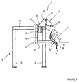
- FIGs 3 to 5 we have shown the gripping device 5 which consists of a portal frame 17 or the like comprising vertical feet 18 to 21 interconnected in the upper part of the gantry 17 by horizontal beams 22 to 25. It is obvious that the portal 17 can be replaced by any other structure equivalent without changing the subject of the invention.
- the horizontal beam 22 of the gantry 17 is integral, inside the space defined by horizontal beams 22 to 25, guide means 26 which cooperate with a cross member 27 parallel to said beam 22 and capable of being move in a horizontal direction relative to said gantry.
- the cross member 27 has on its face opposite to that cooperating with the means guide 26, a guide device 28 which is connected to vertical guides and parallel 29 and 30, integral with a support 31 so that the latter can move in a vertical direction relative to the gantry 17.
- the support 31 is perpendicularly integral with its vertical axis and in its lower part of a horizontal beam 32, carrying a head at its free end rotary 33 constituting the gripping means of tools or sets of jaws clamp 14.
- the rotary head 33 consists of an arm 34 which can rotate about an axis central 35 which is integral with the horizontal beam 32 of the support 31.
- the axis central unit 35 is inclined at an angle ⁇ of approximately 45 ° degrees relative to the plane horizontal containing beam 32.
- the inclination of the axis of rotation 35 makes it possible to arrange the arm 34 of the head rotary 33 in an inclined plane with respect to that horizontal of the beam 32.
- This inclination of the rotary head 33 by an angle ⁇ releases a large volume around the bending head 3 of the machine 1, making it possible to free up a space for handling the tube already bent, without the latter coming up against against the rotating head.
- the arm 34 is secured at each of its ends to a pivot axis 36, 37 which is arranged in a horizontal plane and parallel to that containing the beam 32.
- Each axis 36, 37 cooperates with a fixing device 38, 39 which can pivot around its respective axis 36, 37 to come in a vertical plane and parallel to the one containing the support 31.
- Each fixing device 38, 39 carries a set of clamping jaws 14 which is consisting of a movable jaw 13 and a fixed jaw 16 provided for indexing respectively on the intermediate element 12 of the jaw support 9 secured to the bending arm 4 and on the bending roller 15 of the bending head 3 of the bending machine 1 (figure 2).
- the horizontal beam 22 of the gantry 17 is secured above the means of guide 26 of a horizontal crosspiece 40 provided with guide means 41 allowing the sliding or rotation of a tool magazine 42 parallel to beam 22.
- the tool magazine 42 includes sets of clamping jaws 14 comprising each a movable jaw 13 and a fixed jaw 16.
- the sets of clamping jaws 14 have indentations with different bending radii for allow on the same bending machine 1 to produce on the same tube several bending.
- the tool magazine 42 can also carry integral bending rollers 15 fixed jaw 16 constituting a monobloc tool and movable jaws 13 forming clamping jaw sets 14.
- the tool magazine 42 is controlled by a central unit, not shown, which is independent or identical to that controlling the bending machine 1.
- the head 33 has combined movements which are consisting of two independent or dependent rotations arranged in different planes, of a vertical movement with respect to gantry 17 thanks to the displacement of the support 31, and a horizontal movement relative to the gantry 17 via the cross member 27.
- the bending arm 4, and more particularly the jaw support 9, carries via element 12, a movable jaw 13, while the roller bending 15 cooperates with a movable jaw 16 forming a first set of jaws of tightening 14 which made it possible to bend the tube.
- the gripping device 5 presents by a horizontal movement of the cross-member 27, the rotary head 33 above the bending head 3 and the bending arm 4.
- the rotary head 33 has its fixing device 39 which is empty and previously positioned in a vertical direction by pivoting around the axis 37 above the movable 13 and fixed jaws 16 of the first set of jaws of tightening 14.
- the rotary head 33 recovers, by a vertical downward movement of the support 31, on its fixing device 39 the movable 13 and fixed jaws 16 of the first set clamping jaws 14 by snap-fastening or any other similar fixing means.
- the rotary head 33 rises by a vertical displacement of the support 31 relative to at gantry 17 to extract movable 13 and fixed jaws 16 from the element intermediate 12 and the bending roller 15.
- the head 33 pivots around its central axis 35 by a half-turn to present above of the bending head 3 and the bending arm 4, a new set of jaws clamp 14 carried by the fixing device 38.
- the latter is placed in a vertical position by pivoting about its axis 36 so that the jaws mobile 13 and fixed 16 of the new set of clamping jaws 14 are in the same vertical plane as the bending head 3 and the bending arm 4.
- the rotary head 33 descends via the support 31 to bring the new set of clamping jaws 14 and respectively the movable jaws 13 in the intermediate element 12 of the bending arm 4 and the fixed jaw 16 in the notch of the bending roller 15 of the bending head 3.
- the movable and fixed jaws 13 of the new set of clamping jaws 14 are unlocked from the fixing device 38 by pneumatic means or analogs, not shown, and separated from the fixing device 38 which is located free and without set of clamping jaws when reassembling the rotary head 33.
- the magazine 42 moves horizontally on the beam 22 of the gantry 17 to present in the axis of the rotary head 33, and more particularly opposite the fixing device 39, an empty receiving housing clamping jaw clearance 14.
- the rotary head 33 rises vertically by means of the support 31 relative to the gantry 17 enabling the first set of clamping jaws 14 to be put in place, secured to the fixing device 39 in the empty housing selected in the store 42.
- the rotary head 33 descends vertically thanks to the support 31 to let the sets of clamping jaws 14 in magazine 42 and release the fixing device 39.
- the magazine 42 again moves horizontally on the beam 22 to present in front of the fixing device 39 another set of clamping jaws 14.
- the rotary head 33 rises to fix the other set of jaws on the device 39 clamping 14, while the fixing device 38 is free and without tools.
- the bend 1 proceeds to shape an elbow on the tube by means of the set of clamping jaw arranged by the fixing device 38.
Landscapes
- Engineering & Computer Science (AREA)
- Mechanical Engineering (AREA)
- Bending Of Plates, Rods, And Pipes (AREA)
Claims (11)
- Greifvorrichtung zum Wechseln von Biegewerkzeugen an einer standardmäßigen Rohrbiegemaschine, dadurch gekennzeichnet, daß sie folgendes umfaßt:einen um die Biegemaschine (1) herum über dem Biegekopf (3) und dem Biegearm (4) angeordneten Tragrahmen (17) oder dergleichen;einen Drehkopf (33), der bezüglich des Tragrahmens (17) unabhängige Bewegungen aufweist, die aus zwei unabhängigen oder abhängigen Drehungen in verschiedenen Ebenen, einer Vertikalbewegung und einer Horizontalbewegung bestehen;und ein Werkzeugmagazin (42), das sich unabhängig von den Bewegungen des Drehkopfs (33) in einer Horizontal- oder Drehrichtung bezüglich des Tragrahmens (17) bewegen kann.
- Greifvorrichtung nach Anspruch 1, dadurch gekennzeichnet, daß der Drehkopf (33) um eine in einem Winkel (α) zu einer horizontalen Ebene geneigte mittlere Achse (35) schwenkt.
- Greifvorrichtung nach Anspruch 2, dadurch gekennzeichnet, daß der Winkel (α) 45° zur horizontalen Ebene beträgt.
- Greifvorrichtung nach Anspruch 1, dadurch gekennzeichnet, daß der Tragrahmen (17) aus vier vertikalen Füßen (18 bis 21) besteht, die im oberen Teil durch vier horizontale Träger (22 bis 25) miteinander verbunden sind, welche so angeordnet sind, daß der Träger (22) den Drehkopf (33) und das Werkzeugmagazin (42) trägt.
- Greifvorrichtung nach Anspruch 4, dadurch gekennzeichnet, daß der horizontale Träger (22) mit Führungsmitteln (26) fest verbunden ist, die mit einem sich parallel zum Träger (22) erstreckenden Querträger (27) zusammenwirken und sich in einer horizontalen Richtung bezüglich des Tragrahmens (17) bewegen können, wobei der Querträger (27) an seiner Fläche, die der mit den Führungsmitteln (26) zusammenwirkenden Fläche gegenüberliegt, eine Führungsvorrichtung (28) aufweist, die es einer Stütze (31) gestattet, sich in einer vertikalen Richtung bezüglich des Tragrahmens (17) zu bewegen, wobei die Stütze (31) senkrecht zu ihrer vertikalen Achse und in ihrem unteren Teil mit einem horizontalen Träger (32) fest verbunden ist, der an seinem freien Ende den Drehkopf (33) trägt, der die Mittel zum Ergreifen der Werkzeuge oder Spannbackensätze (14) bildet.
- Greifvorrichtung nach Anspruch 2, dadurch gekennzeichnet, daß der Drehkopf (33) aus einem Arm (34) besteht, der sich um die mittlere Achse (35) drehen kann, die mit dem horizontalen Träger (32) der Stütze (31) fest verbunden ist.
- Greifvorrichtung nach Anspruch 6, dadurch gekennzeichnet, daß der Arm (34) an jedem seiner Enden mit einer Schwenkachse (36, 37) fest verbunden ist, die jeweils mit einer Befestigungsvorrichtung (38, 39) zusammenwirken, die um ihre jeweilige Achse schwenken, um in eine Ebene zu gelangen, die vertikal und parallel zu der die Stütze (31) enthaltenden verläuft.
- Greifvorrichtung nach Anspruch 7, dadurch gekennzeichnet, daß jede Befestigungsvorrichtung (38, 39) zum Tragen eines Spannbackensatzes (14) vorgesehen ist, der aus einer beweglichen Spannbacke (13) und einer feststehenden Spannbacke (16) besteht, die am Zwischenelement (12) des mit dem Biegearm (4) fest verbundenen Spannbackenträgers (9) bzw. an der Biegewalze (15) des Biegekopfs (3) der Biegemaschine (1) verrastet sind.
- Greifvorrichtung nach Anspruch 7, dadurch gekennzeichnet, daß der Arm (34) an jedem seiner Enden mit einer Schwenkachse (36, 37) fest verbunden ist, die in einer Ebene angeordnet ist, welche horizontal und parallel zu der den Träger (32) enthaltenden verläuft.
- Greifvorrichtung nach Anspruch 4, dadurch gekennzeichnet, daß der horizontale Träger (22) über den Führungsmitteln (26) mit einem horizontalen Querträger (40) fest verbunden ist, der mit Führungsmitteln (41) versehen ist, die die Verschiebung oder Drehung des Werkzeugmagazins (42) gestatten.
- Greifvorrichtung nach Anspruch 8, dadurch gekennzeichnet, daß jeder Spannbackensatz (14) aus einer beweglichen Spannbacke (13) und einem einstückigen Werkzeug besteht, das durch die Biegewalze (15) gebildet wird, an der die feste Spannbacke (16) befestigt ist.
Applications Claiming Priority (3)
| Application Number | Priority Date | Filing Date | Title |
|---|---|---|---|
| FR9811981 | 1998-09-22 | ||
| FR9811981A FR2783447B1 (fr) | 1998-09-22 | 1998-09-22 | Dispositif prehenseur pour le changement des outils de cintrage sur une machine a cintrer les tubes |
| PCT/FR1999/002235 WO2000016922A1 (fr) | 1998-09-22 | 1999-09-21 | Dispositif prehenseur pour le changement des outils de cintrage sur une machine a cintrer les tubes |
Publications (2)
| Publication Number | Publication Date |
|---|---|
| EP1115517A1 EP1115517A1 (de) | 2001-07-18 |
| EP1115517B1 true EP1115517B1 (de) | 2002-04-17 |
Family
ID=9530824
Family Applications (1)
| Application Number | Title | Priority Date | Filing Date |
|---|---|---|---|
| EP99943012A Expired - Lifetime EP1115517B1 (de) | 1998-09-22 | 1999-09-21 | Greifer zum wechseln von biegewerkzeugen für eine rohrbiegemaschine |
Country Status (7)
| Country | Link |
|---|---|
| US (1) | US6416449B1 (de) |
| EP (1) | EP1115517B1 (de) |
| AT (1) | ATE216291T1 (de) |
| CA (1) | CA2342731A1 (de) |
| DE (1) | DE69901310T2 (de) |
| FR (1) | FR2783447B1 (de) |
| WO (1) | WO2000016922A1 (de) |
Cited By (1)
| Publication number | Priority date | Publication date | Assignee | Title |
|---|---|---|---|---|
| CN110774006A (zh) * | 2019-11-13 | 2020-02-11 | 陈春 | 一种g型卡自动成型设备 |
Families Citing this family (10)
| Publication number | Priority date | Publication date | Assignee | Title |
|---|---|---|---|---|
| DE102005012551B4 (de) * | 2005-03-18 | 2008-06-12 | Tracto-Technik Gmbh | Wechselvorrichtung für ein Biegemaschinensystem sowie ein Biegemaschinensystem und ein Verfahren zum Umrüsten einer Biegemaschine |
| CN100427255C (zh) * | 2005-09-01 | 2008-10-22 | 王宁 | 双支承刨床 |
| DE202007015831U1 (de) * | 2007-11-13 | 2009-03-26 | Wilhelm Karmann Gmbh | Arbeitsstation zur Bearbeitung eines Werkstücks, insbesondere eines Gestängeelementes eines Verdeckgestänges eines Cabriolet-Fahrzeugs |
| DE102010050544A1 (de) * | 2010-11-09 | 2012-05-10 | Carl Zeiss Industrielle Messtechnik Gmbh | Halterung zum Halten eines Sensors für ein Koordinatenmessgerät |
| FR3001163B1 (fr) * | 2013-01-21 | 2015-05-01 | Eaton Leonard Europ | Dispositif de cintrage de profiles tels que des tubes |
| FR3007301B1 (fr) * | 2013-06-25 | 2015-06-05 | Financ Jaubert | Machine a cintrer un profile |
| FR3037828A1 (fr) * | 2015-06-24 | 2016-12-30 | Eaton Leonard Group | Dispositif de cintrage et de decoupe de profiles tels que des tubes |
| CN105328254B (zh) * | 2015-12-14 | 2018-01-02 | 安徽省辉煌机械制造有限公司 | 一种龙门刨床 |
| CN106514261B (zh) * | 2016-12-20 | 2018-09-21 | 安徽汉采密封件科技有限公司 | 铣削设备 |
| CN113015584A (zh) * | 2018-08-28 | 2021-06-22 | 安大略模具国际公司 | 用于将金属条成形为模具的系统、装置和方法 |
Family Cites Families (12)
| Publication number | Priority date | Publication date | Assignee | Title |
|---|---|---|---|---|
| US3808856A (en) * | 1970-08-03 | 1974-05-07 | B Lance | Tube bending apparatus |
| US4355525A (en) * | 1979-09-04 | 1982-10-26 | Carson James W | Production tube bending machine |
| DE3471892D1 (en) * | 1983-03-26 | 1988-07-14 | Schwarze Rigobert | Tube bending machine |
| US4599786A (en) * | 1984-09-04 | 1986-07-15 | Cincinnati Milacron Inc. | Grinding machine with apparatus for changing grinding wheel tools and workpieces |
| US4649622A (en) * | 1984-09-04 | 1987-03-17 | W. A. Whitney Corp. | Tool changing apparatus for a punch press |
| US4967585A (en) * | 1989-06-12 | 1990-11-06 | Samuel Grimaldo | Bending die and ram assembly for tube bending machine |
| US4996861A (en) * | 1990-02-08 | 1991-03-05 | Stern/Leach Company | Apparatus for forming an elogated tubular element into a helix |
| FR2668730B1 (fr) * | 1990-11-07 | 1995-05-05 | Brisard Machines Outils | Dispositif et procede de changement d'outils sur machine-outils a portique mobile. |
| US5407415A (en) * | 1993-01-21 | 1995-04-18 | The Boeing Company | Automated composite trim workstation |
| SE9403211L (sv) * | 1994-09-23 | 1996-03-24 | Asea Brown Boveri | Robotanläggning |
| US5979204A (en) * | 1996-07-01 | 1999-11-09 | Tools For Bending, Inc. | Quick change tooling method and apparatus |
| US6254317B1 (en) * | 1999-09-10 | 2001-07-03 | Northrop Grumman Corporation | Triple gantry drilling system |
-
1998
- 1998-09-22 FR FR9811981A patent/FR2783447B1/fr not_active Expired - Fee Related
-
1999
- 1999-09-21 US US09/787,696 patent/US6416449B1/en not_active Expired - Fee Related
- 1999-09-21 EP EP99943012A patent/EP1115517B1/de not_active Expired - Lifetime
- 1999-09-21 AT AT99943012T patent/ATE216291T1/de active
- 1999-09-21 DE DE69901310T patent/DE69901310T2/de not_active Expired - Fee Related
- 1999-09-21 WO PCT/FR1999/002235 patent/WO2000016922A1/fr not_active Ceased
- 1999-09-21 CA CA002342731A patent/CA2342731A1/fr not_active Abandoned
Cited By (2)
| Publication number | Priority date | Publication date | Assignee | Title |
|---|---|---|---|---|
| CN110774006A (zh) * | 2019-11-13 | 2020-02-11 | 陈春 | 一种g型卡自动成型设备 |
| CN110774006B (zh) * | 2019-11-13 | 2021-06-25 | 兴宁市奥浦合金工业有限公司 | 一种g型卡自动成型设备 |
Also Published As
| Publication number | Publication date |
|---|---|
| US6416449B1 (en) | 2002-07-09 |
| DE69901310D1 (de) | 2002-05-23 |
| WO2000016922A1 (fr) | 2000-03-30 |
| FR2783447B1 (fr) | 2000-12-01 |
| EP1115517A1 (de) | 2001-07-18 |
| DE69901310T2 (de) | 2002-11-21 |
| CA2342731A1 (fr) | 2000-03-30 |
| FR2783447A1 (fr) | 2000-03-24 |
| ATE216291T1 (de) | 2002-05-15 |
Similar Documents
| Publication | Publication Date | Title |
|---|---|---|
| EP0445044B1 (de) | Rohrbiegevorrichtung mit zwei Biegeköpfen | |
| EP1115517A1 (de) | Greifer zum wechseln von biegewerkzeugen für eine rohrbiegemaschine | |
| FR2530980A1 (fr) | Cintreuse a courbures multiples | |
| FR2526479A1 (fr) | Dispositif pour la reception des boulons et leur maintien en cours de pose, sur une tourelle de foration et de boulonnage | |
| CA2467366C (fr) | Machine a cintrer les tubes et son dispositif de cintrage a gauche et/ou a droite | |
| EP1051268B1 (de) | Rohrbiegevorrichtung und ihre trommeleinrichtung | |
| CA1291697C (fr) | Machine pour le cintrage de tubes, barres ou profiles | |
| FR2704784A3 (fr) | Installation de cintrage de barres. | |
| WO1985001898A1 (fr) | Machine automatique perfectionnee pour cambrer selon une configuration spatiale des elements minces et rectilignes, et notamment des fils metalliques | |
| FR2641487A1 (fr) | Vehicule porteur a outil pour l'inspection et/ou la maintenance des trous de goujons de la bride porteuse du couvercle d'une cuve ou similaire | |
| EP1539392A1 (de) | Führungsstütze für eine rohrbiegemaschine | |
| FR3070019A1 (fr) | Machine d'usinage de barres en aluminium, en alliages legers, en pvc ou similaires. | |
| FR2578773A1 (fr) | Robot multitaches pour le traitement des parois internes de cuves ou de capacites | |
| EP0281488B1 (de) | Drehender Biegekopf für Rohrbiegemaschine | |
| EP1380793B1 (de) | Mechanische Vorrichtung zur Bewegung einer Kamera | |
| FR2859653A1 (fr) | Machine orbitale pour le cintrage des tubes | |
| CA1203923A (fr) | Tele-manipulateur d'intervention dans une boite a eau de generateur de vapeur | |
| FR2555927A1 (fr) | Magasin d'outils pour machine-outil automatique a broche rotative porte-outil montee dans une tete d'usinage | |
| EP0086702B1 (de) | Vorrichtung zum Aufbringen eines Streifens aus Kunststoff oder Kunststoffartigem Material auf eine nahezu ebene Fläche | |
| FR2657547A1 (fr) | Dispositif pour la fabrication de pieces metalliques en forme d'etrier comportant une double courbure. | |
| EP0092462B1 (de) | Herstellungs- und Transportvorrichtung von bearbeiteten Drahtstücken | |
| EP0082159A1 (de) | Vorrichtung zum ausrichten und einführen von drahtspeichen in löcher einer speichenradnabe. | |
| FR2799673A1 (fr) | Dispositif d'usinage de profiles cintres | |
| FR2491367A1 (fr) | Machine a fraiser, a outils remplacables, avec magasin oscillant | |
| FR2608487A1 (fr) | Perfectionnements aux changeurs d'outil |
Legal Events
| Date | Code | Title | Description |
|---|---|---|---|
| PUAI | Public reference made under article 153(3) epc to a published international application that has entered the european phase |
Free format text: ORIGINAL CODE: 0009012 |
|
| 17P | Request for examination filed |
Effective date: 20010228 |
|
| AK | Designated contracting states |
Kind code of ref document: A1 Designated state(s): AT BE CH CY DE DK ES FI FR GB GR IE IT LI LU MC NL PT SE |
|
| GRAG | Despatch of communication of intention to grant |
Free format text: ORIGINAL CODE: EPIDOS AGRA |
|
| GRAG | Despatch of communication of intention to grant |
Free format text: ORIGINAL CODE: EPIDOS AGRA |
|
| GRAH | Despatch of communication of intention to grant a patent |
Free format text: ORIGINAL CODE: EPIDOS IGRA |
|
| 17Q | First examination report despatched |
Effective date: 20010914 |
|
| GRAH | Despatch of communication of intention to grant a patent |
Free format text: ORIGINAL CODE: EPIDOS IGRA |
|
| REG | Reference to a national code |
Ref country code: GB Ref legal event code: IF02 |
|
| GRAA | (expected) grant |
Free format text: ORIGINAL CODE: 0009210 |
|
| AK | Designated contracting states |
Kind code of ref document: B1 Designated state(s): AT BE CH CY DE DK ES FI FR GB GR IE IT LI LU MC NL PT SE |
|
| PG25 | Lapsed in a contracting state [announced via postgrant information from national office to epo] |
Ref country code: NL Free format text: LAPSE BECAUSE OF FAILURE TO SUBMIT A TRANSLATION OF THE DESCRIPTION OR TO PAY THE FEE WITHIN THE PRESCRIBED TIME-LIMIT Effective date: 20020417 Ref country code: IT Free format text: LAPSE BECAUSE OF FAILURE TO SUBMIT A TRANSLATION OF THE DESCRIPTION OR TO PAY THE FEE WITHIN THE PRESCRIBED TIME-LIMIT;WARNING: LAPSES OF ITALIAN PATENTS WITH EFFECTIVE DATE BEFORE 2007 MAY HAVE OCCURRED AT ANY TIME BEFORE 2007. THE CORRECT EFFECTIVE DATE MAY BE DIFFERENT FROM THE ONE RECORDED. Effective date: 20020417 Ref country code: IE Free format text: LAPSE BECAUSE OF FAILURE TO SUBMIT A TRANSLATION OF THE DESCRIPTION OR TO PAY THE FEE WITHIN THE PRESCRIBED TIME-LIMIT Effective date: 20020417 Ref country code: GR Free format text: LAPSE BECAUSE OF FAILURE TO SUBMIT A TRANSLATION OF THE DESCRIPTION OR TO PAY THE FEE WITHIN THE PRESCRIBED TIME-LIMIT Effective date: 20020417 Ref country code: GB Free format text: LAPSE BECAUSE OF FAILURE TO SUBMIT A TRANSLATION OF THE DESCRIPTION OR TO PAY THE FEE WITHIN THE PRESCRIBED TIME-LIMIT Effective date: 20020417 Ref country code: FI Free format text: LAPSE BECAUSE OF FAILURE TO SUBMIT A TRANSLATION OF THE DESCRIPTION OR TO PAY THE FEE WITHIN THE PRESCRIBED TIME-LIMIT Effective date: 20020417 Ref country code: AT Free format text: LAPSE BECAUSE OF FAILURE TO SUBMIT A TRANSLATION OF THE DESCRIPTION OR TO PAY THE FEE WITHIN THE PRESCRIBED TIME-LIMIT Effective date: 20020417 |
|
| REF | Corresponds to: |
Ref document number: 216291 Country of ref document: AT Date of ref document: 20020515 Kind code of ref document: T |
|
| REG | Reference to a national code |
Ref country code: CH Ref legal event code: EP |
|
| REG | Reference to a national code |
Ref country code: IE Ref legal event code: FG4D Free format text: FRENCH |
|
| REF | Corresponds to: |
Ref document number: 69901310 Country of ref document: DE Date of ref document: 20020523 |
|
| PG25 | Lapsed in a contracting state [announced via postgrant information from national office to epo] |
Ref country code: SE Free format text: LAPSE BECAUSE OF FAILURE TO SUBMIT A TRANSLATION OF THE DESCRIPTION OR TO PAY THE FEE WITHIN THE PRESCRIBED TIME-LIMIT Effective date: 20020717 Ref country code: PT Free format text: LAPSE BECAUSE OF FAILURE TO SUBMIT A TRANSLATION OF THE DESCRIPTION OR TO PAY THE FEE WITHIN THE PRESCRIBED TIME-LIMIT Effective date: 20020717 Ref country code: DK Free format text: LAPSE BECAUSE OF FAILURE TO SUBMIT A TRANSLATION OF THE DESCRIPTION OR TO PAY THE FEE WITHIN THE PRESCRIBED TIME-LIMIT Effective date: 20020717 |
|
| NLV1 | Nl: lapsed or annulled due to failure to fulfill the requirements of art. 29p and 29m of the patents act | ||
| PG25 | Lapsed in a contracting state [announced via postgrant information from national office to epo] |
Ref country code: LU Free format text: LAPSE BECAUSE OF NON-PAYMENT OF DUE FEES Effective date: 20020921 |
|
| PG25 | Lapsed in a contracting state [announced via postgrant information from national office to epo] |
Ref country code: CY Free format text: LAPSE BECAUSE OF FAILURE TO SUBMIT A TRANSLATION OF THE DESCRIPTION OR TO PAY THE FEE WITHIN THE PRESCRIBED TIME-LIMIT Effective date: 20020930 Ref country code: BE Free format text: LAPSE BECAUSE OF NON-PAYMENT OF DUE FEES Effective date: 20020930 |
|
| GBV | Gb: ep patent (uk) treated as always having been void in accordance with gb section 77(7)/1977 [no translation filed] |
Effective date: 20020417 |
|
| PG25 | Lapsed in a contracting state [announced via postgrant information from national office to epo] |
Ref country code: ES Free format text: LAPSE BECAUSE OF FAILURE TO SUBMIT A TRANSLATION OF THE DESCRIPTION OR TO PAY THE FEE WITHIN THE PRESCRIBED TIME-LIMIT Effective date: 20021030 |
|
| REG | Reference to a national code |
Ref country code: IE Ref legal event code: FD4D Ref document number: 1115517E Country of ref document: IE |
|
| PLBE | No opposition filed within time limit |
Free format text: ORIGINAL CODE: 0009261 |
|
| STAA | Information on the status of an ep patent application or granted ep patent |
Free format text: STATUS: NO OPPOSITION FILED WITHIN TIME LIMIT |
|
| BERE | Be: lapsed |
Owner name: *SILFAX S.A.R.L. Effective date: 20020930 |
|
| PG25 | Lapsed in a contracting state [announced via postgrant information from national office to epo] |
Ref country code: MC Free format text: LAPSE BECAUSE OF NON-PAYMENT OF DUE FEES Effective date: 20030401 |
|
| 26N | No opposition filed |
Effective date: 20030120 |
|
| PG25 | Lapsed in a contracting state [announced via postgrant information from national office to epo] |
Ref country code: LI Free format text: LAPSE BECAUSE OF NON-PAYMENT OF DUE FEES Effective date: 20030930 Ref country code: CH Free format text: LAPSE BECAUSE OF NON-PAYMENT OF DUE FEES Effective date: 20030930 |
|
| REG | Reference to a national code |
Ref country code: CH Ref legal event code: PL |
|
| PGFP | Annual fee paid to national office [announced via postgrant information from national office to epo] |
Ref country code: DE Payment date: 20040826 Year of fee payment: 6 |
|
| PGFP | Annual fee paid to national office [announced via postgrant information from national office to epo] |
Ref country code: FR Payment date: 20040927 Year of fee payment: 6 |
|
| PG25 | Lapsed in a contracting state [announced via postgrant information from national office to epo] |
Ref country code: DE Free format text: LAPSE BECAUSE OF NON-PAYMENT OF DUE FEES Effective date: 20060401 |
|
| PG25 | Lapsed in a contracting state [announced via postgrant information from national office to epo] |
Ref country code: FR Free format text: LAPSE BECAUSE OF NON-PAYMENT OF DUE FEES Effective date: 20060531 |
|
| REG | Reference to a national code |
Ref country code: FR Ref legal event code: ST Effective date: 20060531 |