EP1115537B1 - Adaptereinheit für rasierer - Google Patents
Adaptereinheit für rasierer Download PDFInfo
- Publication number
- EP1115537B1 EP1115537B1 EP98949474A EP98949474A EP1115537B1 EP 1115537 B1 EP1115537 B1 EP 1115537B1 EP 98949474 A EP98949474 A EP 98949474A EP 98949474 A EP98949474 A EP 98949474A EP 1115537 B1 EP1115537 B1 EP 1115537B1
- Authority
- EP
- European Patent Office
- Prior art keywords
- engagement member
- adapter
- handle
- razor cartridge
- carrier
- Prior art date
- Legal status (The legal status is an assumption and is not a legal conclusion. Google has not performed a legal analysis and makes no representation as to the accuracy of the status listed.)
- Revoked
Links
- 230000013011 mating Effects 0.000 claims abstract description 5
- 210000000078 claw Anatomy 0.000 claims description 12
- 239000004033 plastic Substances 0.000 claims description 5
- 230000008878 coupling Effects 0.000 claims 1
- 238000010168 coupling process Methods 0.000 claims 1
- 238000005859 coupling reaction Methods 0.000 claims 1
- 230000037431 insertion Effects 0.000 claims 1
- 238000003780 insertion Methods 0.000 claims 1
- 239000000969 carrier Substances 0.000 description 5
- 238000004519 manufacturing process Methods 0.000 description 3
- 238000000034 method Methods 0.000 description 3
- 230000009471 action Effects 0.000 description 2
- 239000000463 material Substances 0.000 description 2
- 238000012986 modification Methods 0.000 description 2
- 230000004048 modification Effects 0.000 description 2
- 239000004793 Polystyrene Substances 0.000 description 1
- 230000004075 alteration Effects 0.000 description 1
- 230000008859 change Effects 0.000 description 1
- 238000010276 construction Methods 0.000 description 1
- 238000001746 injection moulding Methods 0.000 description 1
- 230000007935 neutral effect Effects 0.000 description 1
- 229920002223 polystyrene Polymers 0.000 description 1
- 230000008569 process Effects 0.000 description 1
- 238000006467 substitution reaction Methods 0.000 description 1
- 230000007704 transition Effects 0.000 description 1
Images




Classifications
-
- B—PERFORMING OPERATIONS; TRANSPORTING
- B26—HAND CUTTING TOOLS; CUTTING; SEVERING
- B26B—HAND-HELD CUTTING TOOLS NOT OTHERWISE PROVIDED FOR
- B26B21/00—Razors of the open or knife type; Safety razors or other shaving implements of the planing type; Hair-trimming devices involving a razor-blade; Equipment therefor
- B26B21/40—Details or accessories
- B26B21/52—Handles, e.g. tiltable, flexible
- B26B21/521—Connection details, e.g. connection to razor heads
-
- B—PERFORMING OPERATIONS; TRANSPORTING
- B26—HAND CUTTING TOOLS; CUTTING; SEVERING
- B26B—HAND-HELD CUTTING TOOLS NOT OTHERWISE PROVIDED FOR
- B26B21/00—Razors of the open or knife type; Safety razors or other shaving implements of the planing type; Hair-trimming devices involving a razor-blade; Equipment therefor
- B26B21/08—Razors of the open or knife type; Safety razors or other shaving implements of the planing type; Hair-trimming devices involving a razor-blade; Equipment therefor involving changeable blades
- B26B21/14—Safety razors with one or more blades arranged transversely to the handle
- B26B21/22—Safety razors with one or more blades arranged transversely to the handle involving several blades to be used simultaneously
- B26B21/222—Safety razors with one or more blades arranged transversely to the handle involving several blades to be used simultaneously with the blades moulded into, or attached to, a changeable unit
- B26B21/225—Safety razors with one or more blades arranged transversely to the handle involving several blades to be used simultaneously with the blades moulded into, or attached to, a changeable unit the changeable unit being resiliently mounted on the handle
-
- B—PERFORMING OPERATIONS; TRANSPORTING
- B26—HAND CUTTING TOOLS; CUTTING; SEVERING
- B26B—HAND-HELD CUTTING TOOLS NOT OTHERWISE PROVIDED FOR
- B26B21/00—Razors of the open or knife type; Safety razors or other shaving implements of the planing type; Hair-trimming devices involving a razor-blade; Equipment therefor
- B26B21/40—Details or accessories
Definitions
- the present invention relates to the construction of shaving razors, in which an adapter unit provides an interface between a razor blade carrier and a razor handle engaging member.
- a manufacturer of shaving razors may manufacture shaving razors of a wide variety of designs.
- many designs have been developed with respect to the interconnection of razor blade carriers and razor handles.
- a manufacturer For example, for the sake of manufacturing efficiency, it would be advantageous for a manufacturer to be able to use a standardized razor blade carrier with multiple razor handle designs or a standardized razor handle with multiple razor blade carrier designs. In addition, it would be commercially attractive for a manufacturer to produce a standardized razor handle that would be compatible with various commercially available razor blade carrier designs. In addition, it would be advantageous for a manufacturer to be able to use new razor handle designs with older razor blade carrier designs to extend the life of the older razor blade carrier designs. Furthermore, it would be advantageous for a manufacturer to use new razor blade carrier designs with older razor handle designs to facilitate the transition to new razor blade carrier designs.
- US-A-4403414 relates to a socket device for making a pivotal connection between a single or multiple blade cartridge and a support where a connection between the socket and the support is accomplished by interlocking arcuate flanges and a connection between the socket and a cartridge is formed by cooperation between a channel and track.
- US-A-4288920 relates to a shaving system include a handle and a blade assembly, the handle having a first and second connecting portion extending from an end thereof, the blade assembly comprising a body portion having blade apparatus permanently fixed therein, a first blade assembly connecting portion pivotally engaged with the first handle connection portion, and a second blade assembly connecting portion fixedly connected to the second handle connecting portion to facilitate the dynamic change of shaving geometry during a shaving operation.
- a razor cartridge for use with a razor handle having a handle engagement member extending from one end thereof, said razor cartridge comprising:
- a manufacturer of shaving razors may mass produce a standardized razor blade carrier for all of its various models of shaving razors, and use different adapter units to adapt the standardized razor blade carrier to different designs of razor handle engagement members. Since the economies of scale of mass producing the standardized razor blade carrier will typically outweigh the added cost of producing the relatively simple adapter unit of the present invention, a manufacturer may reduce its overall costs of manufacturing different razor designs.
- the carrier engagement member of the razor cartridge may comprise one or more claws, and the adapter engagement member may comprise an elongated projection.
- the carrier engagement member may comprise one or more slots, and the adapter engagement member may comprise one or more tabs.
- a razor cartridge for use with a razor handle having a handle engagement member extending from one end thereof.
- the razor cartridge includes a razor blade carrier having a carrier engagement member thereon, and an adapter unit having a first side and a second side.
- the first side of the adapter unit has a first adapter engagement member lockingly mateable with the carrier engagement member, with at least one of the first adapter engagement member and the carrier engagement member being resiliently yieldable, such that the first adapter engagement member and the carrier engagement member may be snapped into non-detachable engagement with each other.
- the second side of the adapter unit has a second adapter engagement member pivotably mateable with the handle engagement member, at least one of the second adapter engagement member and the handle engagement member being resiliently yieldable, such that the second adapter engagement member and the handle engagement member may be snapped into pivotable engagement with each other.
- the carrier engagement member of the razor blade carrier may comprise one or more claws, and the first adapter engagement member may comprise an elongated projection.
- the carrier engagement member may comprise one or more slots, and the first adapter engagement member may comprise one or more tabs.
- the second adapter engagement member of the adapter unit may be detachable or non-detachable from the handle engagement member.
- the handle engagement member may comprise a projection with a rounded end
- the adapter engagement member may comprise a socket for receiving the projection.
- the socket comprises a plurality of resilient fingers.
- a razor cartridge for use with a razor handle having a handle engagement member extending from one end thereof.
- the razor cartridge includes a razor blade carrier having first and second carrier engagement members thereon.
- the second carrier engagement member is pivotably engageable with the handle engagement member.
- the razor cartridge also includes an adapter unit having a first side and a second side, the first side having an adapter engagement member lockingly mateable with the first carrier engagement member, with at least one of the adapter engagement member and the first carrier engagement member being resiliently yieldable, such that the adapter engagement member and the first carrier engagement member may be snapped into non-detachable engagement with each other.
- the second side of the adapter unit has an aperture for guiding the handle engagement member into pivotable engagement with the second carrier engagement member.
- the first carrier engagement member may comprise one or more claws, and the adapter engagement member may comprise an elongated projection.
- the first carrier engagement member may comprise one or more slots, and the adapter engagement member may comprise one or more tabs.
- the aperture comprises tapered inner walls.
- the razor handle may have a central, projecting tongue
- the adapter unit may have a socket for loosely receiving the tongue, such that when the handle and the adapter unit are engaged, the central, projecting tongue and the socket cooperate to limit the pivoting range of the handle with respect to the razor cartridge.
- the adapter unit of the present invention may advantageously be an injection-molded, plastic piece.
- FIGs. 1 and 2 show isometric views of an adapter unit 10 according to a first preferred embodiment of the present invention.
- the adapter unit 10 includes an elongated, generally rectangular base 12 having a bottom side 14a and a top side 14b.
- the bottom side 14a includes two groups of resilient fingers 16a and 16b disposed on opposite ends of the longitudinal axis of the base 12.
- the two groups of resilient fingers 16a and 16b form the boundaries of two spherically-shaped cavities 26a and 26b, respectively.
- the bottom side 14a may include rounded depressions further delineating the boundaries of the spherically-shaped cavities.
- four resilient fingers for each group is preferred, but any number of fingers operable to form the boundaries of a spherically-shaped cavity may be used.
- the bottom side 14a also includes a central socket 18.
- the central socket 18 includes a notch 20 running perpendicular to the plane of the bottom side 14a.
- the top side 14b includes projections extending outwardly from its longitudinal edges. Along the length of one longitudinal edge of top side 14b, there is disposed an elongated projection 22. Along the other longitudinal edge of top side 14b, there are disposed a pair of projecting tabs 24a and 24b, as shown in Fig. 2. Referring to Fig. 2, the tabs 24a and 24b are disposed on opposite ends of the longitudinal axis of the base 12.
- the top side 14b also includes a pair of projections 28a and 28b extending from the top side 14b and running perpendicular to the longitudinal edges of top side 14b.
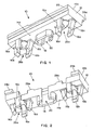
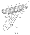
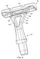
- Figs. 3 to 6 show isometric views of a shaving razor including a standardized razor blade carrier 30, the adapter unit 10 of Figs. 1 and 2, and a razor handle end 50.
- the shaving razor is shown before engagement of the razor blade carrier 30, adapter unit 10, and razor handle end 50.
- the shaving razor is shown with the razor blade carrier 30, adapter unit 10, and handle end 50 engaged together.
- the razor blade carrier 30 is an elongated, generally rectangular structure. The axis of elongation is parallel to the cutting edge of the razor blade or blades contained in the razor blade carrier (blades not shown).
- the razor blade carrier 30 may include any of the blade, guard, and cap features that are well-known in the art (not shown).
- the razor blade carrier 30 includes a bottom base 32 with a resilient lip 44 formed around it. In the center of the base 32, a plateau-like projection 34 extends from the base 32. The plateau-like projection 34 is shaped to fit in between the projections 28a and 28b on the adapter unit 10.
- a pair of support structures 40a and 40b extend from the base 32.
- a plurality of claws 36 are disposed on the lip 44 along one of the longitudinal sides of the razor blade carrier 30.
- a pair of slots 38a and 38b are formed in the support structures 40a and 40b, respectively, on the side of the razor blade carrier 30 opposite from the claws 36.
- the standardized razor blade carrier 30 also includes a pair of cylindrical shafts 42a and 42b formed in the support structures 40a and 40b, respectively, which together define a pivot axis for the razor blade carrier 30 for certain handle designs.
- the cylindrical shafts 42a and 42b are not utilized in the embodiment of Figs. 3 to 6, but will be utilized in a later embodiment.
- the razor handle end 50 is bifurcated into two arms 54a and 54b, which form a V-shape.
- the two arms 54a and 54b are joined at their outer ends by a bridge portion 62.
- Each arm 54a and 54b includes a ball-like projection 56a and 56b, respectively, at its end.
- the bridge portion 62 includes a central, projecting tongue 58, which is T-shaped in cross-section.
- the tabs 24a and 24b of the adapter unit 10 are placed within the slots 38a and 38b, respectively, of the razor blade carrier 30.
- the adapter unit 10 is then pivoted about the longitudinal edge on which the tabs 24a and 24b are located until the elongated projection 22 contacts the claws 36.
- Pressure is then exerted on the adapter unit 10 so that, by camming action of the elongated projection 22 on the claws 36, the claws 36 and the lip 44 are pushed outwardly.
- the claws 36 and the lip 44 return to their original positions, thus locking the adapter unit 10 into the razor blade carrier 30, and thereby forming a razor cartridge.
- the plateau-like projection 34 of the razor blade carrier 30 cooperates with the projections 28a and 28b of the adapter unit 10 to guide and stabilize the adapter unit 10 into position.
- the adapter unit 10 permits the razor cartridge formed thereby to be engaged with the handle end 50 by snapping the ball-like projections 56a and 56b of the handle end 50 into the spherical cavities 26a and 26b formed by the groups of resilient fingers 16a and 16b, respectively, of the adapter unit 10.
- the ball-like projections 56a and 56b and the groups of resilient fingers 16a and 16b form a pair of ball-and-socket joints.
- the tongue 58 of the handle end 50 fits into the socket 18 of the adapter unit 10, with the T-shape of the tongue 58 cooperating with the notch 20 of the socket 18 to guide the razor handle end 50 into the adapter unit 10 in the correct orientation for shaving.
- the socket 18 is slightly wider than the tongue 58 leaving room for play between the tongue 58 and the socket 18 so that the razor cartridge, consisting of the razor blade carrier 30 and the adapter unit 10, may be pivoted on the ball-and-socket joints. The play between the socket 18 and the tongue 58 determines the pivot range of the razor cartridge.
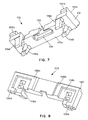
- FIGs. 7 and 8 show isometric views of an adapter unit 110 according to a second preferred embodiment of the present invention.
- the adapter unit 110 includes an elongated, generally rectangular base 112 having a bottom side 114a and a top side 114b.
- the bottom side 114a includes two pairs of resilient fingers 116a and 116b disposed on opposite ends of the longitudinal axis of the base 112. Each pair of resilient fingers 116a and 116b are adapted to receive a cylindrically shaped structure.
- the bottom side 114a also includes a central socket 118.
- the central socket 118 includes a notch 120 running perpendicular to the plane of the bottom side 114a.
- the top side 114b of the adapter unit 110 includes projections extending outwardly from its longitudinal edges. Running along the length of one longitudinal edge, an elongated projection 122 is disposed on the top side 114b. On the opposite longitudinal edge, there are disposed a pair of projecting tabs 124a and 124b. The top side 114b also includes a pair of projections 128a and 128b extending from the top side 114b and running perpendicular to the longitudinal edges of the top side 114b.
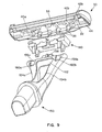
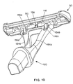
- Figs. 9 and 10 show exploded and assembled isometric views, respectively, of a shaving razor including the standardized razor blade carrier 30 previously described with regard to the embodiment of Figs. 3 to 6, the adapter unit 110 of Figs. 7 and 8, and a razor handle end 150.
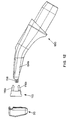
- Figs. 11 and 12 show exploded side views of the same shaving razor.
- the handle end 150 is bifurcated into two arms 154a and 154b, which form a V-shape.
- the two arms 154a and 154b are joined at their outer ends by a bridge portion 162.
- the arms 154a and 154b include recesses 160a and 160b, respectively, at their ends.
- the recesses 160a and 160b include therein cylindrically shaped portions 156a and 156b, respectively.
- the bridge portion 162 includes a central, projecting tongue 158, which is T-shaped in cross-section.
- the projections on the top side 114b of the adapter unit 110 are similar to those of the adapter unit 10 of Figs. 1 to 6.
- the adapter unit 110 is engaged to the standardized razor blade carrier 30 in the same manner as has been described with respect to the adapter unit 10 to thereby form a razor cartridge.
- the handle end 150 is engaged with the adapter unit 110 by snap fitting the rounded portions 156a and 156b into the two pairs of resilient fingers 116a and 116b, respectively.
- the tongue 158 fits into the socket 118, with the T-shape of the tongue 158 cooperating with the notch 120 of the socket 118 to guide the handle end 150 into the adapter unit 110 in the correct orientation for shaving.
- the socket 118 is slightly wider than the tongue 158 leaving room for play between the tongue 158 and the socket 118 so that the razor cartridge may be pivoted about the cylindrically shaped portions 160a and 160b.
- the play between the socket 118 and the tongue 158 determines the pivot range of the razor cartridge formed by the adapter unit 110 and the razor blade carrier 30.
- FIGs. 13 and 14 show isometric views of an adapter unit 210 according to a third preferred embodiment of the present invention.
- the adapter unit 210 includes an elongated, generally rectangular base 212 having a bottom side 214a and a top side 214b.
- the bottom side 214a includes a pair of guiding structures 216a and 216b disposed at opposite ends of the longitudinal axis of the base 212.
- the guiding structures 216a and 216b are generally rectangular structures with central openings 226a and 226b, respectively, and inner walls that taper towards the central openings.
- the bottom side 214a also contains a pair of extending tapered projections 215a and 215b, located between the guiding structures 216a and 216b.
- the top side 214b includes projections that extend outwardly from its longitudinal edges. Extending outwardly along one longitudinal edge of the top side 214b, there are disposed a pair of elongated projections 222a and 222b. On the opposite longitudinal edge, a pair of projecting tabs 224a and 224b are disposed on the top side 214b.
- the top side 214b also includes a pair of projections 228a and 228b extending therefrom and running perpendicular to the longitudinal edges of the top side 214b.
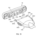
- Fig. 15 shows an isometric view of a shaving razor including the standardized razor blade carrier 30, the adapter unit 210 of Figs. 14 and 15, and a razor handle end 250.
- the adapter unit 210 is shown engaged with the razor blade carrier 30.
- the manner of engagement of the adapter unit 210 with the razor blade carrier 30 is the same as described for the prior two adapter unit embodiments 10 and 110.
- the central openings 226a and 226b are aligned over the openings of the cylindrical shafts 42a and 42b (see Figs. 3 and 4), respectively, on the inside walls of the support structures 40a and 40b of the standardized razor blade carrier 30.
- the razor handle end 250 includes a main casing 255 and, extending from one end of the main casing 255, two arm members 254a and 254b and a central, spring-loaded tongue 258. Extending from the sides of the main casing 255 are two buttons 253a and 253b, which are operatively coupled to the arm members 254a and 254b, in a manner well-known in the art, so as to be able to move the arm members inwardly towards each other.
- the arm members 254a and 254b are normally separated under spring tension from one another by a distance determined by the main casing 255.
- the arm members 254a and 254b contain outwardly extending rounded pins 256a and 256b, respectively, which define a pivot axis for the handle end 250.
- the dimensions of the rounded pins 256a and 256b are such that they fit into the cylindrical shafts 42a and 42b of the standardized razor blade carrier 30, enabling the razor cartridge formed by the standardized razor blade carrier 30 and the adapter unit 210 to pivot with respect to the handle end 250.
- the arm members 254a and 254b are pushed into the guiding structures 216a and 216b of the adapter unit 210.
- the tapered walls of the guiding structures 216a and 216b guide the rounded pins 256a and 256b into the openings of the cylindrical shafts 42a and 42b (see Figs. 3 and 4) of the razor blade carrier 30, respectively.
- the central, spring-loaded tongue 258 cooperates with the bottom side 214a of the adapter unit 210 to bias the razor cartridge to a neutral, rest position.
- the camming action of the central tongue 258 against the bottom side 214a compresses the spring-loaded, central tongue 258 into the main casing 255.
- the compressed, spring-loaded, central tongue 258 acts in reverse against the bottom side 214a to return the razor cartridge to its original, rest position.
- the projections 215a and 215b prevent the central tongue 258 from moving side to side.
- the adapter units of the present invention are composed of plastic and are produced by a two-plate injection molding process.
- the mold has a core pin that is not mechanically activated.
- the plastic material is preferably either polystyrene or ABS.
- the razor blade carriers and handles to be used with the adapter unit of the present invention can be made with any of the materials and processes that are well-known in the art for making such components.
Landscapes
- Life Sciences & Earth Sciences (AREA)
- Forests & Forestry (AREA)
- Engineering & Computer Science (AREA)
- Mechanical Engineering (AREA)
- Packaging Of Annular Or Rod-Shaped Articles, Wearing Apparel, Cassettes, Or The Like (AREA)
- Dry Shavers And Clippers (AREA)
Claims (25)
- Einsatz für einen Rasierapparat zur Verwendung mit einem Rasierapparatgriff (50; 250), der ein Griffbauteil (56a, 56b; 256a, 256b) für den Eingriff aufweist, das sich von einem Ende davon erstreckt, wobei besagter Einsatz für den Rasierapparat umfasst:einen Träger (30) für die Klinge des Rasierapparats, welcher darauf ein Trägerbauteil für den Eingriff aufweist;
undeine Adaptereinheit (10; 210), welche eine erste Seite (14b; 214b) und eine zweite Seite (14a; 214a) aufweist,wobei:besagte erste Seite (14b; 214b) der besagten Adaptereinheit (10; 210) ein erstes Adapterbauteil für den Eingriff aufweist, das so geformt ist, dass es in einen festen Eingriff mit besagtem Trägerbauteil für den Eingriff einschnappt um besagte Adaptereinheit (10; 210) am besagten Träger (30) für die Klinge des Rasierapparats zu befestigen; undbesagte zweite Seite (14a; 214a) der besagten Adaptereinheit (10) ein zweites Adapterbauteil für den Eingriff aufweist, das so geformt ist, dass es mit dem Griffbauteil (56a, 56b; 256a, 256a) für den Eingriff zusammenpasst;wobei das Griffbauteil (56a, 56b; 256a, 256b) für den Eingriff in der Lage ist, an besagten Träger (30) für die Klinge des Rasierapparats über besagte Adaptereinheit (10) angekoppelt zu werden. - Einsatz für einen Rasierapparat nach Anspruch 1, wobei wenigstens das Adapterbauteil für den Eingriff und wenigstens das Trägerbauteil für den Eingriff oder wenigstens das Adapterbauteil für den Eingriff oder wenigstens das Trägerbauteil für den Eingriff unter Widerstand beweglich sind.
- Einsatz für einen Rasierapparat nach einem der vorstehenden Ansprüche, wobei:besagtes Trägerbauteil für den Eingriff eine oder mehrere Klauen (36) umfasst; undbesagtes erstes Adapterbauteil für den Eingriff einen verlängerten Vorsprung umfasst.
- Einsatz für einen Rasierapparat nach Anspruch 1 oder 2, wobei:besagtes Trägerbauteil für den Eingriff einen oder mehrere Schlitze (38a, 38b) umfasst; undbesagtes erstes Adapterbauteil für den Eingriff ein oder mehrere Elemente (tabs) (24a, 24b) umfasst.
- Einsatz für einen Rasierapparat nach einem der vorstehenden Ansprüche, wobei besagtes zweites Adapterbauteil für den Eingriff so geformt ist, dass es drehbar mit dem Griffbauteil (56a, 56b) für den Eingriff zusammenpasst, wobei das Griffbauteil (56a, 56b) für den Eingriff drehbar mit besagtem Träger (30) für die Klinge des Rasierapparats über besagte Adaptereinheit (10) verbunden ist.
- Einsatz für einen Rasierapparat nach Anspruch 5, wobei besagtes zweites Adapterbauteil für den Eingriff wenigstens eine Fassung entsprechend der und geformt für die Aufnahme eines gerundeten Vorsprungs auf dem Griffbauteil (56a, 56b) für den Eingriff umfasst.
- Einsatz für einen Rasierapparat nach Anspruch 6, wobei besagte wenigstens eine Fassung eine Vielzahl von elastischen Fingern (16a, 16b) umfasst.
- Einsatz für einen Rasierapparat nach Anspruch 5, wobei besagtes zweites Adapterbauteil für den Eingriff eine Fassung umfasst entsprechend der und geformt für die Aufnahme eines kugelartigen Vorsprungs auf dem Griffbauteil (56a, 56b) für den Eingriff, wobei, wenn das Griffbauteil (56a, 56b) für den Eingriff und besagtes zweites Adapterbauteil für den Eingriff in einander eingreifen, der kugelartige Vorsprung und besagte Fassung eine drehbare Verbindung zwischen Kugel und Fassung bilden.
- Einsatz für einen Rasierapparat nach Anspruch 8, wobei besagte Fassung eine Vielzahl von nachgiebigen Fingern (16a, 16b) umfasst.
- Einsatz für einen Rasierapparat nach Anspruch 5, wobei besagte Adaptereinheit (10) eine Fassung (18) zum beweglichen Aufnehmen einer zentral hervorstehenden Zunge (58) auf dem Griff (50) aufweist, so dass, wenn der Griff (50) und besagte Adaptereinheit (10) in einander eingreifen, die Zunge (58) und besagte Fassung (18) zusammenwirken, um den drehbaren Bereich des Griffs (50) in Bezug auf besagten Einsatz für den Rasierapparat zu begrenzen.
- Einsatz für einen Rasierapparat nach einem der vorstehenden Ansprüche, wobei besagtes Trägerbauteil für den Eingriff und besagtes Griffbauteil (56a, 56b) für den Eingriff nicht direkt zusammenpassen.
- Einsatz für einen Rasierapparat nach Anspruch 1, wobei besagtes erstes Adapterbauteil für den Eingriff verschließbar mit besagtem Trägerbauteil für den Eingriff zusammenpasst.
- Einsatz für einen Rasierapparat nach einem der vorstehenden Ansprüche, wobei besagter Adapter (10) ein Plastikstück ist.
- Einsatz für einen Rasierapparat nach Anspruch 13, wobei besagte Adaptereinheit (10) ein Stück ist, das durch Spritzgießen hergestellt wird.
- Einsatz für einen Rasierapparat nach Anspruch 1, wobei der Träger (30) für die Rasierklinge, welcher das erste Trägerbauteil für den Eingriff aufweist, auch ein zweites Trägerbauteil für den Eingriff darauf umfasst, wobei besagtes zweites Trägerbauteil für den Eingriff für den drehbaren Eingriff mit dem Griffbauteil (256a, 256b) für den Eingriff geformt ist; und eine Öffnung in besagter zweiten Seite (214a) der besagten Adaptereinheit (210) gebildet wird, um ein Griffbauteil (256a, 256b) für den Eingriff dort hindurch und in drehbaren Eingriff mit besagtem zweiten Trägerbauteil für den Eingriff zu führen.
- Einsatz für einen Rasierapparat nach Anspruch 15, wobei wenigstens das Adapterbauteil für den Eingriff und wenigstens das Trägerbauteil für den Eingriff oder wenigstens das Adapterbauteil für den Eingriff oder wenigstens das Trägerbauteil für den Eingriff elastisch erhältlich sind.
- Einsatz für einen Rasierapparat nach einem der Ansprüche 15 oder 16, wobei:besagtes erstes Trägerbauteil für den Eingriff eine oder mehrere Klauen (36) umfasst;
undbesagtes Adapterbauteil für den Eingriff einen verlängerten Vorsprung (222a, 222b) umfasst. - Einsatz für einen Rasierapparat nach einem der Ansprüche 15 oder 16, wobei:besagtes erstes Trägerbauteil für den Eingriff einen oder mehrere Schlitze (38a, 38b) umfasst;
undbesagtes Adapterbauteil für den Eingriff ein oder mehrere Elemente (tabs) (224a, 224b) umfasst. - Einsatz für einen Rasierapparat nach einem der Ansprüche 15 bis 18, wobei:besagte Adaptereinheit (210) so konfiguriert ist, dass sie besagten Einsatz für einen Rasierapparat adaptiert zur Verwendung mit einem Griff (250), der zwei Armbauteile (254a, 254b) mit sich nach außen erstreckenden Stiften (256a, 256b) aufweist, welche eine Drehachse definieren, um die sich der Griff (250) bezüglich des besagten Trägers (30) für die Klinge des Rasierapparats dreht, und eine zentrale, feder-gespannte Zunge (258) zwischen den Armbauteilen (254a, 254b);wobei besagte Öffnung in besagter zweiter Seite (214a) der besagten Adaptereinheit (210) eine Öffnung für jedes Armbauteil (254a, 254b) des Griffs (250) enthält; und besagte Adaptereinheit (210) eine Bodenseite aufweist, die sich zwischen besagten Öffnungen in besagter zweiter Seite (214a) erstreckt, so dass, wenn der Griff (250) und besagte Adaptereinheit (210) in einander eingreifen, die zentrale, feder-gespannte Zunge (258) mit besagter Bodenseite der besagten Adaptereinheit (210) zusammenwirkt, um besagten Träger (30) für die Klinge des Rasierapparats nach der Drehung bezüglich des Griffs (250) in eine Ruheposition zurückzuführen.
- Einsatz für einen Rasierapparat nach Anspruch 19, wobei besagter Adapter (210) ein Plastikstück ist.
- Einsatz für einen Rasierapparat nach Anspruch 20, wobei besagte Adaptereinheit (210) ein Stück ist, das durch Spritzgießen hergestellt ist.
- Einsatz für einen Rasierapparat nach Anspruch 1, wobei besagte Adaptereinheit (10) weiter umfasst:einen Boden (12), welcher die erste Seite (14b) und die zweite Seite (14a) aufweist.
- Einsatz für einen Rasierapparat nach Anspruch 22, wobei wenigstens das Adapterbauteil für den Eingriff und wenigstens das Trägerbauteil für den Eingriff oder wenigstens das Adapterbauteil für den Eingriff oder wenigstens das Trägerbauteil für den Eingriff unter Widerstand beweglich sind.
- Einsatz für einen Rasierapparat nach einem der Ansprüche 22 oder 23,
wobei ein zweites Adapterbauteil für den Eingriff so gestaltet ist, dass es drehbar mit dem Griffbauteil (56a, 56b) für den Eingriff zusammenpasst. - Einsatz für einen Rasierapparat nach einem der Ansprüche 22 bis 24, wobei eine Öffnung zur Führung des besagten Griffbauteils (56a, 56b) für den Eingriff in drehbaren Eingriff mit einem zweiten Trägerbauteil für den Eingriff gebracht wird, in besagter zweiter Seite (14a) des besagten Bodens (12), wonach es bei Einführung eines Griffbauteils (56a, 56b) für den Eingriff durch besagte Öffnung es ermöglicht wird, das Griffbauteil (56a, 56b) für den Eingriff an den Träger (30) für die Klinge des Rasierapparats anzukoppeln.
Applications Claiming Priority (1)
| Application Number | Priority Date | Filing Date | Title |
|---|---|---|---|
| PCT/US1998/019997 WO2000016951A1 (en) | 1998-09-24 | 1998-09-24 | Adapter unit for a shaving razor |
Publications (3)
| Publication Number | Publication Date |
|---|---|
| EP1115537A1 EP1115537A1 (de) | 2001-07-18 |
| EP1115537A4 EP1115537A4 (de) | 2002-10-09 |
| EP1115537B1 true EP1115537B1 (de) | 2006-07-26 |
Family
ID=22267927
Family Applications (1)
| Application Number | Title | Priority Date | Filing Date |
|---|---|---|---|
| EP98949474A Revoked EP1115537B1 (de) | 1998-09-24 | 1998-09-24 | Adaptereinheit für rasierer |
Country Status (11)
| Country | Link |
|---|---|
| EP (1) | EP1115537B1 (de) |
| JP (1) | JP2002526220A (de) |
| CN (1) | CN1200797C (de) |
| AU (1) | AU763098B2 (de) |
| BR (1) | BR9816028A (de) |
| CA (1) | CA2344872C (de) |
| DE (1) | DE69835377T2 (de) |
| ES (1) | ES2267195T3 (de) |
| HK (1) | HK1048086B (de) |
| MX (1) | MXPA01002969A (de) |
| WO (1) | WO2000016951A1 (de) |
Cited By (2)
| Publication number | Priority date | Publication date | Assignee | Title |
|---|---|---|---|---|
| US11235486B2 (en) | 2010-08-11 | 2022-02-01 | Sphere Usa, Llc | Razor with cutting blade rotatable about multiple axes |
| US11787074B2 (en) | 2019-07-31 | 2023-10-17 | BIC Violex Single Member S.A. | Mechanical assembly of a skin care device, skin care device and process for manufacturing thereof |
Families Citing this family (22)
| Publication number | Priority date | Publication date | Assignee | Title |
|---|---|---|---|---|
| EP1308250A1 (de) * | 2001-11-01 | 2003-05-07 | Warner-Lambert Company | Rasiererbaugruppe mit austauschbarer Kassette |
| US7168173B2 (en) * | 2004-03-11 | 2007-01-30 | The Gillette Company | Shaving system |
| GB2412862A (en) * | 2004-04-08 | 2005-10-12 | Reckitt Benckiser | Depilatory tool with removable head |
| EP1789238B1 (de) | 2004-09-07 | 2008-03-19 | BIC Violex S.A. | Rasierergriff und rasierapparat mit solch einem griff |
| KR100903191B1 (ko) * | 2007-05-31 | 2009-06-17 | 주식회사 도루코 | 면도기 |
| US8205344B2 (en) * | 2008-08-20 | 2012-06-26 | The Gillette Company | Safety razor having pivotable blade unit |
| EP2387489B1 (de) * | 2009-01-05 | 2014-05-14 | The Gillette Company | Andockmechanismus für rasierer und rasierklingeneinheiten |
| US9193080B2 (en) * | 2009-08-03 | 2015-11-24 | The Gillette Company | Shaving blade unit with self-leveling trimmer |
| WO2011042060A1 (en) * | 2009-10-08 | 2011-04-14 | Bic-Violex Sa | Mounting station and method for automatically assembling a razor |
| US8533959B2 (en) * | 2010-10-11 | 2013-09-17 | The Gillette Company | Cartridges and razors with trimming wing |
| US9073226B2 (en) * | 2011-02-09 | 2015-07-07 | The Gillette Company | Pivoting razor |
| US20140116211A1 (en) | 2012-10-25 | 2014-05-01 | Shavelogic, Inc. | Dedicated Attachment Systems for Consumer Products |
| WO2016134439A1 (en) * | 2015-02-27 | 2016-09-01 | Aleem & Company Inc. | A razor assembly |
| CN108290302B (zh) * | 2015-11-20 | 2019-11-15 | 株式会社多乐可 | 剃须刀 |
| EP3378613B1 (de) * | 2015-11-20 | 2021-08-11 | Dorco Co., Ltd. | Rasierergriffanordnung und rasierer damit |
| US10137584B2 (en) * | 2016-05-31 | 2018-11-27 | The Gillette Company Llc | Adapter for a handle and a cartridge of different razor systems |
| US11052558B2 (en) * | 2016-05-31 | 2021-07-06 | The Gillette Company Llc | Adapter for a handle and a cartridge of different razor systems |
| KR101876233B1 (ko) | 2017-09-29 | 2018-07-10 | 주식회사 도루코 | 면도기 카트리지 어셈블리 |
| CN111590646A (zh) * | 2020-06-18 | 2020-08-28 | 广州威的科技有限公司 | 剃刀刀头与剃刀 |
| EP4011573A1 (de) * | 2020-12-14 | 2022-06-15 | BIC Violex Single Member S.A. | Verbinder zum verbinden eines rasierapparatkopfes mit einem rasiererhandgriff |
| KR20240145920A (ko) * | 2023-03-28 | 2024-10-07 | 주식회사 도루코 | 면도기 핸들 |
| EP4570460A1 (de) * | 2023-12-13 | 2025-06-18 | BIC Violex Single Member S.A. | Rasiererverbinder |
Family Cites Families (12)
| Publication number | Priority date | Publication date | Assignee | Title |
|---|---|---|---|---|
| US1200426A (en) * | 1909-05-26 | 1916-10-03 | Carl C King | Safety-razor. |
| US1092367A (en) * | 1910-04-13 | 1914-04-07 | John Everett Knapp | Safety-razor. |
| US3783510A (en) * | 1971-10-22 | 1974-01-08 | Warner Lambert Co | Razor having tandemly mounted blades bonded in a disposable cartridge |
| US3768162A (en) * | 1971-12-13 | 1973-10-30 | Gillette Co | Razor handle |
| US3821851A (en) * | 1972-08-04 | 1974-07-02 | Warner Lambert Co | Razor having inwardly directed single edge blades |
| US4266340A (en) * | 1979-06-11 | 1981-05-12 | Warner-Lambert Company | Razor handle for mounting pivotable razor blade cartridges |
| US4253236A (en) * | 1979-06-19 | 1981-03-03 | The Gillette Company | Razor blade assembly |
| US4288920A (en) * | 1979-11-13 | 1981-09-15 | The Gillette Company | Shaving system with pivotally mounted razor cartridge |
| US4428116A (en) * | 1981-03-02 | 1984-01-31 | Warner-Lambert Company | Support for releasably retaining a blade cartridge |
| US4403414A (en) * | 1981-04-09 | 1983-09-13 | Warner-Lambert Company | Socket device for a pivotal razor |
| DE3635553A1 (de) * | 1986-10-20 | 1988-04-21 | Detlef Koeppen | Rasierapparat |
| GB8710963D0 (en) * | 1987-05-08 | 1987-06-10 | Gillette Co | Safety razors |
-
1998
- 1998-09-24 EP EP98949474A patent/EP1115537B1/de not_active Revoked
- 1998-09-24 WO PCT/US1998/019997 patent/WO2000016951A1/en not_active Ceased
- 1998-09-24 JP JP2000573891A patent/JP2002526220A/ja active Pending
- 1998-09-24 CA CA002344872A patent/CA2344872C/en not_active Expired - Lifetime
- 1998-09-24 AU AU95789/98A patent/AU763098B2/en not_active Expired
- 1998-09-24 ES ES98949474T patent/ES2267195T3/es not_active Expired - Lifetime
- 1998-09-24 HK HK03100229.0A patent/HK1048086B/zh not_active IP Right Cessation
- 1998-09-24 MX MXPA01002969A patent/MXPA01002969A/es active IP Right Grant
- 1998-09-24 BR BR9816028-1A patent/BR9816028A/pt active IP Right Grant
- 1998-09-24 CN CNB988143321A patent/CN1200797C/zh not_active Expired - Lifetime
- 1998-09-24 DE DE69835377T patent/DE69835377T2/de not_active Expired - Lifetime
Cited By (3)
| Publication number | Priority date | Publication date | Assignee | Title |
|---|---|---|---|---|
| US11235486B2 (en) | 2010-08-11 | 2022-02-01 | Sphere Usa, Llc | Razor with cutting blade rotatable about multiple axes |
| US11787074B2 (en) | 2019-07-31 | 2023-10-17 | BIC Violex Single Member S.A. | Mechanical assembly of a skin care device, skin care device and process for manufacturing thereof |
| EP3771530B1 (de) * | 2019-07-31 | 2024-08-28 | BIC Violex Single Member S.A. | Mechanische anordnung einer hautpflegevorrichtung, hautpflegevorrichtung und verfahren zur herstellung davon |
Also Published As
| Publication number | Publication date |
|---|---|
| AU763098B2 (en) | 2003-07-10 |
| CN1359323A (zh) | 2002-07-17 |
| DE69835377T2 (de) | 2007-08-23 |
| HK1048086B (zh) | 2005-12-30 |
| CA2344872A1 (en) | 2000-03-30 |
| CA2344872C (en) | 2008-04-22 |
| BR9816028A (pt) | 2001-05-29 |
| EP1115537A4 (de) | 2002-10-09 |
| HK1048086A1 (en) | 2003-03-21 |
| DE69835377D1 (de) | 2006-09-07 |
| WO2000016951A1 (en) | 2000-03-30 |
| JP2002526220A (ja) | 2002-08-20 |
| ES2267195T3 (es) | 2007-03-01 |
| EP1115537A1 (de) | 2001-07-18 |
| MXPA01002969A (es) | 2003-05-15 |
| CN1200797C (zh) | 2005-05-11 |
| AU9578998A (en) | 2000-04-10 |
Similar Documents
| Publication | Publication Date | Title |
|---|---|---|
| CA2344872C (en) | Adapter unit for a shaving razor | |
| US6880253B1 (en) | Razor with a movable shaving head | |
| RU2263022C2 (ru) | Сменный бритвенный картридж (варианты) | |
| JP3090583B2 (ja) | バックル | |
| AU2001274347A1 (en) | Razor with a movable shaving head | |
| EP0240357B1 (de) | Zapfengelenk | |
| KR100630538B1 (ko) | 면도기 블레이드 시스템 | |
| CN100591492C (zh) | 剃刀手柄和包括该手柄的剃刀 | |
| CA1183339A (en) | Support for releasably retaining a blade cartridge | |
| UA63940C2 (uk) | Змінний картридж лез бритви (варіанти ) , бритва (варіанти) та спосіб приєднання картриджа до ручки | |
| JPH11267374A (ja) | カッターナイフ | |
| WO2015138575A1 (en) | Universal connector and cover for attachment of a windshield wiper blade with multiple types of windshield wiper arms | |
| EP0988135A1 (de) | Klapprasierer | |
| JP2006261138A (ja) | 電気コネクタ | |
| JP4416598B2 (ja) | ひげ剃りかみそりのためのアダプタユニット | |
| JP2008229077A (ja) | カッターナイフ | |
| JPH05342979A (ja) | 暗電流用ヒューズ機構 | |
| JP3541748B2 (ja) | 端子の中継構造 | |
| JP2000067970A (ja) | 挿入力が小さいフラットケ―ブル用コネクタ | |
| JP2979989B2 (ja) | ジョイントコネクタ | |
| JPH0917497A (ja) | コネクタ | |
| JPS5931020Y2 (ja) | 電源プラグ | |
| JP3132508B2 (ja) | 防水コネクタ | |
| JPH0779732B2 (ja) | 爪切りにおける押圧操作てこの支持構造 | |
| JPH09232054A (ja) | 蛍光灯ソケット |
Legal Events
| Date | Code | Title | Description |
|---|---|---|---|
| PUAI | Public reference made under article 153(3) epc to a published international application that has entered the european phase |
Free format text: ORIGINAL CODE: 0009012 |
|
| 17P | Request for examination filed |
Effective date: 20010328 |
|
| AK | Designated contracting states |
Kind code of ref document: A1 Designated state(s): DE ES FR GB |
|
| RIC1 | Information provided on ipc code assigned before grant |
Free format text: 7B 26B 21/08 A, 7B 26B 21/22 B, 7B 26B 21/40 B |
|
| A4 | Supplementary search report drawn up and despatched |
Effective date: 20020827 |
|
| AK | Designated contracting states |
Kind code of ref document: A4 Designated state(s): DE ES FR GB |
|
| 17Q | First examination report despatched |
Effective date: 20030602 |
|
| GRAP | Despatch of communication of intention to grant a patent |
Free format text: ORIGINAL CODE: EPIDOSNIGR1 |
|
| GRAS | Grant fee paid |
Free format text: ORIGINAL CODE: EPIDOSNIGR3 |
|
| GRAA | (expected) grant |
Free format text: ORIGINAL CODE: 0009210 |
|
| AK | Designated contracting states |
Kind code of ref document: B1 Designated state(s): DE ES FR GB |
|
| REG | Reference to a national code |
Ref country code: GB Ref legal event code: FG4D |
|
| REF | Corresponds to: |
Ref document number: 69835377 Country of ref document: DE Date of ref document: 20060907 Kind code of ref document: P |
|
| ET | Fr: translation filed | ||
| REG | Reference to a national code |
Ref country code: ES Ref legal event code: FG2A Ref document number: 2267195 Country of ref document: ES Kind code of ref document: T3 |
|
| PLBI | Opposition filed |
Free format text: ORIGINAL CODE: 0009260 |
|
| PLAX | Notice of opposition and request to file observation + time limit sent |
Free format text: ORIGINAL CODE: EPIDOSNOBS2 |
|
| 26 | Opposition filed |
Opponent name: THE GILLETTE COMPANY Effective date: 20070426 |
|
| PLAF | Information modified related to communication of a notice of opposition and request to file observations + time limit |
Free format text: ORIGINAL CODE: EPIDOSCOBS2 |
|
| PLBB | Reply of patent proprietor to notice(s) of opposition received |
Free format text: ORIGINAL CODE: EPIDOSNOBS3 |
|
| APBM | Appeal reference recorded |
Free format text: ORIGINAL CODE: EPIDOSNREFNO |
|
| APBP | Date of receipt of notice of appeal recorded |
Free format text: ORIGINAL CODE: EPIDOSNNOA2O |
|
| APAH | Appeal reference modified |
Free format text: ORIGINAL CODE: EPIDOSCREFNO |
|
| APBQ | Date of receipt of statement of grounds of appeal recorded |
Free format text: ORIGINAL CODE: EPIDOSNNOA3O |
|
| PGFP | Annual fee paid to national office [announced via postgrant information from national office to epo] |
Ref country code: DE Payment date: 20100929 Year of fee payment: 13 |
|
| RAP2 | Party data changed (patent owner data changed or rights of a patent transferred) |
Owner name: BIC VIOLEX S.A. |
|
| REG | Reference to a national code |
Ref country code: DE Ref legal event code: R103 Ref document number: 69835377 Country of ref document: DE Ref country code: DE Ref legal event code: R064 Ref document number: 69835377 Country of ref document: DE |
|
| APBU | Appeal procedure closed |
Free format text: ORIGINAL CODE: EPIDOSNNOA9O |
|
| PGFP | Annual fee paid to national office [announced via postgrant information from national office to epo] |
Ref country code: FR Payment date: 20111005 Year of fee payment: 14 Ref country code: ES Payment date: 20110926 Year of fee payment: 14 Ref country code: GB Payment date: 20110926 Year of fee payment: 14 |
|
| RDAF | Communication despatched that patent is revoked |
Free format text: ORIGINAL CODE: EPIDOSNREV1 |
|
| RDAG | Patent revoked |
Free format text: ORIGINAL CODE: 0009271 |
|
| STAA | Information on the status of an ep patent application or granted ep patent |
Free format text: STATUS: PATENT REVOKED |
|
| 27W | Patent revoked |
Effective date: 20110915 |
|
| GBPR | Gb: patent revoked under art. 102 of the ep convention designating the uk as contracting state |
Effective date: 20110915 |
|
| REG | Reference to a national code |
Ref country code: DE Ref legal event code: R107 Ref document number: 69835377 Country of ref document: DE Effective date: 20120412 |