EP1115542B1 - Vorrichtung zum verflüssigen von schmelzmassen mit hohem durchsatz und erwärmungsvermögen - Google Patents
Vorrichtung zum verflüssigen von schmelzmassen mit hohem durchsatz und erwärmungsvermögen Download PDFInfo
- Publication number
- EP1115542B1 EP1115542B1 EP99949815A EP99949815A EP1115542B1 EP 1115542 B1 EP1115542 B1 EP 1115542B1 EP 99949815 A EP99949815 A EP 99949815A EP 99949815 A EP99949815 A EP 99949815A EP 1115542 B1 EP1115542 B1 EP 1115542B1
- Authority
- EP
- European Patent Office
- Prior art keywords
- fins
- melting
- grid
- elongated
- reservoir
- Prior art date
- Legal status (The legal status is an assumption and is not a legal conclusion. Google has not performed a legal analysis and makes no representation as to the accuracy of the status listed.)
- Expired - Lifetime
Links
- 238000002844 melting Methods 0.000 title claims abstract description 108
- 230000008018 melting Effects 0.000 title claims abstract description 108
- 239000012815 thermoplastic material Substances 0.000 title claims abstract description 31
- 238000010438 heat treatment Methods 0.000 title claims description 48
- 239000007787 solid Substances 0.000 claims abstract description 22
- 239000004831 Hot glue Substances 0.000 claims description 32
- 238000012546 transfer Methods 0.000 claims description 11
- 238000000034 method Methods 0.000 claims description 8
- 238000007599 discharging Methods 0.000 claims description 2
- 239000002184 metal Substances 0.000 claims 1
- 239000007788 liquid Substances 0.000 abstract description 23
- 239000000853 adhesive Substances 0.000 description 50
- 230000001070 adhesive effect Effects 0.000 description 50
- 238000003491 array Methods 0.000 description 9
- 239000000463 material Substances 0.000 description 8
- 238000011156 evaluation Methods 0.000 description 4
- 239000012530 fluid Substances 0.000 description 4
- XAGFODPZIPBFFR-UHFFFAOYSA-N aluminium Chemical compound [Al] XAGFODPZIPBFFR-UHFFFAOYSA-N 0.000 description 3
- 229910052782 aluminium Inorganic materials 0.000 description 3
- 238000005266 casting Methods 0.000 description 3
- 238000010276 construction Methods 0.000 description 3
- 238000013461 design Methods 0.000 description 3
- 239000000155 melt Substances 0.000 description 3
- 238000012552 review Methods 0.000 description 3
- WYTGDNHDOZPMIW-RCBQFDQVSA-N alstonine Natural products C1=CC2=C3C=CC=CC3=NC2=C2N1C[C@H]1[C@H](C)OC=C(C(=O)OC)[C@H]1C2 WYTGDNHDOZPMIW-RCBQFDQVSA-N 0.000 description 2
- 238000005485 electric heating Methods 0.000 description 2
- 230000001050 lubricating effect Effects 0.000 description 2
- 238000005086 pumping Methods 0.000 description 2
- 125000006850 spacer group Chemical group 0.000 description 2
- 241000237858 Gastropoda Species 0.000 description 1
- 239000004822 Hot adhesive Substances 0.000 description 1
- 230000002411 adverse Effects 0.000 description 1
- 230000003466 anti-cipated effect Effects 0.000 description 1
- 238000013459 approach Methods 0.000 description 1
- 239000011449 brick Substances 0.000 description 1
- 230000015556 catabolic process Effects 0.000 description 1
- 239000011248 coating agent Substances 0.000 description 1
- 238000000576 coating method Methods 0.000 description 1
- 239000004020 conductor Substances 0.000 description 1
- 238000006731 degradation reaction Methods 0.000 description 1
- 230000001627 detrimental effect Effects 0.000 description 1
- 238000005516 engineering process Methods 0.000 description 1
- 230000005484 gravity Effects 0.000 description 1
- 239000012943 hotmelt Substances 0.000 description 1
- 239000011810 insulating material Substances 0.000 description 1
- 230000003993 interaction Effects 0.000 description 1
- 238000012986 modification Methods 0.000 description 1
- 230000004048 modification Effects 0.000 description 1
- 239000008188 pellet Substances 0.000 description 1
- 230000000149 penetrating effect Effects 0.000 description 1
- 230000008569 process Effects 0.000 description 1
- 229920001169 thermoplastic Polymers 0.000 description 1
- 239000004416 thermosoftening plastic Substances 0.000 description 1
- 230000001131 transforming effect Effects 0.000 description 1
- 238000011144 upstream manufacturing Methods 0.000 description 1
Images





Classifications
-
- B—PERFORMING OPERATIONS; TRANSPORTING
- B29—WORKING OF PLASTICS; WORKING OF SUBSTANCES IN A PLASTIC STATE IN GENERAL
- B29B—PREPARATION OR PRETREATMENT OF THE MATERIAL TO BE SHAPED; MAKING GRANULES OR PREFORMS; RECOVERY OF PLASTICS OR OTHER CONSTITUENTS OF WASTE MATERIAL CONTAINING PLASTICS
- B29B13/00—Conditioning or physical treatment of the material to be shaped
- B29B13/02—Conditioning or physical treatment of the material to be shaped by heating
- B29B13/022—Melting the material to be shaped
-
- B—PERFORMING OPERATIONS; TRANSPORTING
- B29—WORKING OF PLASTICS; WORKING OF SUBSTANCES IN A PLASTIC STATE IN GENERAL
- B29K—INDEXING SCHEME ASSOCIATED WITH SUBCLASSES B29B, B29C OR B29D, RELATING TO MOULDING MATERIALS OR TO MATERIALS FOR MOULDS, REINFORCEMENTS, FILLERS OR PREFORMED PARTS, e.g. INSERTS
- B29K2105/00—Condition, form or state of moulded material or of the material to be shaped
- B29K2105/0097—Glues or adhesives, e.g. hot melts or thermofusible adhesives
Definitions
- the present invention relates generally to devices used in connection with melting and dispensing thermoplastic materials and, more particularly, to melting units including grids and reservoirs used for melting and dispensing hot melt adhesive.
- hot melt adhesives are used for various coating and bonding operations such as diaper construction, package forming, automobile parts assembly and various other industrial applications.
- important parameters include the ability to achieve a desired throughput or flow rate of liquid adhesive from the unit and, at the same time, achieve and maintain a relatively precise elevated liquid temperature. This temperature is often referred to as the set point temperature.
- Hopper-type melting units may be used to melt and dispense many forms of thermoplastic adhesives including the forms mentioned above.
- hopper-type dispensers or melting units can first remove the slug from the container and then melt the slug of adhesive as it contacts a heated melting grid mounted near the bottom of the hopper.
- the other forms of adhesive mentioned above may simply be loaded into the hopper.
- a heated reservoir is usually disposed beneath the melting grid to receive the fully or partially melted hot melt adhesive as it passes through the grid. Reservoirs have been designed to maintain the adhesive in a heated liquid state suitable for the application and, for this purpose, various types of fins or other heated surfaces have been provided in the reservoir.
- An outlet of the reservoir typically leads to a pump and heated manifold assembly for pumping the hot melt adhesive to a dispenser appropriate for the application.
- Melting grids have been the primary devices for transforming the adhesive from its initial form into a molten or at least semi-molten state.
- Melting grids may consist of various forms of heated grid members that melt the adhesive on contact. These members are typically elongated fins.
- Melting grids typically include through passages for the melted adhesive.
- Preferred grids take the form of aluminum castings with electrical heating elements cast within the grid structure. This maximizes the service life of the heaters and provides the most uniform temperatures at a reasonable cost.
- Melting grids must be designed to compromise between a number of competing objectives. The primary factors that can be varied to meet these objectives are fin thickness and fin spacing. Fin height is also a factor, but the overall size of the unit and the constraints of casting technology typically limit height.
- Thin fins are preferred to maximize the surface area in contact with the adhesive.
- a minimum thickness is required in the vicinity of the heater to allow for variability of the heater location within the casting and variability in the size of the heater itself.
- a minimum thickness is also required for strength in large units.
- the fins are tapered from a relatively thick section near the heater to a relatively thin tip. However, if the taper is too gradual or the fin is too high, the tip will be much cooler than the heater and this will adversely affect the ability to melt adhesive.
- Widely spaced fins have been preferred to maximize the cutting force on the solid adhesive and minimize the resistance to flow as the adhesive melts. However, if the fins are spaced too widely, solid adhesive will be able to pass through without melting. Also, widely spacing the fins results in fewer overall fins in a given size grid, and thus less surface area for transferring heat to the adhesive.
- melting units have generally provided a significant space within the reservoir for liquid adhesive to accumulate to meet high instantaneous demand. This is a problem because much of the liquid adhesive ends up spaced a significant distance from the nearest heated surface. The liquid adhesive is therefore difficult to heat to a desired temperature. The fact that hot melt adhesive is a poor heat conductor exacerbates this problem. Its relatively high viscosity precludes significant convective heat transfer as well. Also, in start-up conditions, this adhesive is often in a solid state and must be slowly melted and heated to its set point temperature prior to using the unit.
- One way to drive more heat into the adhesive would be to heat the melting elements, such as fins, to a temperature substantially above the desired adhesive temperature.
- the adhesive is likely to char or otherwise degrade under these conditions. This char acts as an insulating layer and degrades the melting performance. It is also likely to break off and clog downstream elements of the system.
- degraded adhesive may not provide the bonding performance required by the application. For these reasons, it is desired that the adhesive closely approach the set point temperature of the reservoir, hoses, and applicator heads, and that strong temperature gradients and associated hot spots be avoided.
- Prior melting units were either relatively small, in which case the residence time in the hoses was sufficient to bring the adhesive up to temperature, or a separate heat exchanger was required between the pump and the hoses.
- the heat exchanger used the pump pressure to overcome the drag caused by the extensive surface area, but this is relatively expensive as it requires a separate heating zone and an additional high pressure component.
- This patent discloses a melting grid having intersecting sets of high and low level grid members and certain other unique features which help achieve a balance between melt rate and flow rate. Advances and improvements in this area are nevertheless desirable.
- thermoplastic material melting unit in which the melting rate, liquid throughput or flow rate, and overall heat transfer are optimized.
- German Utility 85 05 907 discloses a melt unit formed from a series of parallel elements shaped at the ends to define upwardly and downwardly extending fins.
- the upwardly extending fins are crossed by transverse fin elements which form passages with the upwardly extending fins.
- thermoplastic material melting unit including a supply hopper having an interior space for receiving solid thermoplastic material, a liquid reservoir disposed beneath the interior space of the supply hopper and also including an interior space generally defined by side walls and a bottom wall.
- the reservoir includes an outlet for discharging melted thermoplastic material and a plurality of heat exchanging elements disposed within reservoir and extending generally in an upward direction relative to the bottom wall of the reservoir.
- a melting grid is disposed between the supply hopper and the reservoir and includes a plurality of intersecting elongated grid members including a plurality of upwardly extending grid members for contacting and melting the solid thermoplastic material and a plurality of downwardly extending grid members which intermesh with the upwardly extending heat exchanging elements disposed in the liquid reservoir to occupy the interior space of the reservoir.
- At least one heating element is thermally coupled to the melting grid and to the plurality of heat exchanging elements disposed in the reservoir.
- One of the novel aspects of this invention is the intermeshing of the grid members and reservoir heat exchanging elements to greatly increase the surface area available for heat exchange without introducing excessive resistance to the flow of the molten adhesive through the unit. This is possible because the viscosity of the adhesive drops dramatically with increasing temperature. In this regard, solid adhesive will tend to "plug flow" with a thin layer of hot adhesive at low viscosity lubricating the walls of grid members as the adhesive moves through the grid. In the past, extensive surface area in an area where gravity head is the only driving force for fluid flow (i.e., upstream of the pumps) has been avoided to maximize throughput. In other words, extensive surface area in a grid was believed to be detrimental to throughput because of anticipated plugging.
- the initial grid fins may be placed closer together than generally thought feasible in the past while achieving adequate throughput.
- spacing the fins more closely and lengthening the resulting restricted and heated flow path dramatically increased the adhesive temperature leaving the grid.
- the overall throughput penalty for this close spacing was small.
- the adhesive viscosity was much less, allowing even more surface area for heat exchange than in prior art devices. This relatively lower viscosity also allows more opportunity to split and redirect the adhesive so that the "plug flow" can be broken up, and the adhesive can be raised to a uniformly high temperature, despite its very low thermal conductivity.
- thermal boundary layer This is the thin lubricating layer of molten adhesive.
- CFD computational fluid dynamics
- the grid members of the melting grid and the heating elements disposed in the reservoir preferably comprise fins which taper in thickness toward the outer edges thereof.
- the melting grid preferably has both a set of high level grid members and a set of lower level grid members or fins extending upwardly to initially heat, slice and melt the solid thermoplastic material.
- a plurality of sets of heating elements are superimposed or stacked upon one another to provide a combined a melting grid and a heat exchange section of a melting unit. More specifically, serpentine-shaped electrical heating elements are disposed in vertically spaced relation with an upper heating element serving as a primary melting element and lower heating elements serving as secondary melting elements and heat transfer elements to raise the temperature of the melted thermoplastic material to a desired set point within a reservoir.
- the serpentine-shaped heating elements are preferably oriented in vertically spaced relation and with the elements of adjacent grids oriented perpendicularly or transversely to each other. Also, the heating elements in the middle section of a particular grid are more closely spaced together than the heating elements at outer portions thereof.
- grids are formed with a plurality of elongated heating elements carrying a plurality of thin, flat fins. These fins are oriented at an angle relative to the axis of each heating element and serve to transfer heat from the heating elements to the thermoplastic material. These grids are stacked with the fins and heating elements of adjacent grids being oriented perpendicularly or generally transverse to each other. This results in forming multiple flow paths and increased surface area contact with heated surfaces as solid thermoplastic material is melted and heated by the stacked grids.
- Another embodiment of the invention utilizes one or more grids formed by fins having electrical heating elements contained therein and further including generally vertically oriented slots for providing increased flow paths and increased heated surface area. These fins may be tapered and formed into various types of grids and heat exchange devices for disposition within a thermoplastic material melting unit.
- the invention further contemplates methods which may be carried out using the various devices disclosed herein. For example, a method in accordance with this invention may include introducing solid hot melt adhesive onto a plurality of first elongated fins of a melting grid, with the first fins being both heated and tapered to initially heat, slice and at least partially melt the solid hot melt adhesive.
- Hot melt adhesive is then passed into a plurality of elongated channels extending lengthwise along the first elongated fins and further passed into a plurality of second elongated fins which intersect the first elongated fins.
- the second elongated fins are also heated and tapered to again heat and slice the hot melt adhesive in a direction transverse to the first elongated fins.
- the hot melt adhesive is then passed through passages contained between the intersecting first and second elongated fins and, finally, the method involves contacting the hot melt adhesive with a plurality of third elongated and heated fins extending from the melting grid below the first and second elongated fins to transfer additional heat to the hot melt adhesive.
- thermoplastic material melting unit 10 is shown in connection for use with one preferred embodiment of the present invention.
- Various conventional components and accessories have been excluded from Fig. 1, as these are not necessary to an understanding of the present invention.
- melting unit 10 may be used in various capacities for melting different types of thermoplastic material, however, it is especially useful for melting solid hot melt adhesive material.
- a supply hopper 12 is provided for holding a supply of solid hot melt adhesive material which may be introduced by opening a hinged lid 14.
- hot melt adhesive material may be supplied in various forms including those mentioned hereinabove.
- melting unit 10 includes a melting grid 16 and a reservoir 18 for containing melted liquid hot melt adhesive. Melting grid 16 and reservoir 18 are described in more detail below.
- Reservoir 18 includes an upper flange 20 which is fastened to supply hopper 12, for example, with melting grid 16 held therebetween.
- a ring or annular member 24 formed from a thermally insulating material may also be provided, as shown, to thermally isolate upper and lower regions of unit 10. All of these elements are securely fastened by means of fastening bolts 22.
- one or more conventional pumps 26 may be provided and connected to reservoir 18 for pumping liquid hot melt adhesive to various dispensers, for example, in accordance with the application needs.
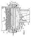
- Fig. 2 illustrates a melting grid 16 in more detail as well as the interaction between melting grid 16 and reservoir 18.
- solid chunks 30 of hot melt adhesive material are contained within supply hopper 12 and rest against melting grid 16. Melting grid 16 heats and melts chunks 30 into a liquid 30a which travels through melting grid 16 into reservoir 18.
- gaskets 32, 34, 36 are provided between supply hopper 12, grid 16, spacer 24 and flange 20 of reservoir 18.
- reservoir 18 includes an interior space 40 defined generally between surrounding side walls 42 and a bottom wall 44. Bottom wall 44 further includes at least one discharge outlet 46 leading to pump 26.
- a bottom surface 48 of reservoir 18 is sloped toward discharge outlet 46 to promote full drainage of liquid hot melt adhesive 30a.
- melting grid 16 further includes a set of fins 60 extending upwardly to contact and melt solid adhesive chunks 30 or other forms of adhesive material.
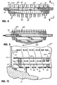
- melting grid 16 is best understood from a review of Figs. 3-5.
- Melting grid 16 is preferably cast from aluminum and, as will be appreciated, is formed to have a significantly increased heated surface area as compared to past grids used for similar purposes.
- fins 60 comprise an upper level or high level of fins extending above a second set of lower level fins 62. Fins 60 and 62 intersect in perpendicular fashion to form an array of through passages 64 as best shown in Fig. 3.
- high level fins 60 preferably each have a serrated leading edge 60a which forms a plurality of apexes or points 60b.
- fins 52 which extend downward relative to fins 60 and 62, may vary in height so that they follow generally the contour of reservoir 18.
- This can include, as shown, outer sets of fins 54, 56 which are of shorter length than inner sets of fins 52 and also include a varying height to the respective fins themselves as shown by trailing edges 52a, 56a in Fig. 5.
- Such features ensure that fins 52, 54, 56, taken together with fins 50 of reservoir 18 (Fig. 2) occupy a substantial portion of interior space 40 associated with reservoir 18.
- heating elements 70, 72, 74 are also inserted are cast within melting grid 16 in a serpentine fashion.
- Associated resistive temperature detectors RTD's, not shown
- RTD's are also inserted into holes (not shown) drilled in grid 16 in a conventional manner for controlling the temperature of grid 16.
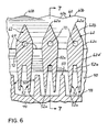
- heating elements 70 are cast within lower level fins 62 as shown in Fig. 6.
- additional heating elements 76, 78, 80 may be embedded into additional downstream portions of melting unit 10, including reservoir 18 and other manifold structure 82 associated with pump 26.
- FIGs. 6 and 7 illustrate the construction of melting grid 16 in more detail.
- lower level fins 62 have lower ends which are extended to form downwardly directed fins 52.
- two fins 52 extend from each lower level fins 62 and taper to trailing edges 52a.
- Fins 52 are situated between pairs of adjacent fins 50 extending upwardly from bottom surface 48 of reservoir 18. This pair of fins 52 traps an air pocket 52a. This air pocket allows for the thermal expansion of the adhesive when the unit is started cold with solidified adhesive in the reservoir area. This concept is further described in U.S. Patent No. 4,771,920, assigned to the assignee of this invention.
- Fins 50 also preferably taper upwardly to leading edges 50a.
- Leading edges 50a are disposed above trailing edges 52a to assure that liquid contained in space 40 is located in close proximity to a heated surface.
- high level fins 60 taper upwardly at a smaller angle than low level fins 62.
- fins 60 have a leading edge 60a with apexes 60b creating a serrated top surface and further having two angled outer surfaces 60c, 60d (Fig. 7). Most preferably, the respective angles of surfaces 60c, 60d relative to vertical are about 4° and about 3°.
- fins 62 have a leading edge 62a and three angled side surfaces 62b, 62c, 62d.
- the respective angle of surfaces 62b, 62c, 62d relative to vertical are about 22°, 4° and 4°.
- the specific angles may vary, however, it is advantageous to have the significant difference in angular relationship between surfaces 60c and 62b.
- the angle of surface 60c may vary between about 3° and about 10°
- the angle of surface 62b may vary between about 10° and about 30°.
- a relatively small throat area 64 is provided for allowing adhesive to flow through grid 16 while becoming well heated in the process.
- throat area 64 is rectangular-shaped and about 5 mm x 18 mm at its smallest area.
- these dimensions may be variable to a range of about 3-8 mm x 10-30 mm for grids constructed similar to grid 16. With the preferred grid 16 and reservoir 18, for example, it may be ensured that all liquid contained in space 40 is located at an approximate maximum distance of between about 3 - 8 mm from the nearest heated surface. This ensures quick heating, uniform heating and minimal degradation of the liquid hot melt adhesive 30a, as well as quicker start-up due to a smaller overall space in which solid hot melt adhesive can accumulate after melting unit 10 is shut down and allowed to cool.
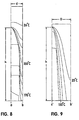
- Figs. 8 and 9 schematically illustrate graphs which represent CFD (computational fluid dynamics) evaluations of two different fin geometries used to melt the same hot melt material.
- Fig. 8 illustrates a CFD model or graphical representation of a fin structure having a height "h" of about 90 mm and represented in a grid where the distance between the center line "a" of the fin and the center line "b" of the throat is a distance "d” which, in this case, is approximately 13.8 mm.
- the line at 150°C represents the approximate location of the thermal boundary layer. This layer extends a significant distance above the bottom of the throat. It will also be noted that the colder layers do not extend a significant distance into the throat area.
- Fig. 8 illustrates a CFD model or graphical representation of a fin structure having a height "h" of about 90 mm and represented in a grid where the distance between the center line "a" of the fin and the center line "b" of the throat is a distance "d” which, in this
- Fig. 9 illustrates a model in which the height "h" of the fin is likewise about 90 mm, but a dramatic difference is shown.
- the distance "D" between the center line a' of the fin and the center line b' of the throat is larger at about 22 mm.
- Fig. 9 represents a fin and throat structure wherein the distance between the center line "b" of the throat and a lower adjacent surface of the fin is approximately 14.3 mm
- Fig. 8 illustrates a fin and throat configuration in which the distance between the center line b' and the lower adjacent surface of the fin is approximately 4.6 mm.
- the larger throat size of Fig. 9 allows the colder temperature layers to drop much farther into the throat area.
- the approximate thermal boundary layer of 150°C is located closely adjacent to the bottom of the fin.
- the downward flow rate of material is about 0.028 cm/sec.
- Figs. 10-12 illustrate one alternative grid and heat exchanger device using bare electric heating element arrays 102, 104, 106, 108, 110 formed, for example, in a serpentine fashion as shown.
- adjacent elements are oriented perpendicularly or at least transverse to one another. As viewed in Fig. 11, this ensures that contact between adhesive flowing through device 100 and heating element arrays 102-110 is maximized.
- a net or grid of bare heating elements is formed to maximize heat transfer to the melting and melted adhesive.
- inner portions of each heating element arrays 102-110 may be more closely spaced than outer portions thereof.
- portions 102a are more closely spaced than outer portions 102b. This may equalize flow in the center of each array 102-110 in relation to the outer portions of each array 102-110.
- the watt density may be less in the center than in the outer portions.
- heating element array 102 may be used as an initial melter and positioned at the lower end of a hopper 12' for example, mounted on a suitable support 112. This array 102 then acts as a gate to allow adhesive into the lower heat exchanger section formed by heating element arrays 104-110. In this manner, heating element array 102 can quickly melt solid adhesive and this melted adhesive will fall into the heat exchanger section formed by heating element arrays 104-110. These arrays 104-110 may then act to raise the liquid adhesive to the desired set point temperature.
- Heating element arrays 104, 110 may be spaced apart by suitable spacers 114 and a plurality of resistive temperature detectors (RTDs) 116 and 118 may be placed in contact with heating element arrays 104-110 as shown to indicate the temperature thereof to a conventional control.
- Arrays 104-110 may be mounted on an upper surface or mounting portion 120 of a reservoir 18' connected at a lower end of supply hopper 12'.
- Reservoir 18' may include a suitable electrical heating devices and fins (not shown) as well as sloped drainage surfaces and one or more discharge outlets as previously described in connection with the first embodiment.
- Device 100 may have various advantages including a high relative melt rate, a low overall mass for quick warm-up and cool-down, accurate control of fluid temperature, high efficiency due to direct contact between the adhesive and the heating elements and a relatively low average distance between the adhesive and the heated surfaces.
- Figs. 13-15 illustrate yet another embodiment generally incorporating concepts of the present invention.
- This embodiment is similar to the embodiment described immediately above, except that a multilayered finned grid 130 is formed by a stacked arrangement of finned grids 132, 134, 136.
- the respective grids 132, 134, 136 are formed by electrical heating elements 132a, 134a, 136a holding a respective plurality of thin, angled fins 132b, 134b, 136b.
- Fins 132b, 134b, 136b are oriented perpendicular, or at least transverse to adjacent sets thereof as shown in Figs. 13 and 15.
- the angle of fins 132b, 134b, 136b increases the surface area and residence time of adhesive in device 130.
- Heating elements 132a, 134a, 136a may be cast with fins 132b, 134b, 136b.
- Device 130 may be used within a hot melt adhesive melting unit such as generally described above and in conjunction with a reservoir (not shown) which may have additional heating elements and fin arrangements. Again, device 130 may be produced with a low overall mass for quick warm-up and may allow for precise control of liquid temperature or set point temperature. Finally, varying the fin angles effectively mixes the hot melt adhesive or thermoplastic material as it flows through the device to ensure more uniform liquid temperature.
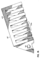
- Fig. 16 illustrates a perspective view of one alterative fin configuration useful in melting units, such as those of the present invention.
- This particular configuration is designed to provide a high melt rate via a high concentration of fins with a provision to allow easy removal of liquid adhesive.
- a slotted fin configuration may be used for increasing both heat transfer and liquid adhesive flow.
- a tapered fin 150 may include an upper leading edge 150a and a series of generally vertically oriented slots 150b.
- fin 150 may be cast from aluminum and may include a resistive-type electric heating element 152 therein.
- Slots 150b both increase the surface area of fin 150 to increase heat transfer and, at the same time, provide multiple liquid flow paths past fin 150.
- fin 150 may be tapered in upward and/or downward fashion, such as disclosed with respect to the first embodiment of this invention.
- the grid members and/or heat exchanging elements of the invention in its many forms may include the slotted fin design.
Landscapes
- Physics & Mathematics (AREA)
- Thermal Sciences (AREA)
- Engineering & Computer Science (AREA)
- Mechanical Engineering (AREA)
- Adhesives Or Adhesive Processes (AREA)
- Coating Apparatus (AREA)
- Processing And Handling Of Plastics And Other Materials For Molding In General (AREA)
- Heating, Cooling, Or Curing Plastics Or The Like In General (AREA)
Claims (21)
- Vorrichtung (10) zum Schmelzen von thermoplastischem Material, umfassend ein Schmelzgitter (16, 130, 160), wobei das Schmelzgitter mehrere, sich abwärts erstreckende längliche Gitterelemente (52, 54, 56) besitzt, einen Vorratsbehälter (18) zum Aufnehmen des schmelzflüssigen thermoplastischen Materiales vom Schmelzgitter, und mindestens ein mit den länglichen Gitterelementen (52, 54, 56) thermisch verbundenes Heizelement (70, 72, 74, 76, 78, 132a, 134a, 136a), dadurch gekennzeichnet, dass die Vorrichtung mehrere, in dem Vorratsbehälter (18) angeordnete und sich in Aufwärtsrichtung erstreckende, längliche Wärmeübertragungselemente (50) umfasst; dass die länglichen Gitterelemente (52, 54, 56) mit den sich aufwärts erstreckenden Wärmeübertragungselementen (50) ineinander greifen, und dass das mindestens eine Heizelement (70, 72, 74, 76, 78, 132a, 134a, 136a, 170, 172, 174) mit den mehreren Wärmeübertragungselementen (50) thermisch verbunden ist.
- Vorrichtung gemäß Anspruch 1, außerdem umfassend einen Beschickungsbehälter (12) zum Aufnehmen des thermoplastischen Materiales und Zuführen des thermoplastischen Materiales zum Schmelzgitter (16, 130, 160).
- Schmelzvorrichtung gemäß Anspruch 2, bei der die Wärmeübertragungselemente und die sich abwärts erstreckenden Gitterelemente außerdem Rippen (50, 52, 54, 56) umfassen.
- Schmelzvorrichtung gemäß Anspruch 3, bei der die Rippen (50, 52, 54, 56) Außenkanten besitzen und zu den Außenkanten hin dünner werden.
- Schmelzvorrichtung nach einem der vorhergehenden Ansprüche, bei der der Vorratsbehälter (18) außerdem einen Boden (44) umfasst, der eine Neigung zur Unterstützung des Ablaufs des schmelzflüssigen thermoplastischen Materiales besitzt, und die mehreren sich abwärts erstreckenden Gitterelemente (52,54, 56) unterschiedliche Höhen entsprechend der Neigung der Bodenwand haben.
- Schmelzvorrichtung gemäß einem der vorhergehenden Ansprüche, bei der die Bodenwand (44) des Vorratsbehälters (18) in mindestens zwei Richtungen geneigt ist und die Gitterelemente (52, 54, 56) in beiden Richtungen jeweils unterschiedliche Höhen haben, so dass sie in einer Art und Weise entsprechend der Bodenwand des Vorratsbehälters (18) abgeschrägt sind.
- Schmelzvorrichtung gemäß einem der vorhergehenden Ansprüche, bei der die Schmelzvorrichtung (10) aus Metall gegossen ist und das mindestens eine Heizelement (70, 72, 74, 76, 78, 132a, 134a, 136a) innerhalb des Schmelzgitters (16, 130, 160) angeordnet ist.
- Schmelzvorrichtung gemäß einem der Ansprüche 1 bis 6, bei der separate Heizelemente (70, 72, 74, 76, 78, 132a, 134a, 136a) mit den länglichen Gitterelementen des Schmelzgitters (16, 130, 160) und den Wärmeübertragungselementen (50) des Vorratsbehälters (18) thermisch verbunden sind.
- Schmelzvorrichtung gemäß einem der vorhergehenden Ansprüche, bei dem die länglichen Wärmeübertragungselemente (50) sich quer zur ihren Längsausdehnungen erstreckende Schlitze besitzen.
- Schmelzvorrichtung gemäß Anspruch 9, bei der die länglichen Gitterelemente (52, 54, 56) sich quer zu ihren Längsausdehnungen erstreckende Schlitze besitzen.
- Schmelzvorrichtung gemäß einem der Ansprüche 1 bis 9, bei der mindestens einige der länglichen Gitterelemente (52, 54, 56) sich quer zu ihren Längsausdehnungen erstreckende Schlitze besitzen.
- Vorrichtung (10) zum Verflüssigen von thermoplastischem Material, umfassend einen Beschickungsbehälter (12) zum Aufnehmen festen thermoplastischen Materiales, einen mit dem Beschickungsbehälter (12) kommunizierenden Vorratsbehälter (18) zum Austragen des schmelzflüssigen thermoplastischen Materiales, ein mit dem Beschickungsbehälter (12) verbundenes Schmelzgitter (16) zum Hindurchführen des schmelzflüssigen thermoplastischen Materiales zum Vorratsbehälter, wobei das Schmelzgitter (16) erste, zweite und dritte Sätze länglicher Rippen (60, 62, 52, 54, 56) umfasst, sich mindestens die ersten und zweiten Sätze länglicher Rippen (60, 62) kreuzen, so dass eine Gitterstruktur gebildet wird, die Durchgänge (64) besitzt, der erste Rippensatz durch eine Vielzahl hoch liegender Rippen (60) und der zweite Rippensatz durch eine Vielzahl tief liegender Rippen (62) gebildet wird, wobei die hoch und tief liegenden Rippen (60, 62) Vorderkanten (60a, 62a) besitzen, und die Vorderkanten der hoch liegenden Rippen über den Vorderkanten der tief liegenden Rippen angeordnet sind, und der dritte Satz länglicher Rippen (52, 54, 56) entsprechende Hinterkanten (52a, 54a, 56a) besitzt, die unterhalb der ersten und zweiten Sätze länglicher Rippen (60, 62) angeordnet sind, und eine erste Heizvorrichtung (70, 72, 74), die mit dem ersten, zweiten und dritten Rippensatz thermisch verbunden ist, dadurch gekennzeichnet, dass die Vorrichtung außerdem einen vierten Rippensatz (50) umfasst, der im Vorratsbehälter (18) angeordnet ist und sich in Aufwärtsrichtung erstreckt, wobei Rippen (50) im vierten Rippensatz mit Rippen (52, 54, 56) im dritten Rippensatz ineinander greifen und eine zweite Heizvorrichtung (76, 78) mit dem vierten Rippensatz (50) thermisch verbunden ist.
- Schmelzvorrichtung gemäß Anspruch 13, bei der die Heizelemente (70, 72, 74) in den tief liegenden Rippen (62) aufgenommen sind und der erste und zweite Rippensatz (60, 62) miteinander in thermischem Kontakt steht, so dass Wärme von den tief liegenden Rippen zu den hoch liegenden Rippen übertragen wird.
- Schmelzvorrichtung gemäß Anspruch 13, bei der gegenüberliegende Seitenflächen der hoch liegenden Rippen (60) sich aufwärts zueinander in einem kleineren Winkel in Bezug auf die Vertikale verjüngen als gegenüberliegende Seitenflächen der tief liegenden Rippen (62)
- Schmelzvorrichtung gemäß einem der Ansprüche 12 bis 14, bei der die Vorderkanten (60a) der hoch liegenden Rippen (60) geriffelt sind, um ihre Schneidund Wärmekapazität zu erhöhen.
- Schmelzvorrichtung gemäß einem der Ansprüche 12 bis 15, bei der die tief liegenden Rippen (62) im wesentlichen parallel zueinander und im wesentlichen parallel zum vierten Rippensatz (50) sind.
- Schmelzvorrichtung gemäß einem der Ansprüche 12 bis 16, bei der die tief liegenden Rippen (62) im wesentlichen senkrecht zu den hoch liegenden Rippen (60) und im wesentlichen parallel zum dritten Rippensatz (52) ausgerichtet sind.
- Schmelzvorrichtung nach einem der Ansprüche 12 bis 17, bei der gegenüberliegende Seitenflächen der hoch liegenden Rippen (60) aufwärts in einem Winkel zwischen ungefähr 3° und ungefähr 10° in Bezug auf die Senkrechte zusammenlaufen.
- Schmelzvorrichtung gemäß Anspruch 18, bei der gegenüberliegenden Seitenflächen der tief liegenden Rippen (62) aufwärts in einem Winkel zwischen ungefähr 10° und ungefähr 30° in Bezug auf die Senkrechte zusammenlaufen.
- Schmelzvorrichtung nach einem der Ansprüche 12 bis 19, bei der die Rippen (52, 54, 56) im dritten Rippensatz sich zu ihren Hinterkanten (52a, 54a, 56a) hin verjüngen.
- Verfahren zum Verflüssigen fester Schmelzkleber, umfassend das Erwärmen und Schneiden des festen Schmelzklebers mit einem ersten Satz länglicher Rippen (60) zum mindestens teilweisen Verflüssigen des festen Schmelzklebers, Erwärmen und Schneiden des Schmelzklebers mit einem zweiten Satz länglicher Rippen (62), der sich quer zum ersten Satz länglicher Rippen (60) erstreckt, wobei mindestens der erste Satz und der zweite Satz länglicher Rippen ineinander greifen, so dass eine über einem Vorratsbehälter liegende Schmelzgitterstruktur gebildet wird, und Erwärmen des Schmelzklebers mit einem dritten Satz länglicher Rippen (52, 54, 56), der sich unterhalb des ersten und zweiten Satzes länglicher Rippen (60, 62) abwärts erstreckt, dadurch gekennzeichnet, dass das Verfahren das Erwärmen des Schmelzklebers mit einem vierten Satz länglicher Rippen (50) umfasst, der im Vorratsbehälter angeordnet ist und sich aufwärts erstreckt und mit dem dritten Satz länglicher Rippen (52) ineinander greift.
Applications Claiming Priority (3)
| Application Number | Priority Date | Filing Date | Title |
|---|---|---|---|
| US159448 | 1993-11-30 | ||
| US09/159,448 US6175101B1 (en) | 1998-09-24 | 1998-09-24 | Thermoplastic material melting unit having high throughput and heating capacity |
| PCT/US1999/022093 WO2000016954A1 (en) | 1998-09-24 | 1999-09-23 | Thermoplastic material melting unit having high throughput and heating capacity |
Publications (2)
| Publication Number | Publication Date |
|---|---|
| EP1115542A1 EP1115542A1 (de) | 2001-07-18 |
| EP1115542B1 true EP1115542B1 (de) | 2002-11-27 |
Family
ID=22572653
Family Applications (1)
| Application Number | Title | Priority Date | Filing Date |
|---|---|---|---|
| EP99949815A Expired - Lifetime EP1115542B1 (de) | 1998-09-24 | 1999-09-23 | Vorrichtung zum verflüssigen von schmelzmassen mit hohem durchsatz und erwärmungsvermögen |
Country Status (6)
| Country | Link |
|---|---|
| US (1) | US6175101B1 (de) |
| EP (1) | EP1115542B1 (de) |
| JP (1) | JP2002526292A (de) |
| AU (1) | AU6260699A (de) |
| DE (1) | DE69904215T2 (de) |
| WO (1) | WO2000016954A1 (de) |
Cited By (2)
| Publication number | Priority date | Publication date | Assignee | Title |
|---|---|---|---|---|
| DE202011004910U1 (de) | 2011-04-06 | 2012-07-09 | Brandt Kantentechnik Gmbh | Haftmittelzufuhrvorrichtung |
| EP3225316A1 (de) | 2016-04-01 | 2017-10-04 | Robatech AG | Vorrichtung zum schmelzen von klebstoff |
Families Citing this family (35)
| Publication number | Priority date | Publication date | Assignee | Title |
|---|---|---|---|---|
| US6740851B2 (en) | 2002-09-27 | 2004-05-25 | Nordson Corporation | Quick connect hot melt unit |
| US6499629B1 (en) * | 1999-05-28 | 2002-12-31 | Nordson Corporation | Dispensing apparatus for viscous liquids |
| DE10042478B4 (de) * | 2000-08-29 | 2007-03-15 | Bühler AG | Verfahren zum Aufschmelzen von Polymergranulat sowie Abschmelzelement |
| US20050093403A1 (en) * | 2003-10-31 | 2005-05-05 | Nordson Corporation | Support and storage system for an adhesive dispensing unit |
| US7400670B2 (en) | 2004-01-28 | 2008-07-15 | Rambus, Inc. | Periodic calibration for communication channels by drift tracking |
| US7626143B2 (en) * | 2005-02-17 | 2009-12-01 | Scott Richard Miller | Apparatus and method for processing hot melt adhesives |
| US7728260B2 (en) * | 2005-06-07 | 2010-06-01 | Johnson Steven X | Warm window system |
| ES2378331T3 (es) | 2006-01-17 | 2012-04-11 | Nordson Corporation | Aparato y procedimiento para la fusión y la distribución de material termoplástico |
| ES2524923T3 (es) | 2007-01-29 | 2014-12-15 | Nordson Corporation | Aparato para la distribución de material fusible |
| US8096648B2 (en) * | 2009-01-30 | 2012-01-17 | Xerox Corporation | Ink melt device with solid state retention and molten ink pass-through |
| US8136933B2 (en) * | 2009-01-30 | 2012-03-20 | Xerox Corporation | Solid ink melt tub with corrugated melt region and offset outlet |
| US8240829B2 (en) * | 2009-12-15 | 2012-08-14 | Xerox Corporation | Solid ink melter assembly |
| US20110203653A1 (en) * | 2010-02-23 | 2011-08-25 | Johnson Steven X | Photovoltaic buss bar system |
| USD647380S1 (en) | 2010-06-29 | 2011-10-25 | Nordson Corporation | Cover for an adhesive dispensing gun |
| US8210398B2 (en) | 2010-06-29 | 2012-07-03 | Nordson Corporation | Thermally insulated applicator |
| CN103998200A (zh) * | 2011-09-14 | 2014-08-20 | 卡维斯特公司 | 成型装置 |
| ES2914627T3 (es) * | 2011-10-27 | 2022-06-14 | Graco Minnesota Inc | Fundidor |
| KR20140099883A (ko) * | 2011-11-07 | 2014-08-13 | 그라코 미네소타 인크. | 용융 시스템 |
| DE102012206104A1 (de) * | 2012-04-13 | 2013-10-17 | Hauni Maschinenbau Ag | Heißleimschmelzvorrichtung |
| US9169088B2 (en) | 2012-09-20 | 2015-10-27 | Nordson Corporation | Adhesive dispensing device having optimized cyclonic separator unit |
| US10099242B2 (en) | 2012-09-20 | 2018-10-16 | Nordson Corporation | Adhesive melter having pump mounted into heated housing |
| US9304028B2 (en) | 2012-09-20 | 2016-04-05 | Nordson Corporation | Adhesive dispensing device having optimized reservoir and capacitive level sensor |
| US9120115B2 (en) | 2012-10-25 | 2015-09-01 | Nordson Corporation | Dispensing systems and methods for monitoring actuation signals for diagnostics |
| US9200741B2 (en) | 2012-10-25 | 2015-12-01 | Nordson Corporation | Adhesive dispensing system and method using smart melt heater control |
| USD678374S1 (en) | 2012-10-26 | 2013-03-19 | Nordson Corporation | Wall mounted adhesive melter |
| US9243626B2 (en) | 2012-11-19 | 2016-01-26 | Nordson Corporation | Adhesive dispensing system and method including a pump with integrated diagnostics |
| US9574714B2 (en) | 2013-07-29 | 2017-02-21 | Nordson Corporation | Adhesive melter and method having predictive maintenance for exhaust air filter |
| AT515952B1 (de) | 2014-06-20 | 2016-08-15 | Engel Austria Gmbh | Aufschmelz- und Injektionsvorrichtung für Kunststoffe |
| AU2015287578B2 (en) * | 2014-07-10 | 2019-09-19 | Waterblasting, Llc | Device for melting and applying thermoplastic material to surfaces |
| WO2016183346A1 (en) * | 2015-05-12 | 2016-11-17 | Moldman Systems Llc | Hot melt material processor utilizing insulating non-stick upper section |
| CN105196501A (zh) * | 2015-05-12 | 2015-12-30 | 铸模工艺系统有限公司 | 使用绝缘的不粘的上区段的热熔材料处理器 |
| US10486185B2 (en) * | 2015-11-20 | 2019-11-26 | Illinois Tool Works Inc. | Positioning device in a melting unit of a hot melt adhesive system |
| WO2019089359A1 (en) * | 2017-10-31 | 2019-05-09 | Nordson Corporation | Melting system having a melt grid with support structures |
| WO2019089370A1 (en) * | 2017-10-31 | 2019-05-09 | Nordson Corporation | Melting system including flow guide members |
| EP4209320A1 (de) * | 2017-10-31 | 2023-07-12 | Nordson Corporation | Schmelzsystem enthaltend eine schmelzeinheit mit einem seiteneinfülltrichter |
Family Cites Families (9)
| Publication number | Priority date | Publication date | Assignee | Title |
|---|---|---|---|---|
| GB1223674A (en) | 1967-02-07 | 1971-03-03 | Ernest Horace Priest | Apparatus and method for melting a solid |
| US3531023A (en) * | 1968-04-30 | 1970-09-29 | Mercer Corp | Process and apparatus for melting and dispensing thermoplastic material |
| FR2221253A1 (en) | 1973-03-12 | 1974-10-11 | Steinmeyer Maschinenbau Elektr | Melting bath for synthetic thermoplastic adhesives - with insulated electrical resistances threaded through waveform metal tubes |
| US4667850A (en) * | 1985-10-28 | 1987-05-26 | Nordson Corporation | Thermoplastic grid melter |
| US4771920A (en) | 1985-10-29 | 1988-09-20 | Nordson Corporation | Thermoplastic grid melter |
| US4850425A (en) * | 1987-04-06 | 1989-07-25 | Anderson Steven R | Apparatus for preparing adhesives for application |
| DE8805907U1 (de) | 1988-05-04 | 1989-03-30 | Planatolwerk Willy Hesselmann Chemische- und Maschinenfabrik für Klebetechnik GmbH & Co KG, 8201 Rohrdorf | Vorrichtung zum Verflüssigen von Schmelzmassen |
| JP2983313B2 (ja) * | 1991-02-13 | 1999-11-29 | 松下工業株式会社 | 熱可塑性合成樹脂の熱溶解溶融装置 |
| US5657904A (en) | 1995-10-17 | 1997-08-19 | Nordson Corporation | High flow melting grid and melter unit |
-
1998
- 1998-09-24 US US09/159,448 patent/US6175101B1/en not_active Expired - Fee Related
-
1999
- 1999-09-23 DE DE69904215T patent/DE69904215T2/de not_active Expired - Fee Related
- 1999-09-23 WO PCT/US1999/022093 patent/WO2000016954A1/en not_active Ceased
- 1999-09-23 AU AU62606/99A patent/AU6260699A/en not_active Abandoned
- 1999-09-23 JP JP2000573894A patent/JP2002526292A/ja active Pending
- 1999-09-23 EP EP99949815A patent/EP1115542B1/de not_active Expired - Lifetime
Cited By (4)
| Publication number | Priority date | Publication date | Assignee | Title |
|---|---|---|---|---|
| DE202011004910U1 (de) | 2011-04-06 | 2012-07-09 | Brandt Kantentechnik Gmbh | Haftmittelzufuhrvorrichtung |
| EP2508320A1 (de) | 2011-04-06 | 2012-10-10 | Brandt Kantentechnik GmbH | Haftmittelzufuhrvorrichtung |
| EP3225316A1 (de) | 2016-04-01 | 2017-10-04 | Robatech AG | Vorrichtung zum schmelzen von klebstoff |
| US10412786B2 (en) | 2016-04-01 | 2019-09-10 | Robatech Ag | Device for melting adhesive |
Also Published As
| Publication number | Publication date |
|---|---|
| EP1115542A1 (de) | 2001-07-18 |
| DE69904215D1 (de) | 2003-01-09 |
| WO2000016954A1 (en) | 2000-03-30 |
| US6175101B1 (en) | 2001-01-16 |
| AU6260699A (en) | 2000-04-10 |
| JP2002526292A (ja) | 2002-08-20 |
| DE69904215T2 (de) | 2003-07-24 |
Similar Documents
| Publication | Publication Date | Title |
|---|---|---|
| US6175101B1 (en) | Thermoplastic material melting unit having high throughput and heating capacity | |
| EP0074839B1 (de) | Vorrichtung zum Schmelzen und Verteilen von thermoplastischem Material | |
| US5657904A (en) | High flow melting grid and melter unit | |
| EP0176074B1 (de) | Wärmetauscherelement aus Keramik | |
| US4934916A (en) | Perforated plate for the underwater granulating of plastic strands | |
| JPH09187711A (ja) | 溶融熱可塑性材料を供給するための構成変更可能な装置 | |
| CA2684030A1 (en) | Heat transfer unit for heating systems and surfaces and railway point heater | |
| JPH0767548B2 (ja) | 熱可塑性物用グリツド溶融器 | |
| US20090087355A1 (en) | Variable plate heat exchangers | |
| AU755036B2 (en) | High output device for liquifying or reducing the viscosity of materials | |
| EP0743151B1 (de) | Schmelzvorrichtung | |
| CN100587239C (zh) | 容器结构 | |
| US11525618B2 (en) | Enhanced heat exchanger performance under frosting conditions | |
| CA2325119A1 (en) | Latent heat storage unit | |
| US7015427B1 (en) | Apparatus and method for melting and supplying thermoplastic material to a dispenser | |
| US4474029A (en) | Hot gas defrost pan and system | |
| EP0971859B1 (de) | Kühllamelle für eine vorrichtung zum herstellen von fasern | |
| US8348404B2 (en) | Method and system for melter tank airflow management | |
| US7082985B2 (en) | Moulding apparatus | |
| JPH11165112A (ja) | ホットメルト接着剤溶融装置 | |
| JPH10288436A (ja) | 氷蓄熱システムにおけるスタティック型製氷装置 | |
| US20040221608A1 (en) | Combined ice/beverage dispenser and icemaker with heated drip tray | |
| CN220681698U (zh) | 一种用于连续供胶系统的加热盘及含有其的供胶装置 | |
| KR20230045017A (ko) | 상변화물질의 동결, 전달, 보관 및 활용을 위한 열교환 시스템 및 해당 시스템의 열 에너지 저장 시스템에의 적용 | |
| JPH0914702A (ja) | 氷蓄熱ユニット装置及びその運転方法 |
Legal Events
| Date | Code | Title | Description |
|---|---|---|---|
| PUAI | Public reference made under article 153(3) epc to a published international application that has entered the european phase |
Free format text: ORIGINAL CODE: 0009012 |
|
| 17P | Request for examination filed |
Effective date: 20010302 |
|
| AK | Designated contracting states |
Kind code of ref document: A1 Designated state(s): AT BE CH CY DE DK ES FI FR GB GR IE IT LI LU MC NL PT SE |
|
| GRAG | Despatch of communication of intention to grant |
Free format text: ORIGINAL CODE: EPIDOS AGRA |
|
| 17Q | First examination report despatched |
Effective date: 20020215 |
|
| GRAG | Despatch of communication of intention to grant |
Free format text: ORIGINAL CODE: EPIDOS AGRA |
|
| GRAH | Despatch of communication of intention to grant a patent |
Free format text: ORIGINAL CODE: EPIDOS IGRA |
|
| GRAH | Despatch of communication of intention to grant a patent |
Free format text: ORIGINAL CODE: EPIDOS IGRA |
|
| GRAA | (expected) grant |
Free format text: ORIGINAL CODE: 0009210 |
|
| AK | Designated contracting states |
Kind code of ref document: B1 Designated state(s): DE FR SE |
|
| PG25 | Lapsed in a contracting state [announced via postgrant information from national office to epo] |
Ref country code: FR Free format text: LAPSE BECAUSE OF FAILURE TO SUBMIT A TRANSLATION OF THE DESCRIPTION OR TO PAY THE FEE WITHIN THE PRESCRIBED TIME-LIMIT Effective date: 20021127 |
|
| REG | Reference to a national code |
Ref country code: IE Ref legal event code: FG4D |
|
| REF | Corresponds to: |
Ref document number: 69904215 Country of ref document: DE Date of ref document: 20030109 |
|
| EN | Fr: translation not filed | ||
| PLBE | No opposition filed within time limit |
Free format text: ORIGINAL CODE: 0009261 |
|
| STAA | Information on the status of an ep patent application or granted ep patent |
Free format text: STATUS: NO OPPOSITION FILED WITHIN TIME LIMIT |
|
| 26N | No opposition filed |
Effective date: 20030828 |
|
| REG | Reference to a national code |
Ref country code: IE Ref legal event code: MM4A |
|
| PGFP | Annual fee paid to national office [announced via postgrant information from national office to epo] |
Ref country code: SE Payment date: 20040922 Year of fee payment: 6 Ref country code: DE Payment date: 20040922 Year of fee payment: 6 |
|
| PG25 | Lapsed in a contracting state [announced via postgrant information from national office to epo] |
Ref country code: SE Free format text: LAPSE BECAUSE OF NON-PAYMENT OF DUE FEES Effective date: 20050924 |
|
| PG25 | Lapsed in a contracting state [announced via postgrant information from national office to epo] |
Ref country code: DE Free format text: LAPSE BECAUSE OF NON-PAYMENT OF DUE FEES Effective date: 20060401 |
|
| EUG | Se: european patent has lapsed |