EP1115813B1 - method and computer program for gasification control - Google Patents
method and computer program for gasification control Download PDFInfo
- Publication number
- EP1115813B1 EP1115813B1 EP99944034A EP99944034A EP1115813B1 EP 1115813 B1 EP1115813 B1 EP 1115813B1 EP 99944034 A EP99944034 A EP 99944034A EP 99944034 A EP99944034 A EP 99944034A EP 1115813 B1 EP1115813 B1 EP 1115813B1
- Authority
- EP
- European Patent Office
- Prior art keywords
- oxygen
- carbon
- setpoint
- demand
- value
- Prior art date
- Legal status (The legal status is an assumption and is not a legal conclusion. Google has not performed a legal analysis and makes no representation as to the accuracy of the status listed.)
- Expired - Lifetime
Links
Images










Classifications
-
- C—CHEMISTRY; METALLURGY
- C10—PETROLEUM, GAS OR COKE INDUSTRIES; TECHNICAL GASES CONTAINING CARBON MONOXIDE; FUELS; LUBRICANTS; PEAT
- C10J—PRODUCTION OF PRODUCER GAS, WATER-GAS, SYNTHESIS GAS FROM SOLID CARBONACEOUS MATERIAL, OR MIXTURES CONTAINING THESE GASES; CARBURETTING AIR OR OTHER GASES
- C10J3/00—Production of combustible gases containing carbon monoxide from solid carbonaceous fuels
- C10J3/46—Gasification of granular or pulverulent flues in suspension
-
- C—CHEMISTRY; METALLURGY
- C10—PETROLEUM, GAS OR COKE INDUSTRIES; TECHNICAL GASES CONTAINING CARBON MONOXIDE; FUELS; LUBRICANTS; PEAT
- C10J—PRODUCTION OF PRODUCER GAS, WATER-GAS, SYNTHESIS GAS FROM SOLID CARBONACEOUS MATERIAL, OR MIXTURES CONTAINING THESE GASES; CARBURETTING AIR OR OTHER GASES
- C10J3/00—Production of combustible gases containing carbon monoxide from solid carbonaceous fuels
- C10J3/72—Other features
- C10J3/723—Controlling or regulating the gasification process
-
- C—CHEMISTRY; METALLURGY
- C01—INORGANIC CHEMISTRY
- C01B—NON-METALLIC ELEMENTS; COMPOUNDS THEREOF; METALLOIDS OR COMPOUNDS THEREOF NOT COVERED BY SUBCLASS C01C
- C01B3/00—Hydrogen; Gaseous mixtures containing hydrogen; Separation of hydrogen from mixtures containing it; Purification of hydrogen; Reversible storage of hydrogen
- C01B3/02—Production of hydrogen; Production of gaseous mixtures containing hydrogen
- C01B3/32—Production of hydrogen; Production of gaseous mixtures containing hydrogen by reaction of gaseous or liquid organic compounds with gasifying agents, e.g. water, carbon dioxide or air
- C01B3/34—Production of hydrogen; Production of gaseous mixtures containing hydrogen by reaction of gaseous or liquid organic compounds with gasifying agents, e.g. water, carbon dioxide or air by reaction of hydrocarbons with gasifying agents
- C01B3/36—Production of hydrogen; Production of gaseous mixtures containing hydrogen by reaction of gaseous or liquid organic compounds with gasifying agents, e.g. water, carbon dioxide or air by reaction of hydrocarbons with gasifying agents using oxygen; using mixtures containing oxygen as gasifying agents
-
- C—CHEMISTRY; METALLURGY
- C10—PETROLEUM, GAS OR COKE INDUSTRIES; TECHNICAL GASES CONTAINING CARBON MONOXIDE; FUELS; LUBRICANTS; PEAT
- C10J—PRODUCTION OF PRODUCER GAS, WATER-GAS, SYNTHESIS GAS FROM SOLID CARBONACEOUS MATERIAL, OR MIXTURES CONTAINING THESE GASES; CARBURETTING AIR OR OTHER GASES
- C10J3/00—Production of combustible gases containing carbon monoxide from solid carbonaceous fuels
- C10J3/46—Gasification of granular or pulverulent flues in suspension
- C10J3/466—Entrained flow processes
-
- C—CHEMISTRY; METALLURGY
- C10—PETROLEUM, GAS OR COKE INDUSTRIES; TECHNICAL GASES CONTAINING CARBON MONOXIDE; FUELS; LUBRICANTS; PEAT
- C10K—PURIFYING OR MODIFYING THE CHEMICAL COMPOSITION OF COMBUSTIBLE GASES CONTAINING CARBON MONOXIDE
- C10K1/00—Purifying combustible gases containing carbon monoxide
- C10K1/002—Removal of contaminants
- C10K1/003—Removal of contaminants of acid contaminants, e.g. acid gas removal
- C10K1/004—Sulfur containing contaminants, e.g. hydrogen sulfide
-
- C—CHEMISTRY; METALLURGY
- C10—PETROLEUM, GAS OR COKE INDUSTRIES; TECHNICAL GASES CONTAINING CARBON MONOXIDE; FUELS; LUBRICANTS; PEAT
- C10K—PURIFYING OR MODIFYING THE CHEMICAL COMPOSITION OF COMBUSTIBLE GASES CONTAINING CARBON MONOXIDE
- C10K1/00—Purifying combustible gases containing carbon monoxide
- C10K1/08—Purifying combustible gases containing carbon monoxide by washing with liquids; Reviving the used wash liquors
-
- C—CHEMISTRY; METALLURGY
- C10—PETROLEUM, GAS OR COKE INDUSTRIES; TECHNICAL GASES CONTAINING CARBON MONOXIDE; FUELS; LUBRICANTS; PEAT
- C10J—PRODUCTION OF PRODUCER GAS, WATER-GAS, SYNTHESIS GAS FROM SOLID CARBONACEOUS MATERIAL, OR MIXTURES CONTAINING THESE GASES; CARBURETTING AIR OR OTHER GASES
- C10J2300/00—Details of gasification processes
- C10J2300/06—Modeling or simulation of processes
-
- C—CHEMISTRY; METALLURGY
- C10—PETROLEUM, GAS OR COKE INDUSTRIES; TECHNICAL GASES CONTAINING CARBON MONOXIDE; FUELS; LUBRICANTS; PEAT
- C10J—PRODUCTION OF PRODUCER GAS, WATER-GAS, SYNTHESIS GAS FROM SOLID CARBONACEOUS MATERIAL, OR MIXTURES CONTAINING THESE GASES; CARBURETTING AIR OR OTHER GASES
- C10J2300/00—Details of gasification processes
- C10J2300/09—Details of the feed, e.g. feeding of spent catalyst, inert gas or halogens
- C10J2300/0953—Gasifying agents
- C10J2300/0959—Oxygen
-
- C—CHEMISTRY; METALLURGY
- C10—PETROLEUM, GAS OR COKE INDUSTRIES; TECHNICAL GASES CONTAINING CARBON MONOXIDE; FUELS; LUBRICANTS; PEAT
- C10J—PRODUCTION OF PRODUCER GAS, WATER-GAS, SYNTHESIS GAS FROM SOLID CARBONACEOUS MATERIAL, OR MIXTURES CONTAINING THESE GASES; CARBURETTING AIR OR OTHER GASES
- C10J2300/00—Details of gasification processes
- C10J2300/16—Integration of gasification processes with another plant or parts within the plant
- C10J2300/1678—Integration of gasification processes with another plant or parts within the plant with air separation
-
- C—CHEMISTRY; METALLURGY
- C10—PETROLEUM, GAS OR COKE INDUSTRIES; TECHNICAL GASES CONTAINING CARBON MONOXIDE; FUELS; LUBRICANTS; PEAT
- C10J—PRODUCTION OF PRODUCER GAS, WATER-GAS, SYNTHESIS GAS FROM SOLID CARBONACEOUS MATERIAL, OR MIXTURES CONTAINING THESE GASES; CARBURETTING AIR OR OTHER GASES
- C10J2300/00—Details of gasification processes
- C10J2300/16—Integration of gasification processes with another plant or parts within the plant
- C10J2300/1687—Integration of gasification processes with another plant or parts within the plant with steam generation
Definitions
- the present invention relates to gasification, and more particularly to a system and method for integrated gasification control.
- Gasification is among the cleanest and most efficient technologies for the production of power, chemicals and industrial gases from hydrocarbon feedstocks, such as coal, heavy oil, and petroleum coke. Simply stated, gasification converts hydrocarbon feedstocks into clean synthesis gas, or syngas, composed primarily of hydrogen (H 2 ) and carbon monoxide (CO).
- syngas composed primarily of hydrogen (H 2 ) and carbon monoxide (CO).
- the feedstock is mixed with oxygen (O 2 ) and they are injected into a gasifier. Inside the gasifier, the feedstock and the O 2 are subjected to a high-temperature and a high-pressure. As a result, the feedstock and the O 2 break down into syngas.
- the syngas contains other gases in small quantities, such as ammonia, methane and hydrogen sulfide (H 2 S). As much as 99% or more of the H 2 S present in the syngas can be recovered and converted to elemental sulfur form and used in the fertilizer or chemical industry. Ash and any metals are removed in a slag-like state, and the syngas is cleansed of particulates. The clean syngas is then used for generating electricity and producing industrial chemicals and gases.
- gases such as ammonia, methane and hydrogen sulfide (H 2 S).
- H 2 S hydrogen sulfide
- Gasification allows refineries to self-generate power and produce additional products.
- gasification offers greater efficiencies, energy savings, and a cleaner environment.
- a gasification plant at a refinery in El Dorado, Kansas converts petroleum coke and refinery wastes into electricity and steam, making the refinery entirely self-sufficient for its energy needs and significantly reducing waste and coke handling costs.
- gasification has increasingly become popular among refiners worldwide.
- gasification plants utilize independent controllers, for example, proportional integral derivative (PID) controllers, to independently control various processes in the gasification plant.
- PID proportional integral derivative
- the independent controllers operate separately and do not interact with each other. As a consequence, the desired setpoint at each controller must be entered separately.
- independent controllers often provide poor response, which results in increased wear and tear of the gasifier and other associated equipments. Specifically, poor controller response can damage a gasifier refractory vessel (a layer of bricks in the gasifier designed to keep heat inside the gasifier) and thermocouple temperature sensors that measure the temperatures in the gasifier. Poor controller response also leads to gasifier shut downs and "off-spec" syngas that does not meet required specifications.
- An integrated control system should improve the reliability of the gasification plant by reducing gasifier shut downs and maximizing run-time. Also, an integrated control system should reduce wear and tear of the gasifier and other associated components.
- US 4 676 805 discloses a method for turning up or down a free-flow partial oxidation gas generator for the production of synthesis gas, reducing gas, or fuel gas.
- the present invention relates to an integrated control system (ICS) for a gasification plant.
- the ICS may control the operation of a gasifier and other critical components of a gasification plant with an increase in the performance of the gasification plant as compared with the use of several independent controllers.
- the ICS is a sub-system of a larger distributed control system that controls the operation of the gasification plant. Briefly stated, the ICS may control the following:
- the ICS provides safer operation and increased equipment life of the gasifier and other critical components by controlling the O/C ratio.
- Optimum hydrocarbon conversion occurs when the O/C ratio is controlled.
- the O/C ratio is controlled by controlling the oxygen and carbon flow rates into the gasifier.
- the present invention provides a method for controlling an oxygen to carbon (O/C) ratio in a gasification plant, the gasification plant converting oxygen and hydrocarbon feedstock into syngas composed primarily of hydrogen (H 2 ) and carbon monoxide (CO), the method steps consisting of:
- the method further comprises the steps of:
- the syngas override value calculation comprises the steps of:
- the step of determining oxygen and carbon set values may further comprise the steps of:
- the step of determining oxygen and carbon set values may further comprise the steps of:
- the present invention provides a computer program, executable by a machine to perform method steps of controlling an oxygen to carbon (O/C) ratio in a gasification plant, the gasification plant converting oxygen and hydrocarbon feedstock into syngas composed primarily of hydrogen (H 2 ) and carbon monoxide (CO), the method steps consisting a
- the computer program further performs the steps of:
- the syngas demand override value calculation comprises the steps of:
- the step of determining oxygen and carbon setpoint values may further comprise the steps of:
- the step of determining oxygen and carbon setpoint values may further comprise the steps of:
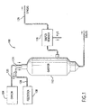
- FIG. 1 illustrates a gasification system 100 in accordance with one embodiment of the present invention.
- the gasification system 100 comprises an oxygen unit 104, a feedstock unit 108, a gasifier 112 and a sulfur remover 116.
- the oxygen unit 104 can be an air separation unit (ASU) that receives air from the atmosphere and produces oxygen.
- ASUs are sold by various manufacturers, such as Praxair and Air Products.
- the oxygen unit 104 is typically connected to the gasifier 112 via one or more oxygen lines 120.
- the gasification system 100 may have a plurality of gasifiers 112.
- the plurality of gasifiers may be connected to an ASU via an oxygen header (a main line).
- the oxygen is distributed among the various gasifiers via the oxygen header.
- the oxygen lines 120 terminate in one or more oxygen injectors in the gasifier 112.
- the oxygen injectors inject the oxygen into the gasifier 112.
- the oxygen lines 120 also include one or more oxygen valves 124.
- the oxygen valves 124 are adjusted to control the flow of oxygen to the gasifier 112.
- the feedstock unit 108 is connected to the gasifier 112 via one or more feed lines 128.
- the feedstock is supplied to the gasifier 112 via the feed lines 128.
- the feed lines 128 terminate in one or more feed injectors in the gasifier 112 that inject the feedstock into the gasifier 112.
- the feed lines 120 also include one or more feed valves 132. If gaseous feedstocks are used, the feed valves 132 are adjusted to control the flow of gaseous feedstock into the gasifier 112. In contrast, when solid or liquid feedstocks are used, their flow is controlled by the speed of a variable speed charge pump.
- the gasification system 100 can be designed to process solids (for example, coal, petroleum coke, plastic, rubber), liquids (for example, heavy oil, orimulsion, refinery by-products) or gases (for example, natural gas, refinery exhaust gas).
- Solids for example, coal, petroleum coke, plastic, rubber
- liquids for example, heavy oil, orimulsion, refinery by-products
- gases for example, natural gas, refinery exhaust gas.
- Gaseous feed stocks are directly fed into the gasifier 112, where they are mixed with the oxygen.
- Liquid feed stocks are generally pumped into the gasifier 112.
- solid feedstocks are generally ground into fine particles and mixed with water or waste oil to form a slurry prior to being fed into the gasifier 112.
- the slurry is then pumped into the gasifier 112 by a slurry pump and is fed into the gasifier 112 by the feed injectors.
- the slurry flow into the gasifier 112 can also be controlled by adjusting the speed of the slurry pump.
- Moderators such as, steam and recycled black-water, are added to the feed stock and the oxygen prior to gasification.
- the addition of moderators increases the efficiency of the gasifier 112.
- Steam is typically supplied via steam lines.
- Black-water is the water collected from the bottom of the gasifier, and is pumped back into the gasifier as a moderator.
- the gasifier 112 is a refractory lined vessel that is designed to withstand high temperature and high pressure.
- the gasifier 112 has no moving parts or any atmospheric release points.
- the feedstock and the oxygen mixture, or the "feed mix” are exposed to a temperature of approximately 1371°C (2500 degrees F) and a pressure of up to approximately 1 ⁇ 3 MPa (1200 psi).
- the feed mix breaks down into a gaseous mixture having two main components, H 2 and CO. This gaseous mixture of mainly H 2 and CO is known as the synthesis gas or "syngas.”
- the syngas may be passed through a syngas scrubber where the syngas is rinsed.
- the syngas contains heat that can be used to generate steam.
- the gaseous mixture also includes small quantities of hydrogen sulfide (H 2 S), ammonia, methane, and other by-products of the feed mix.
- H 2 S hydrogen sulfide
- ammonia ammonia
- methane methane
- other by-products of the feed mix The gaseous mixture is then passed through a sulphur remover 116 where H 2 S is removed from the gas.
- the syngas is transported from the sulfur remover 116 by a syngas header 136.
- the syngas can be burned as a fuel to generate power.
- the syngas is used to produce fertilizers, plastics and other chemicals.
- the present invention is directed to an integrated control system for the gasification plant 100.
- the integrated control system controls the gasifier 112 and other associated components, such as the ASU, the oxygen header, the syngas header and the moderator.
- the critical control system is a part of a distributed control system that controls the operation of the gasification system 100.
- FIG. 2 is a block diagram of a distributed control system 200 that controls the operation of the gasification system 100.
- a distributed control network 204 forms the backbone of the distributed control system 200.
- One or more cathode ray tube (CRT) stations 208 are connected to the network 204.
- the CRT stations 208 display the current state of the gasification system 100. Operators monitor the operation of the gasifier 112 and other components via the CRT stations 208.
- CRT cathode ray tube
- An application station 212 is connected to the network 204. Operators generally run supervisory applications, e.g., monitoring alarms, monitoring pumps, via the application station 212.
- An integrated control system (ICS) 216 is connected to the network 204.
- the ICS 216 comprises a computer microprocessor and one or more random access memories (RAMs).
- the ICS 216 controls the operation of the gasifier 112 and other critical components of the gasification system 100.
- the RAM stores one or more programs specifically developed for the ICS 216.
- the computer microprocessor executes the programs stored in the RAMs.
- One or more input/output (I/O) cards are connected to the ICS 216.
- the I/O cards provide an interface between the microprocessor and various sensors, valves and pump motor speed controllers.
- One or more non-critical control systems 220 are also connected to the network 204.
- the non-critical control systems 220 control the non-critical components of the gasification system 100.
- a communication gateway 224 is connected to the network 204.
- the gateway 224 enables the network 204 to communicate with third party systems, for example, a safety instrumentation system or an emergency shutdown system.
- FIG. 3 is a high-level block diagram of the ICS 216 in accordance with one embodiment of the present invention.
- the ICS 216 comprises an oxygen to carbon (O/C) ratio control system 304, an ASU control system 308, a moderator control system 312, and a syngas header control system 316. Each of these systems is described in detail below.
- O/C oxygen to carbon
- optimum hydrocarbon conversion occurs when the O/C ratio is controlled during gasification.
- the O/C ratio must be continuously monitored and automatically controlled. Without continuous O/C control, the O/C ratio can become too high or too low. If the O/C ratio becomes too high, the temperature inside the gasifier 112 varies widely, which reduces the gasifier's refractory life and thermocouple life. On the other hand, if the O/C ratio becomes too low, hydrocarbon conversion drops, thereby reducing the efficiency of the gasifier 112. A low O/C ratio also increases the amount of solids produced in the gasifier 112, which causes a gasifier shutdown if the solids are not removed quickly.
- the present invention provides a novel O/C ratio control that improves the performance of the gasifier 112. Also, the present invention provides safer operation and increased component life of the gasification system 100 by minimizing temperature variations in the gasifier 112. If an ASU is integrated with a gasification system 100, the O/C control system must be coupled to O 2 compressor controls in the ASU for steady operation of the gasifier 112 and the O 2 compressor.
- the O/C ratio is determined by calculating the oxygen and carbon flow signal.
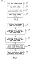
- FIG. 4 is a flow diagram of a method for controlling the O/C ratio in accordance with one embodiment of the present invention.
- a syngas demand is determined based on load constraints.
- the syngas demand is the desired output of the gasifier 112.
- the actual calculation of the syngas demand is explained in detail in FIG. 5.
- the load constraints are limiting factors in the feed mix that limit the performance of the gasifier 112.
- the load constraint calculation is also explained in greater detail in FIG. 6.
- an oxygen setpoint value is determined based on an O/C setpoint value and the syngas demand.
- the O/C setpoint value calculation is described in further detail later.
- a carbon setpoint value is determined based on the O/C setpoint value and the syngas demand.
- the oxygen flow is controlled by adjusting the oxygen valves. The oxygen valves are adjusted based on the oxygen setpoint value.
- the carbon flow is adjusted based on the carbon setpoint value.
- FIG. 5 illustrates the step 404 (calculating the syngas demand) in further detail.
- a carbon flow rate is converted to a demand controller signal by a macro unit conversion.
- an oxygen flow rate is converted to a demand controller signal by a macro unit conversion to minimize ASU fluctuations.
- the demand controller signal is represented by a pure carbon mass flow in tons/day.
- the carbon flow rate (the elemental slurry flow) is measured by a magnetic meter or by a variable speed charge pump.
- the demand controller signal and a demand controller setpoint value are received at a proportional integral derivative (PID) controller.
- PID proportional integral derivative
- the demand controller setpoint value is a desired value and is generally entered by an operator.
- the operation of a PID controller is well understood by persons skilled in the relevant art.
- the PID controller calculates an error signal that represents the difference between a signal and a setpoint value (or a reference signal), and multiplies the error signal by a gain.
- the output of the PID controller is a value between 0.0 and 1.0 (0% to 100%).
- the PID controller calculates the error signal that represents the difference between the demand controller signal and the demand controller setpoint value, and multiplies the error signal by a gain.
- a signal selector receives the output of the PID controller and an automatic demand value.
- the determination of the automatic demand value is explained in detail later.
- the signal selector selects either the output of the PID controller or the automatic demand value as the selected demand value.
- the signal selector selects the PID controller output.
- the signal selector selects the automatic demand value.
- the signal selector selects the higher of the two inputs.
- a low selector receives the selected demand value, that is, the output of the signal selector, and a syngas demand override value. The determination of the syngas demand override value is described later.
- the low selector selects the lower of the selected demand value and the syngas demand override value as a load constrained demand value.
- the load constrained demand value is converted to a bias signal.
- the oxygen flow rate is biased by the bias signal.
- the biased oxygen flow rate is the syngas demand signal.
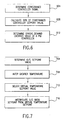
- FIG. 6 is a flow diagram of the method for determining the load constraints or the "syngas demand override value" in accordance with one embodiment of the present invention.
- a high selector selects the highest value among the following values: (1) a feed pump setpoint value; (2) a feed pump power PV/SP, where PV/SP is the actual measured power to the maximum allowable power ratio; (3) an oxygen compressor power PV/SP; (4) a gasifier oxygen valve position value (this value is used only if an integrated ASU is not used); (5) a compressor suction vent valve position value or an oxygen pump recycle valve position value (this value is used only if an integrated ASU is used); and (6) an oxygen compressor suction valve position value (this value is only used if an integrated ASU is used).
- the high selector outputs the highest value as a constrained controller signal.
- a constrained controller setpoint value is multiplied by 98% (or 0.98) at a multiplier. Although, 0.98 is the preferred factor, other factors (e.g., 0.95, 0.90) may also be used.
- the constrained controller setpoint value is the desired value and is entered by the operator.
- a PID controller receives the constrained controller signal from the high selector and the output from the multiplier (98% of the constrained controller setpoint value).
- the output of the PID controller is the syngas demand override value.
- FIG. 7 is a flow diagram of the method for determining the O/C setpoint value according to one embodiment of the present invention.
- the oxygen flow rate is divided by the carbon flow rate at a divider to obtain the O/C ratio value.
- a step 708 the measured O/C setpoint value from the step 704 is used to infer the gasifier temperature.
- a linear interpolation method is used to infer the gasifier temperature.
- the inferred gasifier temperature is the virtual temperature signal.
- a step 712 the operator uses the virtual temperature signal to select a virtual temperature setpoint value.
- the O/C ratio setpoint is interpolated from the virtual temperature setpoint value.
- FIG. 8 is a flow diagram of a method for calculating the oxygen setpoint value in accordance with one embodiment of the present invention.
- the O/C setpoint value is multiplied by the carbon flow rate at a first multiplier.
- the output of the first multiplier is a carbon flow rate in an oxygen basis (or an oxygen setpoint high limit).
- the syngas demand signal biassed oxygen flow rate from step 524 in FIG. 5
- the low selector outputs an oxygen demand constrained by the carbon flow rate.
- the output of the first multiplier i.e., the oxygen setpoint high limit
- a second multiplier where it is further multiplied by a factor 0.98.
- the output of the second multiplier is an oxygen setpoint low limit.
- the oxygen setpoint low limt is set at 98% of the oxygen setpoint high limit, it should be understood that other factors (e.g., 95%, 90%) may also be used to set the oxygen setpoint high limit.
- the oxygen setpoint low limit and the output of the low selector that is, the oxygen demand constrained by the carbon flow rate
- the high selector outputs a constrained oxygen setpoint value.
- the oxygen flow rate is constrained between 98% and 100% of the carbon flow rate.
- the carbon flow rate leads the oxygen flow rate but by no more than 2%.
- the oxygen flow rate can be constrained between other percentage values of the carbon flow rate. In other words, the carbon flow rate can be allowed to lead the oxygen flow rate by other percentage values.
- F(x) is an oxygen setpoint modifier that is used to drive the oxygen valves fully open, that is, out of control, when the oxygen is controlled at the ASU.
- F(x) is multiplied by the output of the high selector, i.e., the constrained oxygen setpoint value, to obtain the oxygen control setpoint value.
- the carbon setpoint value is calculated from a constrained carbon setpoint and the O/C ratio setpoint.
- FIG. 9 is a flow diagram of a method for determining the carbon control setpoint value.
- the oxygen flow rate and the syngas demand is received at a high selector.
- the high selector outputs a carbon set point low limit in an oxygen basis.
- the oxygen flow rate is multiplied by 1.02 at a multiplier.
- the output of the multiplier is a carbon setpoint high limit. It should be understood that the oxygen flow rate can be multiplied by other numbers, e.g., 1.05, 1.1, to set the carbon setpoint high limit.
- a step 912 the carbon setpoint high limit and the carbon setpoint low limit are received at a low selector.
- the low selector outputs the constrained carbon setpoint.
- the constrained carbon setpoint is divided by the O/C ratio setpoint and the carbon control setpoint value is obtained.
- FIG. 10 is a flow diagram for the oxygen flow control.
- a step 1004 the oxygen temperature, the oxygen pressure and the oxygen flow rate are received at a flow compensator.
- the oxygen temperature is measured from thermocouples in the oxygen lines.
- the oxygen pressure is measured by pressure transmitters in the oxygen lines.
- the oxygen flow rate is measured by oxygen flow transmitters in the oxygen lines.
- the flow compensator corrects the oxygen flow based on pressure and temperature variations.
- the compensated oxygen flow is calculated by the following equation: where,
- the flow compensator outputs a compensated oxygen flow.
- the compensated oxygen flow is converted to a molar oxygen flow.
- a step 1012 the molar oxygen flow is multiplied by the oxygen purity value at a multiplier.
- the oxygen purity value (for example, 96%) is obtained from an oxygen purity analyzer.
- the multiplier outputs an oxygen flow signal.
- the oxygen flow signal and an oxygen control setpoint value is received at a PID controller.
- the output of the PID controller is received by two velocity limiters, an increase velocity limiter and a decrease velocity limiter.
- the output of the PID controller is rate limited by one of the two velocity limiters, depending on the rate of change of the output. If the output of the PID controller is increasing (i.e., positive rate of change), then it is rate limited by the increase velocity limiter. On the other hand, if the output of the PID controller is decreasing (i.e., negative rate of change), then it is rate limited by the decrease velocity limiter.
- a step 1024 the output of the two velocity limiters are received at a signal selector, and the signal selector selects one of the signals based on whether the rate of change of the signal is positive or negative. If the output of the PID controller is increasing, the signal selector selects the increase velocity limiter. If the output of the PID controller is decreasing, the signal selector selects the decrease velocity limiter. The output of the signal selector is used to adjust the oxygen valve position.
- the carbon flow rate into the gasifier 112 is controlled by the carbon pump speed.
- the carbon pump speed is controlled by a measured carbon flow rate and a desired carbon control setpoint.
- a PID controller is used to adjust the carbon pump speed.
- FIG. 11 is a flow diagram of a method for carbon flow controls.
- the carbon flow rate is determined from the charge pump speed.
- a signal selector receives the inferred carbon flow rate and the measured carbon flow rate.
- the measured carbon flow rate is obtained from a magnetic flow meter.
- the signal selector selects one of the signals depending on the operating condition.
- the signal selector outputs the actual carbon flow rate.
- the carbon flow rate is converted to a molar carbon flow rate at a molar converter.
- Q carbon flow in gal/min
- F elemental carbon flow in lb-mol/hr
- S g specific gravity of carbon
- X c carbon content of the liquid.
- the molar conversion takes into account the velocity limited carbon content and the velocity limited slurry concentration.
- the velocity limited carbon content and the velocity limited slurry concentration is explained below.
- the carbon content is determined from the shipment of the feedstock, e.g., coke.
- the carbon content is then velocity limited or "rate limited" by a velocity limiter. For example, if the carbon content of the current shipment of the feedstock differs significantly, e.g., by 20%, from the carbon content of the previous shipment that was used in the gasifier, then the velocity limiter limits the rate of change to, for example, .05% per minute. In other words, the velocity limiter informs the carbon flow controls that the carbon content is changing only at a rate of, for example, .05% per minute rather than a drastic sudden change of 20%.
- the slurry concentration is determined by lab analysis and is likewise rate limited.
- a step 1116 the molar carbon flow rate is multiplied by the velocity limited slurry concentration at a first multiplier.
- the first multiplier output is again multiplied by the velocity limited carbon content at a second multiplier.
- the output of the second multiplier is a carbon flow signal.
- a PID controller receives the carbon flow signal and the carbon control setpoint value and outputs the carbon pump speed.
- the output of the PID controller is generally rate limited by a velocity limiter to protect the carbon pump.
- the oxygen is supplied by the ASU to the gasifier.
- an oxygen line is split into two lines prior to being fed into the gasifier 112.
- the two oxygen lines and a carbon line (from the feedstock unit) merge to form three concentric pipes in a feed injector.
- the center pipe supplies oxygen.
- the intermediate pipe surrounding the center pipe supplies feedstock.
- the outer pipe surrounding the intermediate pipe supplies oxygen.
- the oxygen is controlled by two valves. A center oxygen valve located prior to the split, that is, up-stream, and an annular oxygen valve located in the concentric section, that is, down-stream, of the pipe.
- FIG. 12 is flow diagram for feed injector controls.
- a step 1204 an annular oxygen split value is determined.
- the oxygen split setpoint value is multiplied by the compensated oxygen flow signal at a first multiplier.
- the first multiplier outputs the oxygen setpoint value.
- the annular oxygen split signal is multiplied by the compensated oxygen flow signal at a second multiplier and an annular oxygen setpoint value is obtained.
- the oxygen split signal is subtracted from the oxygen flow signal to obtain the annular oxygen flow signal.
- the oxygen flow signal is measured by transmitters in the oxygen line.
- the annular oxygen flow signal and the annular oxygen setpoint is received at a PID controller.
- the PID controller outputs an annular oxygen valve position.
- the oxygen flow signal and the oxygen setpoint value is received at a PID controller that outputs a center oxygen valve position.
- moderators are added to the oxygen and the feedstocks before they are fed into the gasifier 112.
- steam is added to the oxygen and the feedstock.
- recycled black-water may be added to the feedstock.
- Black-water is the water collected from the bottom of the gasifier which is then added to the carbon as a moderator.
- black-water collected from the gasifier is pumped back as a moderator by a pump.
- the amount of moderators in the oxygen and carbon is controlled by adjusting the oxygen line steam valve and the carbon line steam valve. If recycled black-water is also used as a moderator, the amount of black-water is controlled by adjusting the speed of a recycled black-water pump.
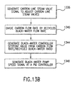
- FIGS. 13A and 13B illustrate a flow diagram for controlling the moderator in the gasifier 112.
- a step 1304 the oxygen line steam flow rate, the steam temperature and the steam pressure are received at a first flow compensator.
- the oxygen line steam flow rate is measured by a flow meter in the steam line.
- the steam temperature is measured by one or more thermocouples in the steam line.
- the steam pressure is measured by one or more pressure transmitters in the steam line.
- the flow compensator outputs an oxygen line steam flow signal that is compensated for the steam pressure and the steam temperature.
- the compensated steam flow signal is calculated by the following equation: where,
- a step 1308 the carbon line steam flow rate, the steam pressure and the steam temperature are received at second flow compensator, and the flow compensator outputs a compensated carbon line steam flow signal.
- the compensated oxygen line steam flow signal and the compensated carbon line steam flow signal are added at a first adder and a total steam flow signal is generated.
- the total steam flow is added to the recycled black-water flow rate and the total moderator flow rate is determined. In one embodiment, the black-water flow rate is measured by a magnetic meter in the carbon line.
- a step 1320 the total moderator flow rate is divided by the carbon flow rate at a first divider, and a moderator/carbon ratio is generated.
- the moderator/carbon ratio, the carbon flow rate and a moderator/carbon ratio setpoint value is received at a first ratio controller.
- the ratio controller outputs a desired oxygen line steam rate by comparing the moderator/carbon ratio signal and the moderator/carbon ratio setpoint value.
- a ratio controller typically follows a desired ratio by varying one component of a ratio while the other component of the ratio remains fixed until the desired ratio is achieved. The following example illustrates the operation of a ratio controller.
- a desired ratio is 2/3 or .666.
- a ratio controller receives a ratio x / y .
- the ratio controller can vary x while y remains fixed.
- the desired oxygen line steam rate may be replaced by a predetermined value at a safety system setpoint override.
- the oxygen line steam flow signal and the output from the safety system setpoint override are received at a first PID controller.
- the first PID controller outputs the oxygen line steam valve signal that is used to adjust the oxygen line steam valves.
- a step 1336 the compensated carbon line steam flow signal and a carbon line steam flow setpoint are received at a second PID controller.
- the PID controller outputs a carbon line steam valve signal that is used to adjust the carbon line steam valves.
- a step 1340 the carbon flow rate is divided by the recycled black-water flow rate at a second divider.
- a second ratio controller generates a black-water controller setpoint value from the output of the divider.
- a third PID controller receives the recycled black-water flow rate and the black-water controller setpoint value, i.e., the output of the second ratio controller. The third PID controller outputs a recycled black-water pump speed signal that is used to control the speed of the recycled black-water pump.
- the present invention provides an ASU/Oxygen Controls where an ASU is integrated with the gasification system 100.
- the oxygen discharge from the ASU is controlled by adjusting an oxygen compressor inlet valve.
- FIGS. 14A and 14B illustrate a flow diagram for the ASU/Oxygen Controls in accordance with one embodiment of the present invention.
- step 1404 the oxygen valve position of the gasifier 112 and other gasifiers that may be operating simultaneously are compared at a high selector.
- F(x) is an oxygen setpoint modifier that is used to restrict oxygen at the ASU to cause the downstream gasifier oxygen valves to open to the point where they release control of the oxygen to the ASU.
- F(y) 0.002y + 0.81, where F(y) > 1.0, and y is the oxygen valve position of the gasifier 112.
- F(y) is an oxygen setpoint modifier used to counteract the oxygen setpoint modifier F(x) of the step 820.
- a step 1416 the actual oxygen setpoint value is divided by F(y) at a divider.
- the actual oxygen setpoint value is calculated by the operator and entered into the system.
- the output of the divider and other similar outputs from other gasifiers are added at a first adder.
- the output of the first adder is multiplied at a multiplier by F(x) obtained in step 1408.
- the multiplier outputs a discharge controller setpoint value.
- the discharge controller setpoint value represents the combined total oxygen setpoint value, that is, the discharge of the ASU.
- a PID controller receives the discharge controller setpoint and the total oxygen value setpoint.
- the PID controller outputs a discharge controller output signal.
- the output of the PID controller is velocity limited at a velocity limiter.
- the velocity limited discharge controller output signal is received at a low selector along with outputs from other ASU controllers (e.g., compressor suction flow controller, ASU suction vent controller) and compressor protection controllers.
- the output of the low selector is the oxygen compressor inlet valve signal.
- a common line known as the "oxygen header" is used to distribute oxygen among various gasifiers.
- oxygen header is vented through header valves.
- the amount of oxygen vented through the header vent valves is controlled by adjusting the header vent valves.
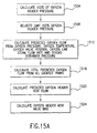
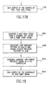
- FIGS. 15A and 15B illustrate a flow diagram for controlling the oxygen header vent valves.
- an oxygen header pressure signal is multiplied by 1.02 at a multiplier.
- the output of the multiplier is velocity limited at a velocity limiter.
- the output of the velocity limiter is the oxygen header control setpoint value.
- a predicted oxygen flow is calculated from the oxygen pressure, the oxygen temperature, the oxygen valve position, the oxygen line steam flow rate and the syngas scrubber pressure.
- the oxygen pressure is measured by one or more pressure transmitters in the oxygen line.
- the oxygen temperature is measured by one or more thermocouples in the oxygen line.
- the oxygen line steam flow rate calculation was described earlier.
- the syngas scrubber pressure is measured by a pressure transmitter in a syngas scrubber.
- the predicted oxygen flow can be calculated by treating the gasifier oxygen valve and the gasifier feed injector as two restrictions in series.
- the flow through a restriction is a function of the upstream and down stream pressures and the size of the restrictions.
- the down stream pressure for the feed injector is the syngas gas scrubber pressure.
- the upstream pressure for the feed injector cannot be directly measured. So it is instead inferred from the steam flow to the oxygen line upstream of the feed injector.
- the inferred pressure also serves as the downstream pressure for the oxygen valve restriction. As the oxygen valve opens and closes, the value of its restriction changes. Multiple iterative equations must be used to determine the impact of the oxygen valves when it is above or below its designed normal position.
- the predicted oxygen flow is calculated by the equation provided below.
- the predicted oxygen pressure is constraint by: P oxygen - 10 > P > P scrubber + 10, where:
- a step 1516 the predicted oxygen flow is added to predicted oxygen flows from other gasifier trains at an adder.
- the total predicted oxygen flow is subtracted from the design oxygen header flow value and a predicted oxygen header vent flow is obtained.
- the design oxygen header flow value is a constant, which represents the amount of oxygen that the oxygen pipes are designed to carry.
- an oxygen header vent valve bias value is calculated from the predicted oxygen header vent flow and an oxygen header vent valve critical flow. The oxygen header vent valve bias calculation is described in the Texaco Design Document.
- the oxygen header vent valve critical flow is the maximum allowable flow through the vent valve.
- a PID controller receives the oxygen header control setpoint value and the oxygen header pressure signal.
- the PID controller outputs an unbiased oxygen header vent valve signal.
- the output of the PID controller is biased by the oxygen header valve bias value and a biased oxygen header vent valve signal is obtained.
- the oxygen header vent valve signal is used to adjust the vent valves of the oxygen header.
- the syngas is transported from the gasifier by one or more syngas headers.
- the operator enters a normal pressure control setpoint, also called the syngas header pressure setpoint.
- the syngas header pressure setpoint is then used for high pressure control, low pressure control and "low low" pressure control.
- FIG. 16 is a flow diagram of a method for determining the normal pressure control of the syngas header.
- the syngas header pressure signal is measured by one or more pressure transmitters in the syngas header.
- a PID controller receives the syngas header pressure setpoint and the syngas header pressure signal.
- the PID controller outputs a boiler syngas setpoint value.
- the boiler refers to a boiler downstream of the gasifier, which intakes the syngas and bums the syngas to generate power.
- the boiler syngas setpoint value represents the amount of syngas the boiler should consume.
- FIGS. 17A and 17B illustrate a flow diagram for a high pressure control of the syngas header.
- the syngas header flow rate, the syngas header temperature and the syngas header pressure signal are received at a flow compensator.
- the flow compensator calculates a compensated syngas header flow.
- a syngas header flare vent valve bias is calculated from the compensated syngas header flow, the syngas header temperature and the maximum allowable flow through syngas header valve.
- a step 1712 the syngas header flare vent valve bias and a combustion turbine trip signal is received at a bias ramp.
- the output of the bias ramp is added to other combustion turbine trip signals from other turbines at an adder.
- the syngas header pressure setpoint is multiplied by 1.02 at a multiplier. The output of the multiplier is the high pressure setpoint.
- the syngas header pressure signal and the high pressure setpoint are received at a PID controller. The PID controller outputs when the syngas header pressure increases by more than 2% of the high pressure setpoint.
- the output of the PID controller is biased by the output of the adder and the syngas header flare vent valve position is obtained.
- FIG. 18 is a flow diagram of the method for a low pressure control of the syngas header.
- a gasifier trip signal and a ramp start signal is received at a bias ramp.
- the ramp start signal is entered by the operator.
- the syngas header pressure setpoint is multiplied by 0.98 at a multiplier and a low pressure setpoint. In other words, the low pressure setpoint is set at 98% of the syngas header pressure setpoint.
- a PID controller receives the syngas header pressure signal and the low pressure setpoint and outputs an unbiased low syngas pressure signal.
- the unbiased low syngas pressure signal is biased by the output of the bias ramp to obtain the low syngas presure signal.
- FIG. 19 is a flow diagram of a method for a gasification pressure control.
- a gasifier trip signal and a ramp start signal is received at a bias ramp.
- the gasifier trip signal is produced when there is a gasifier shutdown.
- the ramp start signal is a constant value.
- the bias ramp generates a bias signal that will be used to unload gasifier syngas inventory into the syngas header.
- a step 1908 the high pressure setpoint value is multiplied by 0.98 at a multiplier.
- the output of the multiplier is biased by the output of the bias ramp, i.e., the bias signal, and the normal pressure setpoint value is obtained.
- a first PID controller receives a scrubber pressure and the high pressure setpoint. The scrubber pressure is measured by pressure transmitters in the overhead of the syngas scrubber. The first PID controller outputs a flare valve position.
- a second PID controller receives the scrubber pressure and the normal pressure setpoint and generates a syngas letdown valve controller signal.
- the automatic demand value noted earlier is derived from the carbon pump speed and the low syngas pressure signal.
- FIG. 20 is a flow diagram of a method for determining the automatic demand.
- a step 2004 the speed differential of two carbon pumps (from two gasifier trains) is calculated. The difference represents a predicted train differential.
- a PID controller receives the predicted train differential and a zero (0) setpoint value. The output of the PID controller is between 0 and 100%.
- the output of the PID controller is converted to a bias value. In one embodiment, the output of the PID controller is converted to a value between -10 and +10.
- the low syngas pressure signal is biased by the bias value and the automatic demand is generated.
- the bias value is multiplied by -1 and is provided to the other gasification train as an automatic demand.
- the ICS 216 is implemented by a computer system capable of carrying out the functionality of the ICS 216 described above, and is shown in more detail in FIG. 21.
- a computer system 2100 includes one or more processors, such as a processor 2104.
- the processor 2104 is connected to a communication bus 2108.
- Various software embodiments are described in terms of this exemplary computer system. After reading this description, it will become apparent to a person skilled in the relevant art how to implement the invention using other computer systems and/or computer architectures.
- the computer system 2100 also includes a main memory 2112, preferably a random access memory (RAM), and can also include a secondary memory 2116.
- the secondary memory 2116 can include, for example, a hard disk drive 2120 and/or a removable storage drive 2124, representing a floppy disk drive, a magnetic tape drive, an optical disk drive, etc.
- the removable storage drive 2124 reads from and/or writes to a removable storage unit 2132 in a well known manner.
- the removable storage unit 2132 represents a floppy disk, magnetic tape, optical disk, etc. which is read by and written to by the removable storage drive 2124.
- the removable storage unit 2132 includes a computer usable storage medium having stored therein computer software and/or data.
- the secondary memory 2116 may include other similar means for allowing computer programs or other instructions to be loaded into the computer system 2100.
- Such means can include, for example, a removable storage unit 2134 and an interface 2128. Examples of such can include a program cartridge and cartridge interface (such as that found in video game devices), a removable memory chip (such as an EPROM, or PROM) and associated socket, and other removable storage units 2134 and interfaces 2128 which allow software and data to be transferred from removable storage unit 2134 to the computer system 2100.
- the computer system 2100 can also include a communications interface 2136.
- the communications interface 2136 allows software and data to be transferred between the computer system 2100 and external devices. Examples of the communications interface 2100 can include a modem, a network interface (such as an Ethernet card), a communications port, a PCMCIA slot and card, etc.
- Software and data transferred via the communications interface 2136 are in the form of signals 2140 that can be electronic, electromagnetic, optical or other signals capable of being received by the communications interface 2136.
- the signals 2140 are provided to communications interface via a channel 2144.
- the channel 2144 carries the signals 2140 and can be implemented using wire or cable, fiber optics, a phone line, a cellular phone link, an RF link and other communications channels.
- computer program medium and “computer usable medium” are used to generally refer to media such as the removable storage drive 2124, a hard disk installed in the hard disk drive 2120, and the signals 2140. These computer program products are means for providing software to the computer system 2100.
- Computer programs are stored in the main memory 2112 and/or the secondary memory 2116. Computer programs can also be received via the communications interface 2136. Such computer programs, when executed, enable the computer system 2100 to perform the features of the present invention as discussed herein. In particular, the computer programs, when executed, enable the processor 2104 to perform the features of the present invention.
- the software may be stored in a computer program product and loaded into the computer system 2100 using the removable storage drive 2124, the hard drive 2120 or the communications interface 2136.
- the control logic when executed by the processor 2104, causes the processor 2104 to perform the functions of the invention as described herein.
- the invention can be implemented primarily in hardware using, for example, hardware components such as application specific integrated circuits (ASICs).
- ASICs application specific integrated circuits
- the invention is implemented using a combination of both hardware and software.
Landscapes
- Chemical & Material Sciences (AREA)
- Engineering & Computer Science (AREA)
- Combustion & Propulsion (AREA)
- Organic Chemistry (AREA)
- Oil, Petroleum & Natural Gas (AREA)
- Chemical Kinetics & Catalysis (AREA)
- General Chemical & Material Sciences (AREA)
- General Health & Medical Sciences (AREA)
- Health & Medical Sciences (AREA)
- Inorganic Chemistry (AREA)
- Hydrogen, Water And Hydrids (AREA)
- Organic Low-Molecular-Weight Compounds And Preparation Thereof (AREA)
- Feedback Control In General (AREA)
- Treatment Of Sludge (AREA)
- Industrial Gases (AREA)
- Separation By Low-Temperature Treatments (AREA)
- Gasification And Melting Of Waste (AREA)
Applications Claiming Priority (3)
| Application Number | Priority Date | Filing Date | Title |
|---|---|---|---|
| US09/154,772 US6269286B1 (en) | 1998-09-17 | 1998-09-17 | System and method for integrated gasification control |
| US154772 | 1998-09-17 | ||
| PCT/US1999/020012 WO2000015737A1 (en) | 1998-09-17 | 1999-09-01 | System and method for integrated gasification control |
Publications (2)
| Publication Number | Publication Date |
|---|---|
| EP1115813A1 EP1115813A1 (en) | 2001-07-18 |
| EP1115813B1 true EP1115813B1 (en) | 2005-04-06 |
Family
ID=22552713
Family Applications (1)
| Application Number | Title | Priority Date | Filing Date |
|---|---|---|---|
| EP99944034A Expired - Lifetime EP1115813B1 (en) | 1998-09-17 | 1999-09-01 | method and computer program for gasification control |
Country Status (17)
| Country | Link |
|---|---|
| US (1) | US6269286B1 (cs) |
| EP (1) | EP1115813B1 (cs) |
| JP (1) | JP5259031B2 (cs) |
| KR (1) | KR100570316B1 (cs) |
| CN (1) | CN1131298C (cs) |
| AR (1) | AR020152A1 (cs) |
| AT (1) | ATE292664T1 (cs) |
| AU (1) | AU759801B2 (cs) |
| BR (1) | BR9913853A (cs) |
| CA (1) | CA2343035C (cs) |
| CZ (1) | CZ299517B6 (cs) |
| DE (1) | DE69924625T2 (cs) |
| ES (1) | ES2241317T3 (cs) |
| NO (1) | NO20011366L (cs) |
| PL (1) | PL194785B1 (cs) |
| WO (1) | WO2000015737A1 (cs) |
| ZA (1) | ZA200101938B (cs) |
Cited By (1)
| Publication number | Priority date | Publication date | Assignee | Title |
|---|---|---|---|---|
| US8480769B2 (en) | 2010-07-29 | 2013-07-09 | Air Products And Chemicals, Inc. | Method for gasification and a gasifier |
Families Citing this family (50)
| Publication number | Priority date | Publication date | Assignee | Title |
|---|---|---|---|---|
| ES2273023T3 (es) * | 2002-04-05 | 2007-05-01 | Shell Internationale Research Maatschappij B.V. | Metodo para controlar un procedimiento. |
| US7092893B2 (en) * | 2003-01-28 | 2006-08-15 | Praxair Technology, Inc. | Control of liquid production of air separation plant network |
| US7318970B2 (en) * | 2003-04-04 | 2008-01-15 | Texaco Inc. | Architectural hierarchy of control for a fuel processor |
| WO2006081661A1 (en) * | 2005-02-04 | 2006-08-10 | Plasco Energy Group Inc. | Coal gasification process and apparatus |
| US6993403B1 (en) * | 2005-03-22 | 2006-01-31 | Praxair Technology, Inc. | Facility monitoring method |
| US20110289845A1 (en) * | 2005-04-12 | 2011-12-01 | Ze-Gen, Inc. | Method for controlling syngas production in a system with multiple feed materials using a molten metal bath |
| JP2008545840A (ja) * | 2005-06-03 | 2008-12-18 | プラスコ エナジー グループ インコーポレイテッド | 炭素質原料から特定の構成のガスへと変換するためのシステム |
| RU2007146272A (ru) * | 2005-06-03 | 2009-06-20 | Пласко Энерджи Групп Инк., (CA) | Система для переработки угля в газ определенного состава |
| MY145411A (en) * | 2005-12-14 | 2012-02-15 | Shell Int Research | Method of controlling synthesis gas production |
| US7621973B2 (en) * | 2005-12-15 | 2009-11-24 | General Electric Company | Methods and systems for partial moderator bypass |
| US7744663B2 (en) * | 2006-02-16 | 2010-06-29 | General Electric Company | Methods and systems for advanced gasifier solids removal |
| US7562588B2 (en) * | 2006-04-27 | 2009-07-21 | Delphi Technologies, Inc. | Method and apparatus for controlling mass flow rate of recycled anode tail gas in solid oxide fuel cell system |
| NZ573217A (en) | 2006-05-05 | 2011-11-25 | Plascoenergy Ip Holdings S L Bilbao Schaffhausen Branch | A facility for conversion of carbonaceous feedstock into a reformulated syngas containing CO and H2 |
| AU2007247895A1 (en) | 2006-05-05 | 2007-11-15 | Plascoenergy Ip Holdings, S.L., Bilbao, Schaffhausen Branch | A gas homogenization system |
| EP2015859A4 (en) | 2006-05-05 | 2010-09-29 | Plascoenergy Ip Holdings Slb | GAS CONDITIONING SYSTEM |
| MX2008014199A (es) * | 2006-05-05 | 2009-09-07 | Plasco Energy Ip Holdings S L | Sistema de reformulacion de gas que usa calor de un soplete de plasma. |
| MX2008014200A (es) | 2006-05-05 | 2009-06-04 | Plasco Energy Ip Holdings S L | Gasificador orientado horizontalmente con sistema de transferencia lateral. |
| BRPI0711325A2 (pt) * | 2006-05-05 | 2011-08-30 | Plascoenergy Ip Holdings S L Bilbao Schaffhausen Branch | sistema de controle para a conversão de um estoque de alimentação carbonáceo em gás |
| US7668623B2 (en) * | 2006-08-01 | 2010-02-23 | Emerson Process Management Power & Water Solutions, Inc. | Steam temperature control using integrated function block |
| ITMI20062328A1 (it) * | 2006-12-04 | 2008-06-05 | Caema Srl | Metodo e impianto di gassificazione di biomasse per la produzione di gas combustibile |
| US20100175320A1 (en) * | 2006-12-29 | 2010-07-15 | Pacific Renewable Fuels Llc | Energy efficient system and process for the continuous production of fuels and energy from syngas |
| JP5547659B2 (ja) * | 2007-02-27 | 2014-07-16 | プラスコエナジー アイピー ホールディングス、エス.エル.、ビルバオ、シャフハウゼン ブランチ | 加工原料/チャー変換とガス改質を伴うガス化方式 |
| WO2008131209A1 (en) * | 2007-04-18 | 2008-10-30 | Ze-Gen, Inc. | Method for controlling syngas production in a system with multiple feed materials |
| US20080277265A1 (en) * | 2007-05-11 | 2008-11-13 | Plasco Energy Group, Inc. | Gas reformulation system comprising means to optimize the effectiveness of gas conversion |
| US20100154304A1 (en) * | 2007-07-17 | 2010-06-24 | Plasco Energy Group Inc. | Gasifier comprising one or more fluid conduits |
| KR101010520B1 (ko) | 2007-11-21 | 2011-01-24 | 두산중공업 주식회사 | 가스화기 운전 제어시스템 및 그의 제어방법 |
| CN101538485B (zh) * | 2009-03-20 | 2012-06-27 | 西北化工研究院 | 气流床反应器温度控制系统与其控制方法 |
| US8821598B2 (en) * | 2009-07-27 | 2014-09-02 | General Electric Company | Control system and method to operate a quench scrubber system under high entrainment |
| US20110203535A1 (en) * | 2010-02-19 | 2011-08-25 | Nrg Energy, Inc. | Method and System for Sootblower Flow Analyzer |
| US8585789B2 (en) * | 2010-04-13 | 2013-11-19 | Ineos Usa Llc | Methods for gasification of carbonaceous materials |
| US8999021B2 (en) * | 2010-04-13 | 2015-04-07 | Ineos Usa Llc | Methods for gasification of carbonaceous materials |
| US9321640B2 (en) | 2010-10-29 | 2016-04-26 | Plasco Energy Group Inc. | Gasification system with processed feedstock/char conversion and gas reformulation |
| CN102063132B (zh) * | 2011-01-07 | 2012-08-08 | 水煤浆气化及煤化工国家工程研究中心 | 粉煤加压气化装置氧煤比自动控制系统 |
| US8417361B2 (en) | 2011-03-22 | 2013-04-09 | General Electric Company | Model predictive control system and method for integrated gasification combined cycle power generation |
| US8538561B2 (en) | 2011-03-22 | 2013-09-17 | General Electric Company | Method and system to estimate variables in an integrated gasification combined cycle (IGCC) plant |
| US9381446B2 (en) | 2012-01-18 | 2016-07-05 | General Electric Company | System for deaeration in a flash vessel |
| US10071863B2 (en) | 2013-03-15 | 2018-09-11 | Mark E. Koenig | Method for processing material for a gasifier |
| US10190065B2 (en) | 2013-03-15 | 2019-01-29 | Mark E. Koenig | Feed delivery system and method for gasifier |
| WO2016061281A1 (en) * | 2014-10-14 | 2016-04-21 | Sentinel Global Product Solutions, Inc. | Co2 generator and controller |
| KR102086202B1 (ko) * | 2017-09-25 | 2020-03-06 | 한국서부발전 주식회사 | 가스화플랜트 열부하 자동제어 시스템 |
| US11105526B1 (en) | 2017-09-29 | 2021-08-31 | Integrated Global Services, Inc. | Safety shutdown systems and methods for LNG, crude oil refineries, petrochemical plants, and other facilities |
| CN109609194B (zh) * | 2018-12-27 | 2020-12-15 | 西安元创化工科技股份有限公司 | 一种多通道喷嘴的料浆和氧气进料控制方法 |
| US11312914B2 (en) | 2019-02-04 | 2022-04-26 | Eastman Chemical Company | Gasification of plastics and solid fossil fuels to produce organic compounds |
| US11447576B2 (en) | 2019-02-04 | 2022-09-20 | Eastman Chemical Company | Cellulose ester compositions derived from recycled plastic content syngas |
| GB2585870B (en) | 2019-07-18 | 2024-06-19 | Powerhouse Energy Group Plc | Treatment of waste material |
| GB2585873A (en) | 2019-07-18 | 2021-01-27 | Powerhouse Energy Group Plc | Treatment of waste material |
| GB2585872A (en) * | 2019-07-18 | 2021-01-27 | Powerhouse Energy Group Plc | Treatment of waste material |
| US12492298B2 (en) | 2019-08-26 | 2025-12-09 | Eastman Chemical Company | 2-ethylhexanoyl substituted cellulose esters |
| WO2021211525A1 (en) * | 2020-04-13 | 2021-10-21 | Eastman Chemical Company | Gasification of liquefied waste plastics |
| KR102476768B1 (ko) * | 2020-11-10 | 2022-12-13 | 해표산업 주식회사 | 가스화 장치 및 시스템 |
Family Cites Families (13)
| Publication number | Priority date | Publication date | Assignee | Title |
|---|---|---|---|---|
| DE2757032A1 (de) | 1977-12-21 | 1979-06-28 | Krupp Koppers Gmbh | Verfahren zur ermittlung des bei der partialoxydation von feinkoernigen bis staubfoermigen festen brennstoffen dem vergaser zugefuehrten brennstoffstromes |
| US4338099A (en) * | 1979-12-26 | 1982-07-06 | Texaco Inc. | Process for the partial oxidation of slurries of solid carbonaceous fuels |
| US4400179A (en) | 1980-07-14 | 1983-08-23 | Texaco Inc. | Partial oxidation high turndown apparatus |
| US4490156A (en) * | 1981-06-10 | 1984-12-25 | Texaco Inc. | Partial oxidation system |
| US4489562A (en) * | 1982-11-08 | 1984-12-25 | Combustion Engineering, Inc. | Method and apparatus for controlling a gasifier |
| US4676805A (en) | 1983-05-31 | 1987-06-30 | Texaco Inc. | Process for operating a gas generator |
| JPS61126197A (ja) * | 1984-11-22 | 1986-06-13 | Hitachi Ltd | 石炭ガス化プラント酸素量制御方式 |
| US4666462A (en) | 1986-05-30 | 1987-05-19 | Texaco Inc. | Control process for gasification of solid carbonaceous fuels |
| GB8619076D0 (en) * | 1986-08-05 | 1986-09-17 | Shell Int Research | Partial oxidation of fuel |
| US4888031A (en) * | 1988-05-26 | 1989-12-19 | Shell Oil Company | Process for partial oxidation of a liquid or solid and/or a gaseous hydrocarbon-containing fuel |
| US5087271A (en) | 1990-11-19 | 1992-02-11 | Texaco Inc. | Partial oxidation process |
| JPH08500412A (ja) | 1992-12-30 | 1996-01-16 | コンバッション エンヂニアリング インコーポレーテッド | 一体形ガス化併合サイクルシステム用の制御システム |
| EP0986623B1 (en) | 1997-06-06 | 2005-08-31 | Texaco Development Corporation | Oxygen flow control for gasification |
-
1998
- 1998-09-17 US US09/154,772 patent/US6269286B1/en not_active Expired - Fee Related
-
1999
- 1999-08-10 AR ARP990103997A patent/AR020152A1/es unknown
- 1999-09-01 PL PL346662A patent/PL194785B1/pl unknown
- 1999-09-01 DE DE69924625T patent/DE69924625T2/de not_active Expired - Lifetime
- 1999-09-01 JP JP2000570265A patent/JP5259031B2/ja not_active Expired - Lifetime
- 1999-09-01 AT AT99944034T patent/ATE292664T1/de not_active IP Right Cessation
- 1999-09-01 KR KR1020017003362A patent/KR100570316B1/ko not_active Expired - Lifetime
- 1999-09-01 EP EP99944034A patent/EP1115813B1/en not_active Expired - Lifetime
- 1999-09-01 ZA ZA200101938A patent/ZA200101938B/en unknown
- 1999-09-01 CN CN99812218A patent/CN1131298C/zh not_active Expired - Lifetime
- 1999-09-01 CA CA2343035A patent/CA2343035C/en not_active Expired - Fee Related
- 1999-09-01 CZ CZ20010830A patent/CZ299517B6/cs not_active IP Right Cessation
- 1999-09-01 BR BR9913853-0A patent/BR9913853A/pt not_active IP Right Cessation
- 1999-09-01 WO PCT/US1999/020012 patent/WO2000015737A1/en not_active Ceased
- 1999-09-01 AU AU57010/99A patent/AU759801B2/en not_active Ceased
- 1999-09-01 ES ES99944034T patent/ES2241317T3/es not_active Expired - Lifetime
-
2001
- 2001-03-16 NO NO20011366A patent/NO20011366L/no not_active Application Discontinuation
Cited By (1)
| Publication number | Priority date | Publication date | Assignee | Title |
|---|---|---|---|---|
| US8480769B2 (en) | 2010-07-29 | 2013-07-09 | Air Products And Chemicals, Inc. | Method for gasification and a gasifier |
Also Published As
| Publication number | Publication date |
|---|---|
| CN1131298C (zh) | 2003-12-17 |
| PL346662A1 (en) | 2002-02-25 |
| NO20011366L (no) | 2001-05-18 |
| JP5259031B2 (ja) | 2013-08-07 |
| CZ299517B6 (cs) | 2008-08-20 |
| AU5701099A (en) | 2000-04-03 |
| AR020152A1 (es) | 2002-04-10 |
| CA2343035C (en) | 2012-07-10 |
| DE69924625D1 (de) | 2005-05-12 |
| AU759801B2 (en) | 2003-05-01 |
| CA2343035A1 (en) | 2000-03-23 |
| US6269286B1 (en) | 2001-07-31 |
| KR100570316B1 (ko) | 2006-04-12 |
| CN1323340A (zh) | 2001-11-21 |
| NO20011366D0 (no) | 2001-03-16 |
| ZA200101938B (en) | 2001-09-11 |
| CZ2001830A3 (cs) | 2001-10-17 |
| JP2002524653A (ja) | 2002-08-06 |
| ES2241317T3 (es) | 2005-10-16 |
| EP1115813A1 (en) | 2001-07-18 |
| WO2000015737A1 (en) | 2000-03-23 |
| DE69924625T2 (de) | 2006-02-02 |
| BR9913853A (pt) | 2001-07-17 |
| KR20010088805A (ko) | 2001-09-28 |
| PL194785B1 (pl) | 2007-07-31 |
| ATE292664T1 (de) | 2005-04-15 |
Similar Documents
| Publication | Publication Date | Title |
|---|---|---|
| US6269286B1 (en) | System and method for integrated gasification control | |
| JP2002524653A5 (cs) | ||
| CN101807069B (zh) | 一种湿法气流床煤气化工艺过程的控制系统 | |
| US20110190939A1 (en) | Control and optimization system and method for chemical looping processes | |
| EP2080878A1 (en) | Gas turbine power generation system and method of detecting its calorie abnormality | |
| CN101449040A (zh) | 煤气复合发电系统及其运转控制方法 | |
| CN101346537A (zh) | 使用费托技术提供辅助电力到发电站的改良的方法 | |
| KR101739678B1 (ko) | 가스화 발전 플랜트의 제어장치, 가스화 발전 플랜트, 및 가스화 발전 플랜트의 제어방법 | |
| EP4237375A1 (en) | Control of an ammonia synthesis loop at partial load | |
| AU2003231326B2 (en) | System and method for integrated gasification control | |
| US9427703B2 (en) | CO2 separation and recovery equipment, and a coal gasification combined power plant comprising CO2 separation and recovery equipment | |
| EP1798385B1 (en) | Integrated gasification combined cycle and method of controlling thereof | |
| CN100593672C (zh) | 燃气轮机设备、燃料气体供给设备及燃料气体的发热量上升抑制方法 | |
| US7452393B2 (en) | Installation for hydrogen production and methods for using same | |
| US20120247113A1 (en) | System and method for air extraction from gas turbine engines | |
| AU739547B2 (en) | Oxygen flow control for gasification | |
| MXPA01002956A (en) | System and method for integrated gasification control | |
| RU2817818C1 (ru) | Управление контуром синтеза аммиака при неполной нагрузке | |
| JP5000223B2 (ja) | 圧縮機の制御装置及び石炭ガス化発電システム | |
| CA2291632A1 (en) | Air extraction in a gasification process | |
| EP4516739A1 (en) | Control of ammonia or methanol synthesis loop at partial load | |
| JP2019156984A (ja) | ガス精製装置 | |
| JPH02298633A (ja) | 石炭ガス化コンバインドサイクル発電プラント | |
| TC12 | PSDF | |
| Millar | Optimising a multi-mode steam distribution system |
Legal Events
| Date | Code | Title | Description |
|---|---|---|---|
| PUAI | Public reference made under article 153(3) epc to a published international application that has entered the european phase |
Free format text: ORIGINAL CODE: 0009012 |
|
| 17P | Request for examination filed |
Effective date: 20010306 |
|
| AK | Designated contracting states |
Kind code of ref document: A1 Designated state(s): AT BE CH CY DE DK ES FI FR GB GR IE IT LI LU MC NL PT SE |
|
| AX | Request for extension of the european patent |
Free format text: AL;LT;LV;MK;RO;SI |
|
| RIN1 | Information on inventor provided before grant (corrected) |
Inventor name: WALLACE, PAUL, S. Inventor name: GULKO, GEORGE, M. Inventor name: TSE, DANIEL, W. |
|
| 17Q | First examination report despatched |
Effective date: 20030520 |
|
| GRAP | Despatch of communication of intention to grant a patent |
Free format text: ORIGINAL CODE: EPIDOSNIGR1 |
|
| RTI1 | Title (correction) |
Free format text: METHOD AND COMPUTER PROGRAM FOR GASIFICATION CONTROL |
|
| GRAS | Grant fee paid |
Free format text: ORIGINAL CODE: EPIDOSNIGR3 |
|
| GRAA | (expected) grant |
Free format text: ORIGINAL CODE: 0009210 |
|
| AK | Designated contracting states |
Kind code of ref document: B1 Designated state(s): AT BE CH CY DE DK ES FI FR GB GR IE IT LI LU MC NL PT SE |
|
| PG25 | Lapsed in a contracting state [announced via postgrant information from national office to epo] |
Ref country code: NL Free format text: LAPSE BECAUSE OF FAILURE TO SUBMIT A TRANSLATION OF THE DESCRIPTION OR TO PAY THE FEE WITHIN THE PRESCRIBED TIME-LIMIT Effective date: 20050406 Ref country code: LI Free format text: LAPSE BECAUSE OF FAILURE TO SUBMIT A TRANSLATION OF THE DESCRIPTION OR TO PAY THE FEE WITHIN THE PRESCRIBED TIME-LIMIT Effective date: 20050406 Ref country code: FI Free format text: LAPSE BECAUSE OF FAILURE TO SUBMIT A TRANSLATION OF THE DESCRIPTION OR TO PAY THE FEE WITHIN THE PRESCRIBED TIME-LIMIT Effective date: 20050406 Ref country code: CH Free format text: LAPSE BECAUSE OF FAILURE TO SUBMIT A TRANSLATION OF THE DESCRIPTION OR TO PAY THE FEE WITHIN THE PRESCRIBED TIME-LIMIT Effective date: 20050406 Ref country code: BE Free format text: LAPSE BECAUSE OF FAILURE TO SUBMIT A TRANSLATION OF THE DESCRIPTION OR TO PAY THE FEE WITHIN THE PRESCRIBED TIME-LIMIT Effective date: 20050406 Ref country code: AT Free format text: LAPSE BECAUSE OF FAILURE TO SUBMIT A TRANSLATION OF THE DESCRIPTION OR TO PAY THE FEE WITHIN THE PRESCRIBED TIME-LIMIT Effective date: 20050406 |
|
| REG | Reference to a national code |
Ref country code: GB Ref legal event code: FG4D |
|
| REG | Reference to a national code |
Ref country code: CH Ref legal event code: EP |
|
| REG | Reference to a national code |
Ref country code: IE Ref legal event code: FG4D |
|
| REF | Corresponds to: |
Ref document number: 69924625 Country of ref document: DE Date of ref document: 20050512 Kind code of ref document: P |
|
| PG25 | Lapsed in a contracting state [announced via postgrant information from national office to epo] |
Ref country code: SE Free format text: LAPSE BECAUSE OF FAILURE TO SUBMIT A TRANSLATION OF THE DESCRIPTION OR TO PAY THE FEE WITHIN THE PRESCRIBED TIME-LIMIT Effective date: 20050706 Ref country code: GR Free format text: LAPSE BECAUSE OF FAILURE TO SUBMIT A TRANSLATION OF THE DESCRIPTION OR TO PAY THE FEE WITHIN THE PRESCRIBED TIME-LIMIT Effective date: 20050706 Ref country code: DK Free format text: LAPSE BECAUSE OF FAILURE TO SUBMIT A TRANSLATION OF THE DESCRIPTION OR TO PAY THE FEE WITHIN THE PRESCRIBED TIME-LIMIT Effective date: 20050706 |
|
| PG25 | Lapsed in a contracting state [announced via postgrant information from national office to epo] |
Ref country code: IE Free format text: LAPSE BECAUSE OF NON-PAYMENT OF DUE FEES Effective date: 20050901 Ref country code: CY Free format text: LAPSE BECAUSE OF FAILURE TO SUBMIT A TRANSLATION OF THE DESCRIPTION OR TO PAY THE FEE WITHIN THE PRESCRIBED TIME-LIMIT Effective date: 20050901 |
|
| PG25 | Lapsed in a contracting state [announced via postgrant information from national office to epo] |
Ref country code: PT Free format text: LAPSE BECAUSE OF FAILURE TO SUBMIT A TRANSLATION OF THE DESCRIPTION OR TO PAY THE FEE WITHIN THE PRESCRIBED TIME-LIMIT Effective date: 20050908 |
|
| PG25 | Lapsed in a contracting state [announced via postgrant information from national office to epo] |
Ref country code: MC Free format text: LAPSE BECAUSE OF NON-PAYMENT OF DUE FEES Effective date: 20050930 Ref country code: LU Free format text: LAPSE BECAUSE OF NON-PAYMENT OF DUE FEES Effective date: 20050930 |
|
| NLV1 | Nl: lapsed or annulled due to failure to fulfill the requirements of art. 29p and 29m of the patents act | ||
| REG | Reference to a national code |
Ref country code: CH Ref legal event code: PL |
|
| REG | Reference to a national code |
Ref country code: ES Ref legal event code: FG2A Ref document number: 2241317 Country of ref document: ES Kind code of ref document: T3 |
|
| PLBE | No opposition filed within time limit |
Free format text: ORIGINAL CODE: 0009261 |
|
| STAA | Information on the status of an ep patent application or granted ep patent |
Free format text: STATUS: NO OPPOSITION FILED WITHIN TIME LIMIT |
|
| 26N | No opposition filed |
Effective date: 20060110 |
|
| EN | Fr: translation not filed | ||
| REG | Reference to a national code |
Ref country code: IE Ref legal event code: MM4A |
|
| PG25 | Lapsed in a contracting state [announced via postgrant information from national office to epo] |
Ref country code: FR Free format text: LAPSE BECAUSE OF NON-PAYMENT OF DUE FEES Effective date: 20050930 |
|
| PG25 | Lapsed in a contracting state [announced via postgrant information from national office to epo] |
Ref country code: FR Free format text: LAPSE BECAUSE OF NON-PAYMENT OF DUE FEES Effective date: 20050406 |
|
| PGFP | Annual fee paid to national office [announced via postgrant information from national office to epo] |
Ref country code: ES Payment date: 20150928 Year of fee payment: 17 |
|
| PGFP | Annual fee paid to national office [announced via postgrant information from national office to epo] |
Ref country code: GB Payment date: 20160927 Year of fee payment: 18 |
|
| PGFP | Annual fee paid to national office [announced via postgrant information from national office to epo] |
Ref country code: DE Payment date: 20160928 Year of fee payment: 18 |
|
| REG | Reference to a national code |
Ref country code: DE Ref legal event code: R119 Ref document number: 69924625 Country of ref document: DE |
|
| GBPC | Gb: european patent ceased through non-payment of renewal fee |
Effective date: 20170901 |
|
| PG25 | Lapsed in a contracting state [announced via postgrant information from national office to epo] |
Ref country code: ES Free format text: LAPSE BECAUSE OF NON-PAYMENT OF DUE FEES Effective date: 20160902 |
|
| REG | Reference to a national code |
Ref country code: ES Ref legal event code: FD2A Effective date: 20180627 |
|
| PG25 | Lapsed in a contracting state [announced via postgrant information from national office to epo] |
Ref country code: GB Free format text: LAPSE BECAUSE OF NON-PAYMENT OF DUE FEES Effective date: 20170901 Ref country code: DE Free format text: LAPSE BECAUSE OF NON-PAYMENT OF DUE FEES Effective date: 20180404 |
|
| PGFP | Annual fee paid to national office [announced via postgrant information from national office to epo] |
Ref country code: IT Payment date: 20180828 Year of fee payment: 20 |