EP1116620A2 - Steuerungsvorrichtung eines Hybridfahrzeugs - Google Patents
Steuerungsvorrichtung eines Hybridfahrzeugs Download PDFInfo
- Publication number
- EP1116620A2 EP1116620A2 EP01100392A EP01100392A EP1116620A2 EP 1116620 A2 EP1116620 A2 EP 1116620A2 EP 01100392 A EP01100392 A EP 01100392A EP 01100392 A EP01100392 A EP 01100392A EP 1116620 A2 EP1116620 A2 EP 1116620A2
- Authority
- EP
- European Patent Office
- Prior art keywords
- engagement
- control
- disengagement
- auxiliary
- valve
- Prior art date
- Legal status (The legal status is an assumption and is not a legal conclusion. Google has not performed a legal analysis and makes no representation as to the accuracy of the status listed.)
- Granted
Links
Images




Classifications
-
- B—PERFORMING OPERATIONS; TRANSPORTING
- B60—VEHICLES IN GENERAL
- B60W—CONJOINT CONTROL OF VEHICLE SUB-UNITS OF DIFFERENT TYPE OR DIFFERENT FUNCTION; CONTROL SYSTEMS SPECIALLY ADAPTED FOR HYBRID VEHICLES; ROAD VEHICLE DRIVE CONTROL SYSTEMS FOR PURPOSES NOT RELATED TO THE CONTROL OF A PARTICULAR SUB-UNIT
- B60W20/00—Control systems specially adapted for hybrid vehicles
- B60W20/30—Control strategies involving selection of transmission gear ratio
-
- B—PERFORMING OPERATIONS; TRANSPORTING
- B60—VEHICLES IN GENERAL
- B60W—CONJOINT CONTROL OF VEHICLE SUB-UNITS OF DIFFERENT TYPE OR DIFFERENT FUNCTION; CONTROL SYSTEMS SPECIALLY ADAPTED FOR HYBRID VEHICLES; ROAD VEHICLE DRIVE CONTROL SYSTEMS FOR PURPOSES NOT RELATED TO THE CONTROL OF A PARTICULAR SUB-UNIT
- B60W30/00—Purposes of road vehicle drive control systems not related to the control of a particular sub-unit, e.g. of systems using conjoint control of vehicle sub-units
- B60W30/18—Propelling the vehicle
- B60W30/18009—Propelling the vehicle related to particular drive situations
- B60W30/18027—Drive off, accelerating from standstill
-
- B—PERFORMING OPERATIONS; TRANSPORTING
- B60—VEHICLES IN GENERAL
- B60K—ARRANGEMENT OR MOUNTING OF PROPULSION UNITS OR OF TRANSMISSIONS IN VEHICLES; ARRANGEMENT OR MOUNTING OF PLURAL DIVERSE PRIME-MOVERS IN VEHICLES; AUXILIARY DRIVES FOR VEHICLES; INSTRUMENTATION OR DASHBOARDS FOR VEHICLES; ARRANGEMENTS IN CONNECTION WITH COOLING, AIR INTAKE, GAS EXHAUST OR FUEL SUPPLY OF PROPULSION UNITS IN VEHICLES
- B60K6/00—Arrangement or mounting of plural diverse prime-movers for mutual or common propulsion, e.g. hybrid propulsion systems comprising electric motors and internal combustion engines
- B60K6/20—Arrangement or mounting of plural diverse prime-movers for mutual or common propulsion, e.g. hybrid propulsion systems comprising electric motors and internal combustion engines the prime-movers consisting of electric motors and internal combustion engines, e.g. HEVs
- B60K6/22—Arrangement or mounting of plural diverse prime-movers for mutual or common propulsion, e.g. hybrid propulsion systems comprising electric motors and internal combustion engines the prime-movers consisting of electric motors and internal combustion engines, e.g. HEVs characterised by apparatus, components or means specially adapted for HEVs
- B60K6/36—Arrangement or mounting of plural diverse prime-movers for mutual or common propulsion, e.g. hybrid propulsion systems comprising electric motors and internal combustion engines the prime-movers consisting of electric motors and internal combustion engines, e.g. HEVs characterised by apparatus, components or means specially adapted for HEVs characterised by the transmission gearings
- B60K6/365—Arrangement or mounting of plural diverse prime-movers for mutual or common propulsion, e.g. hybrid propulsion systems comprising electric motors and internal combustion engines the prime-movers consisting of electric motors and internal combustion engines, e.g. HEVs characterised by apparatus, components or means specially adapted for HEVs characterised by the transmission gearings with the gears having orbital motion
-
- B—PERFORMING OPERATIONS; TRANSPORTING
- B60—VEHICLES IN GENERAL
- B60K—ARRANGEMENT OR MOUNTING OF PROPULSION UNITS OR OF TRANSMISSIONS IN VEHICLES; ARRANGEMENT OR MOUNTING OF PLURAL DIVERSE PRIME-MOVERS IN VEHICLES; AUXILIARY DRIVES FOR VEHICLES; INSTRUMENTATION OR DASHBOARDS FOR VEHICLES; ARRANGEMENTS IN CONNECTION WITH COOLING, AIR INTAKE, GAS EXHAUST OR FUEL SUPPLY OF PROPULSION UNITS IN VEHICLES
- B60K6/00—Arrangement or mounting of plural diverse prime-movers for mutual or common propulsion, e.g. hybrid propulsion systems comprising electric motors and internal combustion engines
- B60K6/20—Arrangement or mounting of plural diverse prime-movers for mutual or common propulsion, e.g. hybrid propulsion systems comprising electric motors and internal combustion engines the prime-movers consisting of electric motors and internal combustion engines, e.g. HEVs
- B60K6/42—Arrangement or mounting of plural diverse prime-movers for mutual or common propulsion, e.g. hybrid propulsion systems comprising electric motors and internal combustion engines the prime-movers consisting of electric motors and internal combustion engines, e.g. HEVs characterised by the architecture of the hybrid electric vehicle
- B60K6/44—Series-parallel type
- B60K6/445—Differential gearing distribution type
-
- B—PERFORMING OPERATIONS; TRANSPORTING
- B60—VEHICLES IN GENERAL
- B60K—ARRANGEMENT OR MOUNTING OF PROPULSION UNITS OR OF TRANSMISSIONS IN VEHICLES; ARRANGEMENT OR MOUNTING OF PLURAL DIVERSE PRIME-MOVERS IN VEHICLES; AUXILIARY DRIVES FOR VEHICLES; INSTRUMENTATION OR DASHBOARDS FOR VEHICLES; ARRANGEMENTS IN CONNECTION WITH COOLING, AIR INTAKE, GAS EXHAUST OR FUEL SUPPLY OF PROPULSION UNITS IN VEHICLES
- B60K6/00—Arrangement or mounting of plural diverse prime-movers for mutual or common propulsion, e.g. hybrid propulsion systems comprising electric motors and internal combustion engines
- B60K6/20—Arrangement or mounting of plural diverse prime-movers for mutual or common propulsion, e.g. hybrid propulsion systems comprising electric motors and internal combustion engines the prime-movers consisting of electric motors and internal combustion engines, e.g. HEVs
- B60K6/50—Architecture of the driveline characterised by arrangement or kind of transmission units
- B60K6/54—Transmission for changing ratio
- B60K6/543—Transmission for changing ratio the transmission being a continuously variable transmission
-
- B—PERFORMING OPERATIONS; TRANSPORTING
- B60—VEHICLES IN GENERAL
- B60K—ARRANGEMENT OR MOUNTING OF PROPULSION UNITS OR OF TRANSMISSIONS IN VEHICLES; ARRANGEMENT OR MOUNTING OF PLURAL DIVERSE PRIME-MOVERS IN VEHICLES; AUXILIARY DRIVES FOR VEHICLES; INSTRUMENTATION OR DASHBOARDS FOR VEHICLES; ARRANGEMENTS IN CONNECTION WITH COOLING, AIR INTAKE, GAS EXHAUST OR FUEL SUPPLY OF PROPULSION UNITS IN VEHICLES
- B60K6/00—Arrangement or mounting of plural diverse prime-movers for mutual or common propulsion, e.g. hybrid propulsion systems comprising electric motors and internal combustion engines
- B60K6/20—Arrangement or mounting of plural diverse prime-movers for mutual or common propulsion, e.g. hybrid propulsion systems comprising electric motors and internal combustion engines the prime-movers consisting of electric motors and internal combustion engines, e.g. HEVs
- B60K6/50—Architecture of the driveline characterised by arrangement or kind of transmission units
- B60K6/54—Transmission for changing ratio
- B60K6/547—Transmission for changing ratio the transmission being a stepped gearing
-
- B—PERFORMING OPERATIONS; TRANSPORTING
- B60—VEHICLES IN GENERAL
- B60W—CONJOINT CONTROL OF VEHICLE SUB-UNITS OF DIFFERENT TYPE OR DIFFERENT FUNCTION; CONTROL SYSTEMS SPECIALLY ADAPTED FOR HYBRID VEHICLES; ROAD VEHICLE DRIVE CONTROL SYSTEMS FOR PURPOSES NOT RELATED TO THE CONTROL OF A PARTICULAR SUB-UNIT
- B60W10/00—Conjoint control of vehicle sub-units of different type or different function
- B60W10/02—Conjoint control of vehicle sub-units of different type or different function including control of driveline clutches
-
- B—PERFORMING OPERATIONS; TRANSPORTING
- B60—VEHICLES IN GENERAL
- B60W—CONJOINT CONTROL OF VEHICLE SUB-UNITS OF DIFFERENT TYPE OR DIFFERENT FUNCTION; CONTROL SYSTEMS SPECIALLY ADAPTED FOR HYBRID VEHICLES; ROAD VEHICLE DRIVE CONTROL SYSTEMS FOR PURPOSES NOT RELATED TO THE CONTROL OF A PARTICULAR SUB-UNIT
- B60W10/00—Conjoint control of vehicle sub-units of different type or different function
- B60W10/04—Conjoint control of vehicle sub-units of different type or different function including control of propulsion units
- B60W10/06—Conjoint control of vehicle sub-units of different type or different function including control of propulsion units including control of combustion engines
-
- B—PERFORMING OPERATIONS; TRANSPORTING
- B60—VEHICLES IN GENERAL
- B60W—CONJOINT CONTROL OF VEHICLE SUB-UNITS OF DIFFERENT TYPE OR DIFFERENT FUNCTION; CONTROL SYSTEMS SPECIALLY ADAPTED FOR HYBRID VEHICLES; ROAD VEHICLE DRIVE CONTROL SYSTEMS FOR PURPOSES NOT RELATED TO THE CONTROL OF A PARTICULAR SUB-UNIT
- B60W10/00—Conjoint control of vehicle sub-units of different type or different function
- B60W10/30—Conjoint control of vehicle sub-units of different type or different function including control of auxiliary equipment, e.g. air-conditioning compressors or oil pumps
-
- F—MECHANICAL ENGINEERING; LIGHTING; HEATING; WEAPONS; BLASTING
- F16—ENGINEERING ELEMENTS AND UNITS; GENERAL MEASURES FOR PRODUCING AND MAINTAINING EFFECTIVE FUNCTIONING OF MACHINES OR INSTALLATIONS; THERMAL INSULATION IN GENERAL
- F16D—COUPLINGS FOR TRANSMITTING ROTATION; CLUTCHES; BRAKES
- F16D48/00—External control of clutches
- F16D48/06—Control by electric or electronic means, e.g. of fluid pressure
- F16D48/08—Regulating clutch take-up on starting
-
- B—PERFORMING OPERATIONS; TRANSPORTING
- B60—VEHICLES IN GENERAL
- B60K—ARRANGEMENT OR MOUNTING OF PROPULSION UNITS OR OF TRANSMISSIONS IN VEHICLES; ARRANGEMENT OR MOUNTING OF PLURAL DIVERSE PRIME-MOVERS IN VEHICLES; AUXILIARY DRIVES FOR VEHICLES; INSTRUMENTATION OR DASHBOARDS FOR VEHICLES; ARRANGEMENTS IN CONNECTION WITH COOLING, AIR INTAKE, GAS EXHAUST OR FUEL SUPPLY OF PROPULSION UNITS IN VEHICLES
- B60K1/00—Arrangement or mounting of electrical propulsion units
- B60K1/02—Arrangement or mounting of electrical propulsion units comprising more than one electric motor
-
- B—PERFORMING OPERATIONS; TRANSPORTING
- B60—VEHICLES IN GENERAL
- B60W—CONJOINT CONTROL OF VEHICLE SUB-UNITS OF DIFFERENT TYPE OR DIFFERENT FUNCTION; CONTROL SYSTEMS SPECIALLY ADAPTED FOR HYBRID VEHICLES; ROAD VEHICLE DRIVE CONTROL SYSTEMS FOR PURPOSES NOT RELATED TO THE CONTROL OF A PARTICULAR SUB-UNIT
- B60W20/00—Control systems specially adapted for hybrid vehicles
-
- F—MECHANICAL ENGINEERING; LIGHTING; HEATING; WEAPONS; BLASTING
- F16—ENGINEERING ELEMENTS AND UNITS; GENERAL MEASURES FOR PRODUCING AND MAINTAINING EFFECTIVE FUNCTIONING OF MACHINES OR INSTALLATIONS; THERMAL INSULATION IN GENERAL
- F16D—COUPLINGS FOR TRANSMITTING ROTATION; CLUTCHES; BRAKES
- F16D48/00—External control of clutches
- F16D48/02—Control by fluid pressure
- F16D2048/0209—Control by fluid pressure characterised by fluid valves having control pistons, e.g. spools
-
- F—MECHANICAL ENGINEERING; LIGHTING; HEATING; WEAPONS; BLASTING
- F16—ENGINEERING ELEMENTS AND UNITS; GENERAL MEASURES FOR PRODUCING AND MAINTAINING EFFECTIVE FUNCTIONING OF MACHINES OR INSTALLATIONS; THERMAL INSULATION IN GENERAL
- F16D—COUPLINGS FOR TRANSMITTING ROTATION; CLUTCHES; BRAKES
- F16D48/00—External control of clutches
- F16D48/02—Control by fluid pressure
- F16D2048/0257—Hydraulic circuit layouts, i.e. details of hydraulic circuit elements or the arrangement thereof
- F16D2048/0281—Complex circuits with more than two valves in series or special arrangements thereof not provided for in previous groups
-
- F—MECHANICAL ENGINEERING; LIGHTING; HEATING; WEAPONS; BLASTING
- F16—ENGINEERING ELEMENTS AND UNITS; GENERAL MEASURES FOR PRODUCING AND MAINTAINING EFFECTIVE FUNCTIONING OF MACHINES OR INSTALLATIONS; THERMAL INSULATION IN GENERAL
- F16D—COUPLINGS FOR TRANSMITTING ROTATION; CLUTCHES; BRAKES
- F16D2500/00—External control of clutches by electric or electronic means
- F16D2500/10—System to be controlled
- F16D2500/106—Engine
- F16D2500/1066—Hybrid
-
- F—MECHANICAL ENGINEERING; LIGHTING; HEATING; WEAPONS; BLASTING
- F16—ENGINEERING ELEMENTS AND UNITS; GENERAL MEASURES FOR PRODUCING AND MAINTAINING EFFECTIVE FUNCTIONING OF MACHINES OR INSTALLATIONS; THERMAL INSULATION IN GENERAL
- F16D—COUPLINGS FOR TRANSMITTING ROTATION; CLUTCHES; BRAKES
- F16D2500/00—External control of clutches by electric or electronic means
- F16D2500/10—System to be controlled
- F16D2500/108—Gear
- F16D2500/1088—CVT
-
- F—MECHANICAL ENGINEERING; LIGHTING; HEATING; WEAPONS; BLASTING
- F16—ENGINEERING ELEMENTS AND UNITS; GENERAL MEASURES FOR PRODUCING AND MAINTAINING EFFECTIVE FUNCTIONING OF MACHINES OR INSTALLATIONS; THERMAL INSULATION IN GENERAL
- F16D—COUPLINGS FOR TRANSMITTING ROTATION; CLUTCHES; BRAKES
- F16D2500/00—External control of clutches by electric or electronic means
- F16D2500/50—Problem to be solved by the control system
- F16D2500/502—Relating the clutch
- F16D2500/50224—Drive-off
-
- F—MECHANICAL ENGINEERING; LIGHTING; HEATING; WEAPONS; BLASTING
- F16—ENGINEERING ELEMENTS AND UNITS; GENERAL MEASURES FOR PRODUCING AND MAINTAINING EFFECTIVE FUNCTIONING OF MACHINES OR INSTALLATIONS; THERMAL INSULATION IN GENERAL
- F16D—COUPLINGS FOR TRANSMITTING ROTATION; CLUTCHES; BRAKES
- F16D2500/00—External control of clutches by electric or electronic means
- F16D2500/50—Problem to be solved by the control system
- F16D2500/51—Relating safety
- F16D2500/5114—Failsafe
-
- F—MECHANICAL ENGINEERING; LIGHTING; HEATING; WEAPONS; BLASTING
- F16—ENGINEERING ELEMENTS AND UNITS; GENERAL MEASURES FOR PRODUCING AND MAINTAINING EFFECTIVE FUNCTIONING OF MACHINES OR INSTALLATIONS; THERMAL INSULATION IN GENERAL
- F16H—GEARING
- F16H61/00—Control functions within control units of change-speed- or reversing-gearings for conveying rotary motion ; Control of exclusively fluid gearing, friction gearing, gearings with endless flexible members or other particular types of gearing
- F16H61/12—Detecting malfunction or potential malfunction, e.g. fail safe ; Circumventing or fixing failures
- F16H2061/1232—Bringing the control into a predefined state, e.g. giving priority to particular actuators or gear ratios
- F16H2061/1236—Bringing the control into a predefined state, e.g. giving priority to particular actuators or gear ratios using fail priority valves
-
- F—MECHANICAL ENGINEERING; LIGHTING; HEATING; WEAPONS; BLASTING
- F16—ENGINEERING ELEMENTS AND UNITS; GENERAL MEASURES FOR PRODUCING AND MAINTAINING EFFECTIVE FUNCTIONING OF MACHINES OR INSTALLATIONS; THERMAL INSULATION IN GENERAL
- F16H—GEARING
- F16H61/00—Control functions within control units of change-speed- or reversing-gearings for conveying rotary motion ; Control of exclusively fluid gearing, friction gearing, gearings with endless flexible members or other particular types of gearing
- F16H61/12—Detecting malfunction or potential malfunction, e.g. fail safe ; Circumventing or fixing failures
-
- F—MECHANICAL ENGINEERING; LIGHTING; HEATING; WEAPONS; BLASTING
- F16—ENGINEERING ELEMENTS AND UNITS; GENERAL MEASURES FOR PRODUCING AND MAINTAINING EFFECTIVE FUNCTIONING OF MACHINES OR INSTALLATIONS; THERMAL INSULATION IN GENERAL
- F16H—GEARING
- F16H61/00—Control functions within control units of change-speed- or reversing-gearings for conveying rotary motion ; Control of exclusively fluid gearing, friction gearing, gearings with endless flexible members or other particular types of gearing
- F16H61/66—Control functions within control units of change-speed- or reversing-gearings for conveying rotary motion ; Control of exclusively fluid gearing, friction gearing, gearings with endless flexible members or other particular types of gearing specially adapted for continuously variable gearings
-
- Y—GENERAL TAGGING OF NEW TECHNOLOGICAL DEVELOPMENTS; GENERAL TAGGING OF CROSS-SECTIONAL TECHNOLOGIES SPANNING OVER SEVERAL SECTIONS OF THE IPC; TECHNICAL SUBJECTS COVERED BY FORMER USPC CROSS-REFERENCE ART COLLECTIONS [XRACs] AND DIGESTS
- Y02—TECHNOLOGIES OR APPLICATIONS FOR MITIGATION OR ADAPTATION AGAINST CLIMATE CHANGE
- Y02T—CLIMATE CHANGE MITIGATION TECHNOLOGIES RELATED TO TRANSPORTATION
- Y02T10/00—Road transport of goods or passengers
- Y02T10/60—Other road transportation technologies with climate change mitigation effect
- Y02T10/62—Hybrid vehicles
Definitions
- the present invention relates to a hybrid vehicle constructed so that running drive can be effected by transmitting engine output through a gear-change mechanism to the vehicle and running drive is also possible by means of a drive motor that is arranged in parallel with the engine, so that, in prescribed operating conditions, the engine may be temporarily stopped and running drive may be performed by driving the vehicle by means of the drive motor.
- Efforts are being made to put into practice hybrid vehicles wherein running can be performed using engine drive and electric motor drive in combination, with the object of improving engine fuel consumption etc.
- a hybrid vehicle is disclosed for example in Laid-open Japanese Patent Application Number H. 11-132321.
- This vehicle comprises an engine, a first motor generator connected to the engine crankshaft, a belt type infinitely variable gear-change mechanism connected to the engine output shaft through a torque converter, and a second motor generator connected to a power transmission system on the output side of this infinitely variable gear-change mechanism.
- This vehicle is arranged such that ordinary running is performed by converting the gear ratio of the engine driving force in the infinitely variable gear-change mechanism before transmitting it to the vehicle wheels; when the vehicle is temporarily stopped, the engine is also temporarily stopped; and when subsequently the vehicle is made to move off, the vehicle wheels are driven by a second motor generator. It should be noted that, when the vehicle is thus made to move off again, the engine is restarted by the first motor generator, and after the vehicle has moved off a changeover is effected to running using engine drive.
- a second hydraulic pump is provided that is driven by an electric motor and when the engine is stopped a prescribed hydraulic pressure is generated by driving the second hydraulic pump by means of this electric motor so as to prepare for the next move-off in a condition with the gear ratio set to the maximum (LOW) to enable motive force transmission, by supplying this prescribed hydraulic pressure to the output pulley cylinder chamber of the infinitely variable gear-change mechanism.
- An object of the present invention is to provide a hybrid vehicle control device of a construction wherein means for engagement/disengagement such as a clutch are engaged/disengaged during running using electrically driven motor drive and running using engine drive, such that engagement of the means for engagement/disengagement can be effected even when abnormality (electrical malfunction i.e. failure of the gear-change mechanism and/or malfunction of the control valve etc) of the means for controlling the engagement/disengagement action of the means for engagement/disengagement occurs, without being affected by such abnormality.
- abnormality electrical malfunction i.e. failure of the gear-change mechanism and/or malfunction of the control valve etc
- a hybrid vehicle comprising: an engine capable of temporary stoppage control in a prescribed operating condition, a gear-change mechanism (for example infinitely variable gear-change mechanism 20) connected with the output shaft of this engine and whereby its output rotation is changed in gear ratio; a driving force transmission system (for example, idler shaft 31, final drive gear 32, final driven gear 33, differential mechanism 34, and axle shafts 35) that transmits the output of this gear-change mechanism to the driven wheels; an electrically driven motor (for example, second motor generator 50) capable of driving said driven wheels and connected to this driving force transmission system, and means for engagement/disengagement (for example forwards/reverse changeover mechanism 10) arranged in a path from the output shaft of said engine to said driving force transmission system and that perform engagement/disengagement control, arranged such that running drive can be performed by transmission of the output of the engine to the driven wheels through the gear-change mechanism and power transmission system by engagement of the means for engagement/disengagement and running drive can be performed by transmission of driving force of the electrically
- a gear-change mechanism
- this control device comprises auxiliary means for engagement control that, when abnormality of the gear-change mechanism is detected, are capable of engaging the means for engagement/disengagement without being affected by this abnormality, and is such that, when, in a condition with the means for engagement/disengagement released, running drive is performed by transmitting the driving force of the electrically driven motor to the driven wheels, if abormality is detected, the means for engagement/disengagement are engaged by the auxiliary means for engagement control and running is effected by driving the engine instead of the electric motor.
- control can be effected such as to engage/disengage the means for engagement/disengagement by using the auxiliary means for engagement control.
- auxiliary means for engagement control constitute means capable of effecting engagement of the means for engagement/disengagement unaffected by abnormality
- excellent and reliable engagement control of the means for engagement/disengagement can be performed by the auxiliary means for engagement control even if abnormality is detected during running, so, even when abnormality occurs, the means for engagement/disengagement can be engaged/disengaged with good timing and in a smooth manner (without shock).
- a shift to running drive using the engine can be reliably achieved by engaging the means for engagement/disengagement by the auxiliary means for engagement control, stopping this drive by stopping supply of driving power to the electric motor, and driving the engine.
- the means for engagement/disengagement may comprise hydraulic pressure type means for engagement/disengagement that perform engagement/disengagement control using hydraulic pressure force
- the auxiliary means for engagement control may comprise an engagement/disengagement control valve (for example, forwards/reverse clutch control valve 73) that controls hydraulic pressure supply and cut-off for engagement/disengagement control of the hydraulic means for engagement/disengagement, and auxiliary means for supplying hydraulic pressure (for example shift inhibitor valve 77, shift control valve 66, auxiliary changeover valve 85, and auxiliary changeover solenoid valve 83) capable of supplying hydraulic pressure for engagement/disengagement control to the means for engagement/disengagement when supply of hydraulic pressure to the means for engagement/disengagement is cut off by this engagement/disengagement control valve.
- an engagement/disengagement control valve for example, forwards/reverse clutch control valve 73
- auxiliary means for supplying hydraulic pressure for example shift inhibitor valve 77, shift control valve 66, auxiliary changeover valve 85, and auxiliary changeover solenoid valve 83
- the arrangement is such that, if abormality is detected in a condition with supply of hydraulic pressure to the means for engagement/disengagement cut off by the engagement/disengagement control valve, supply of engagement/disengagement control hydraulic pressure to the means for engagement/disengagement can be performed by the auxiliary means for supplying hydraulic pressure.
- control device of such a construction even if for example abnormality is detected in a condition with the means for an engagement/disengagement being released (disengaged) by cutting off supply of hydraulic pressure to the means for engagement/disengagement by the engagement/disengagement control valve, or in a condition with the means for engagement/disengagement that are supplied with hydraulic pressure being engaged, control whereby the means for engagement/disengagement are engaged/disengaged can be performed in excellent fashion by supplying engagement/disengagement control hydraulic pressure to the means for engagement/disengagement by the auxiliary means for supplying hydraulic pressure.
- the auxiliary means for supply of hydraulic pressure constitute means capable of supplying engagement control hydraulic pressure to the means for engagement/disengagement unaffected by abnormality, excellent and reliable engagement control of the means for engagement/disengagement can be performed by the auxiliary means for supplying hydraulic pressure even if abnormality is detected during running, so, even when abnormality occurs, the means for engagement/disengagement can be engaged/disengaged with good timing and in a smooth manner (without shock).
- the auxiliary means for supplying hydraulic pressure may comprise: a first auxiliary changeover valve (for example shift inhibitor valve 77) capable of changeover movement between a normal position in which normal control hydraulic pressure is supplied to the means for gear-change control of said gear-change mechanism and a fail position in which fail control pressure is supplied, and first auxiliary means for operation control (for example shift control valve 66) that perform position changeover operation control of this first auxiliary changeover valve.
- first auxiliary changeover valve for example shift inhibitor valve 77
- first auxiliary means for operation control for example shift control valve 66
- the first auxiliary changeover valve is provided with a port that communicates with the means for engagement/disengagement through the engagement/disengagement control valve when the engagement/disengagement control valve is in a condition cutting off supply of hydraulic pressure to the means for engagement/disengagement, this port communicating with the drain when the first auxiliary changeover valve is in the normal position and communicating with an engagement/disengagement control hydraulic pressure supply source when it is in the fail position, and is arranged such that, under normal conditions, the first auxiliary means for operation control positions the first auxiliary changeover valve in the normal position and, if abnormality is detected, the first auxiliary means for operation control positions the first auxiliary changeover valve in the fail position.
- control to engage the means for engagement/disengagement can be achieved by supplying engagement/disengagement control hydraulic pressure to the means for engagement/disengagement through the aforesaid port from the engagement/disengagement control hydraulic pressure supply source by the first auxiliary means for operation control positioning that first auxiliary changeover valve in the fail position on detection of this abnormality. Consequently, even when abnormality occurs, control can be exercised such that the means for engagement/disengagement are engaged/disengaged with suitable timing and in a smooth manner, so the situation of engine drive becoming impossible can be reliably prevented.
- the auxiliary means for supplying hydraulic pressure may comprise: a second auxiliary changeover valve (for example auxiliary changeover valve 85) comprising a port that communicates with the means for engagement/disengagement through the engagement/disengagement control valve when the engagement/disengagement control valve is in a condition cutting off supply of hydraulic pressure to the means for engagement/disengagement, and second auxiliary means for operation control (for example, auxiliary changeover solenoid valve 83) that cause changeover movement between a drain position in which the port communicates with the drain and a supply position in which said port communicates with an engagement/disengagement control hydraulic pressure supply source, by performing operation control of the second auxiliary changeover valve.
- the second auxiliary means for operation control positions the second auxiliary changeover valve in the drain position and, if abnormality is detected, the second auxiliary means for operation control positions the second auxiliary changeover valve in the supply position.
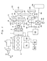
- FIG. 1 shows the layout of a power transmission device for a hybrid vehicle provided with a control device according to the present invention.
- This power transmission device is employed for ordinary running drive and is provided with an engine E capable of temporary stoppage control.
- a vacuum tank 6 is provided that accumulates negative pressure by extracting negative pressure from suction pipe 5 of this engine E; the negative pressure of vacuum tank 6 is supplied to brake booster 8, multiplying the operating force of brake pedal 8 in performing brake operation.
- the first motor generator 1 is provided on the output shaft Es of engine E; this first motor generator 1 performs starting drive of engine E and engine drive assistance etc when moving off, and also performs energy regeneration by being used as a generator during deceleration.
- the output shaft Es of engine E is coupled with forwards/reverse changeover mechanism 10 through a damper mechanism 2.
- a first hydraulic pump 3 is driven by engine E, this first hydraulic pump 3 being provided on this engine output shaft Es.
- Forwards/reverse changeover mechanism 10 comprises a single pinion type planetary gear having a sun gear 11 coupled with engine output shaft Es through dumper mechanism 2, a carrier 12 that freely rotatably supports the pinion gear arranged meshing therewith at the periphery of sun gear 11 and which is freely rotatably arranged coaxially with sun gear 11, and ring gear 13 that is freely rotatably arranged coaxially with sun gear 11, meshing with the pinion gear, and which is linked with the gear-change mechanism input shaft 21, and is further provided with a forwards clutch 14 capable of connecting and disconnecting carrier 12 and sun gear 11 (or engine output shaft Es), and a reverse brake 15 capable of fixing and holding carrier 12.
- a metal V belt type infinitely variable gear-change mechanism 20 is constructed having a gear-change mechanism input shaft 21; rotation of gear-change mechanism input shaft 21 which is driven in rotation as described above is subjected to an infinitely variable change in gear ratio by infinitely variable gear-change mechanism 20 and transmitted to gear-change mechanism output shaft 27.
- Infinitely variable gear-change mechanism 20 comprises a drive pulley 22 whose pulley width is capable of being variably adjusted by means of drive-side hydraulic cylinder 23, driven pulley 25 whose pulley width is capable of being variably adjusted by means of driven-side hydraulic cylinder 26, and a metal V belt 24 that is provided between the two pulleys 22 and 25.
- Drive pulley 22 is connected to gear-change mechanism input shaft 21 and driven pulley 25 is connected to gear-change mechanism output shaft 27. Consequently, rotation of gear-change mechanism input shaft 21 can be transmitted to gear-change mechanism output shaft 27 with an infinitely variable gear ratio, by controlling the hydraulic pressure that is supplied to the drive and driven side hydraulic cylinders 23 and 26.
- Moving-off clutch 30 is connected to gear-change mechanism output shaft 27.
- Moving-off clutch 30 comprises a clutch of the hydraulically actuated type and engagement control of moving-off clutch 30 is performed by control of the actuating hydraulic pressure.
- An idler shaft 31 that is coupled with a gear-change mechanism input shaft 27 through moving-off clutch 30 is freely rotatably arranged; a final drive gear 32 that is arranged coupled with idler shaft 31 meshes with a final driven gear 33 incorporating a differential mechanism 34.
- Differential mechanism 34 is coupled with the left and right vehicle wheels 36 through left and right axle shafts 34 (only the right hand ones are shown in the Figure).
- a motor-side driven gear 38 is arranged coupled with idler shaft 31 and meshes with motor-side drive gear 37 which is arranged coupled with the rotary shaft of a second motor generator 50. Consequently, the left and right vehicle wheels 36 can be driven from idler shaft 31 by means of second motor generator 50 and, contrariwise, using this as a generator, energy regeneration can be performed by this being rotated by receiving drive force from vehicle wheels 36.
- the first and second motor generators 3, 50 are connected to battery 51 through power drive unit 52. In this way, these motor generators 3, 50 can be driven by supplying power from battery 51, or the battery can be charged (i.e. energy regeneration performed) by the power obtained by making these motor generators 3, 50 act as generators when they are driven in rotation.
- an electric motor 55 for pump drive is connected to power drive unit 52 and a second hydraulic pump 56 is connected to the rotary drive shaft of this electric motor for pump drive 55.
- the second hydraulic pump 56 can therefore be driven by driving electric motor for pump drive 55 by the power from battery 51.
- the output of engine E or the output of first motor generator 1 is transmitted through forwards/reverse changeover mechanism 10 to infinitely variable gear-change mechanism 20, where the transmission ratio is changed, after which transmission control is performed by moving-off clutch 30 and, further, is transmitted to the left and right vehicle wheels 36 through differential mechanism 34 etc.
- vehicle running drive is performed by engine E or first motor generator 1.
- first motor generator 1 is driven in rotation by the vehicle wheels 36 as for example during decelerating running, this acts as a generator so that energy regeneration is thereby performed.
- the output of the second motor generator 50 is transmitted to the left and right vehicle wheels 36 through differential mechanism 34 etc from idler shaft 31. In this case also, when the second motor generator 50 is driven in rotation by vehicle wheels 36, this acts as a generator so that energy regeneration is performed.
- first rotation sensor 41 that detects rotation of the gear-change mechanism input shaft 21 (drive pulley 22)
- second rotation sensor 42 that detects rotation of the gear-change mechanism output shaft 27 (driven pulley 25)
- third rotation sensor 43 that detects rotation (i.e. vehicle speed) of the final driven gear 33.
- control actions are performed by using the hydraulic pressure supplied from first hydraulic pump 3 or second hydraulic pump 56.
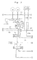
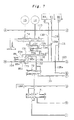
- the construction of the hydraulic control device that performs these control actions is described below with reference to the hydraulic circuit diagrams of Figure 2 to Figure 4 and the hydraulic circuit schematic view of Figure 5.
- the hydraulic circuits indicated by the circled letters of the alphabet A to I are mutually connected.
- This hydraulic control device comprises a first hydraulic pump 3 and second hydraulic pump 56 that deliver working hydraulic fluid in oil tank 60 formed by the gear-change mechanism housing etc.
- first hydraulic pump 3 is driven by engine E and second hydraulic pump 56 is driven by electric motor for pump drive 55.
- a relief valve 57 and one-way valve at 58 are provided on the discharge hydraulic fluid path of the second hydraulic pump 56 driven by electric motor for pump drive 55.
- a high hydraulic pressure for control purposes is created by adjusting the pressure of the hydraulic fluid discharged by the two hydraulic pumps 3, 56 by means of high pressure regulator valve 61, and this high hydraulic pressure for control purposes is supplied to a shift valve 65 and low-pressure regulator valve 64.
- a low hydraulic pressure for control purposes created by pressure adjustment by low-pressure regulator valve 64 is also supplied to shift valve 65.
- High-pressure regulator valve 61 creates a high hydraulic pressure for control purposes in accordance with the back pressure from high-pressure control valve 62 and the operation of high-pressure control valve 62 and low-pressure regulator valve 64 is controlled by the hydraulic pressure for control purposes from high/low pressure control valve 63.
- High/low pressure control valve 63 creates an arbitrary hydraulic pressure for control purposes in accordance with the control current by means of linear solenoid 63a; as can be understood from this, a high hydraulic pressure for control purposes and a low hydraulic pressure for control purposes are set by signal current control of linear solenoid 63a of the high/low-pressure control valve 63.
- Shift valve 65 supplies in distributed fashion high pressure hydraulic fluid for control purposes and low-pressure hydraulic fluid for control purposes supplied as described above to drive- and driven-side hydraulic cylinders 23 and 26 so as to effect gear ratio control by pulley width adjustment of the drive and driven pulleys 22 and 25.
- the operation of this shift valve 65 is controlled by shift control hydraulic pressure from a shift control valve 66 actuated by linear solenoid 66a.
- gear ratio control can be performed by controlling the operation of shift valve 65 by performing signal current control of linear solenoid 66a.
- the high hydraulic pressure for control purposes created by high pressure control valve 61 is supplied to clutch reducing valve 72 from hydraulic fluid path 101, creating line pressure, which line pressure is supplied to hydraulic fluid path 102.
- the excess hydraulic fluid that is evacuated from high-pressure regulator valve 61, high-pressure control valve 62, and clutch reducing valve 72 is adjusted in pressure by lubricating valve 71 and supplied to lubricating section LUBE.
- the line pressure of the hydraulic fluid path 102 is supplied from hydraulic fluid path 103 to high/low pressure control valve 63 and shift control valve 66 and furthermore is supplied from hydraulic fluid paths 104, 104a to a moving-off clutch control valve 75, to be described.
- the line pressure of hydraulic fluid path 102 is supplied through hydraulic fluid path 105 to high pressure control solenoid valve 82 and is supplied through hydraulic fluid path 105a to high pressure control valve 62.
- the line pressure of hydraulic fluid path 102 is further supplied from hydraulic fluid path 106 through forwards/reverse clutch control valve 73 to hydraulic fluid path 107 and furthermore is arranged to be selectively supplied through manual valve 74 to forward clutch 14 and reverse brake 15.
- Forwards/reverse clutch control valve 73 as shown in the Figure, is provided with four ports 73a to 73d, first port 73a being connected to hydraulic fluid path 106, second port 73b being connected to hydraulic fluid path 107, third port 73c being connected to hydraulic fluid path 121, and fourth port 73d being connected to hydraulic fluid path 108a.
- the action of the forwards/reverse clutch control valve 73 is controlled by forwards/reverse clutch control solenoid valve 81, so that control is effected whereby line pressure is supplied to forwards clutch 14 and reverse brake 15 through manual valve 74, or supply thereof is cut off. That is, this control is control that is performed under normal conditions; if abnormality occurs, as will be described, line pressure supply control from hydraulic fluid path 121 is performed.
- Manual valve 74 performs a changeover action in response to operation of the gear shift lever at the driver's seat whereby it blocks hydraulic fluid path 107 in ranges P and N and connects both the forward clutch 14 and reverse brake 15 to the drain, thereby releasing the forward clutch 14 and reverse brake 15.
- range R it connects reverse brake 15 with the hydraulic fluid path 107, so that line pressure is supplied to the reverse brake 15, which can thereby be engaged.
- the forward drive ranges i.e. D, S, and L ranges it connects hydraulic fluid path 107 with forward clutch 14, causing line pressure to be supplied to the forward clutch 14, which can thereby be engaged.
- moving-off clutch control valve 75 that is supplied with line pressure through hydraulic fluid paths 104, 104a is controlled by linear solenoid 75a, causing moving-off clutch control hydraulic pressure to be supplied to moving-off clutch 30 through shift inhibitor valve 77, thereby performing engagement control of moving-off clutch 30.
- the right-hand end of shift inhibitor valve 77 is connected to shift control valve 66 through hydraulic pressure path 110. If for example abnormality of the device occurs or supply of drive power disappears, the current passing through linear solenoid 66a of shift control valve 66 becomes zero, causing the shift control hydraulic pressure that is supplied to hydraulic fluid path 110 to be made the maximum.
- the Pitot pressure from Pitot control valve 78 is supplied to moving-off clutch 30 instead of the control hydraulic pressure from moving-off clutch control valve 75. That is, in the event of abnormality etc, it can be arranged for engagement control of moving-off clutch 30 to be performed using the Pitot pressure.
- This maximum control hydraulic pressure is also supplied to shift valve 65, causing its spool to be shifted to the right, so that high hydraulic pressure for control purposes is supplied to driven-side hydraulic pressure cylinder 26, and low hydraulic pressure for control purposes is supplied to drive-side hydraulic pressure cylinder 23, causing the gear ratio to be made LOW.
- hydraulic fluid path 121 is branched from hydraulic fluid path 122 and, as described above, hydraulic fluid path 121 is connected with third port 73c of forwards/reverse clutch control valve 73. Consequently, when, under abnormal conditions etc as described above, the spool of shift inhibitor valve 77 is moved to the left, line pressure is supplied from hydraulic fluid path 104b to hydraulic fluid path 122, whereupon line pressure is supplied to third port 73c of forwards/reverse clutch control valve 73 through hydraulic fluid path 121. It should be noted that, when the spool of shift inhibitor valve 77 is moved to the right under normal conditions, as can be seen from Figure 2, hydraulic fluid path 122 is put in communication with the drain, thereby allowing hydraulic fluid path 121 also to communicate with the drain.
- the shift inhibitor valve 77 corresponds to the first auxiliary changeover valve in the Claims, the rightwardly moved position of its spool being the ordinary position, while the leftwardly moved position is the fail position; the line pressure that is supplied to hydraulic fluid path 121 by leftwards movement of the spool is the fail control hydraulic pressure.
- shift control valve 66 corresponds to the first auxiliary operation control means.
- a power transmission device for a hybrid vehicle constructed as above basically, the driving force of engine E is changed in transmission ratio by means of forwards/reverse changeover mechanism 10 and infinitely variable gear-change mechanism 20 and effects running drive by being transmitted from moving-off clutch 30 to the vehicle wheels through final drive and driven gears 32 and 33, differential mechanism 34, and axle shafts 35 etc. That is, vehicle running is performed by drive of engine E.
- drive assistance is effected by means of first motor generator 1 and during deceleration energy regeneration is performed (battery 51 is charged) by operating first motor generator 1 as a generator.
- control is effected to temporarily stop the engine E with the aim of improving fuel consumption.
- control is exercised to continue running by driving vehicle wheels 36 by driving second motor generator 50.
- generation of entrainment torque on the engine side from forwards/reverse changeover mechanism 10 is prevented by releasing both forwards clutch 14 and reverse brake 15.
- Moving-off clutch 30 is put into a lightly engaged condition such as to transmit just the torque necessary for no-load rotary drive of infinitely variable gear-change mechanism 20; control is performed to set the gear ratio of the infinitely variable gear-change mechanism 20 to match the current driving conditions, by control of the hydraulic pressure supplied to the drive- and driven-side hydraulic pressure cylinders 23, 26 in the infinitely variable gear-change mechanism 20 that is thus performing no-load rotary drive.
- the shift control hydraulic pressure that is supplied to hydraulic fluid path 110 is made a maximum by making the current passed to shift control valve 66 zero.
- the maximum shift control hydraulic pressure therefore acts through hydraulic fluid path 110 on the right hand end of shift inhibitor valve 77, moving its spool to the left against the spring force, and putting the hydraulic fluid path 104b and hydraulic fluid path 122 in communication.
- line pressure from hydraulic fluid path 104b is supplied to hydraulic fluid path 121 from hydraulic fluid path 122 and is further supplied to forwards clutch 14 or reverse brake 15 through manual valve 74 from hydraulic fluid path 107.
- This control merely involves cutting off the supply of current to shift control valve 66, so this control can be performed without being affected by electrical abnormalities. Consequently, if abnormality is detected when running drive is performed by the second motor generator 50 on temporary stoppage of engine E and release of both forwards clutch 14 and reverse brake 15, a shift to drive running using the engine E can be reliably effected by engagement of forwards clutch 14 or reverse brake 15 without being affected by such abnormality, by cutting off passage of current to shift control valve 66 as described above.
- detection of whether or not abnormality has occurred such that running drive by the engine E has become impossible, with both the forwards clutch 14 and reverse brake 15 still released is performed by comparing the engine rotary speed and gear-change mechanism output rotary speed or vehicle speed, taking into account the gear ratio, when the gear shift lever is in a position other than P (parking) range or N (neutral) range, by ascertaining whether or not these are in rotational speed relationship when the forwards clutch 14 or reverse brake 15 is connected.
- this detection is not restricted to this and could be performed by detecting the hydraulic pressure actually acting on forwards clutch 14 and reverse brake 15.
- forwards/reverse clutch control valve 73 has four ports 73a to 73d, first port 73a being connected with hydraulic fluid path 106, second port 73b being connected with hydraulic fluid path 107, the third port 73c being connected with hydraulic fluid path 131, and fourth port 73d being connected with hydraulic fluid path 108a.
- Hydraulic fluid path 131 is connected to the second port 85b of an auxiliary changeover valve 85.
- This auxiliary changeover valve 85 comprises a first port 85a that is released to the drain, a second port 85b that is connected to hydraulic fluid path 131 as described above, a third port 85c connected to hydraulic fluid path 133, and a fourth port 85d connected to hydraulic fluid path 132.
- Hydraulic fluid path 133 is connected to hydraulic fluid path 106 so that line pressure is supplied to third port 85c.
- Hydraulic fluid path 132 is branched from hydraulic fluid path 103 and is connected to hydraulic fluid path 135 having an auxiliary changeover control solenoid valve 83, so that control is possible whereby line pressure is made act on the fourth port 85d by means of auxiliary changeover control solenoid valve 83.
- forwards/reverse clutch control valve 73 and auxiliary changeover valve 85 described above may be summarized as follows. First of all, in a condition in which the spool of forwards/reverse clutch control valve 73 has been moved to the left by action of line pressure in hydraulic fluid path 108a, when the spool of auxiliary changeover valve 85 is moved to the left by action of the line pressure in hydraulic fluid path 132, the line pressure from hydraulic fluid path 106 is supplied to hydraulic fluid path 107 through forwards/reverse clutch control valve 73, and is thus supplied to manual valve 74.
- moving-off clutch control valve 75 that is supplied with line pressure through hydraulic fluid paths 104, 104a is controlled by linear solenoid 75a, causing moving-off clutch control hydraulic pressure to be supplied to moving-off clutch 30 through shift inhibitor valve 77 so that engagement control of moving-off clutch 30 is performed.
- the right hand end of shift inhibitor valve 77 is connected to shift control valve in 66 through hydraulic fluid path 110. If for example device abnormality occurs or supply of drive electric power ceases, the current passed to linear solenoid 66a of shift control valve 66 becomes zero, causing the shift control hydraulic pressure that is supplied to hydraulic fluid path 110 to become a maximum.
- the control under these circumstances is the same as in the example described above, so further description of the operation is omitted.
- a power transmission device for a hybrid vehicle constructed as above basically, the driving force of engine E is changed in transmission ratio by means of forwards/reverse changeover mechanism 10 and infinitely variable gear-change mechanism 20 and effects running drive by being transmitted from moving-off clutch 30 to the vehicle wheels through final drive and driven gears 32 and 33, differential mechanism 34, and axle shafts 35 etc. That is, vehicle running is performed by drive of engine E.
- control is effected to temporarily stop the engine E.
- control is simultaneously exercised to continue running by driving vehicle wheels 36 by driving second motor generator 50.
- generation of entrainment torque on the engine side from forwards/reverse changeover mechanism 10 is prevented by releasing both forwards clutch 14 and reverse brake 15.
- Moving-off clutch 30 is put into a lightly engaged condition such as to transmit just the torque necessary for no-load rotary drive of infinitely variable gear-change mechanism 20; control is performed to set the gear ratio of the infinitely variable gear-change mechanism 20 to match the current driving conditions, by control of the hydraulic pressure supplied to the drive- and driven-side hydraulic pressure cylinders 23, 26 in the infinitely variable gear-change mechanism 20 that is thus performing no-load rotary drive.
- auxiliary changeover valve 85 corresponds to the second auxiliary changeover valve in the Claims and the position in which its spool is moved to the right is the drain position while the position in which this is moved to the left is the supply position.
- auxiliary changeover solenoid valve 83 corresponds to the second means for auxiliary operation control.
- a forwards/reverse changeover mechanism 10 is released by a forwards/reverse clutch control valve 73.
- a gear shift inhibitor valve 77 is operated by a gear shift control valve 66 to supply line pressure to the forwards/reverse changeover mechanism 10 through a port of the forwards/reverse clutch control valve 73 in this sticking condition, so that this can thereby be engaged.
Landscapes
- Engineering & Computer Science (AREA)
- Chemical & Material Sciences (AREA)
- Combustion & Propulsion (AREA)
- Mechanical Engineering (AREA)
- Transportation (AREA)
- Automation & Control Theory (AREA)
- General Engineering & Computer Science (AREA)
- Physics & Mathematics (AREA)
- Fluid Mechanics (AREA)
- Control Of Transmission Device (AREA)
- Control Of Vehicle Engines Or Engines For Specific Uses (AREA)
- Hybrid Electric Vehicles (AREA)
Applications Claiming Priority (6)
| Application Number | Priority Date | Filing Date | Title |
|---|---|---|---|
| JP2000007339A JP3550067B2 (ja) | 2000-01-17 | 2000-01-17 | ハイブリッド車両の制御装置 |
| JP2000007339 | 2000-01-17 | ||
| JP2000014406 | 2000-01-24 | ||
| JP2000014406A JP3550068B2 (ja) | 2000-01-24 | 2000-01-24 | ハイブリッド車両の制御装置 |
| JP2000015437A JP3592982B2 (ja) | 2000-01-25 | 2000-01-25 | ハイブリッド車両の制御装置 |
| JP2000015437 | 2000-01-25 |
Publications (3)
| Publication Number | Publication Date |
|---|---|
| EP1116620A2 true EP1116620A2 (de) | 2001-07-18 |
| EP1116620A3 EP1116620A3 (de) | 2005-08-31 |
| EP1116620B1 EP1116620B1 (de) | 2006-06-28 |
Family
ID=27342058
Family Applications (1)
| Application Number | Title | Priority Date | Filing Date |
|---|---|---|---|
| EP01100392A Expired - Lifetime EP1116620B1 (de) | 2000-01-17 | 2001-01-05 | Steuerungsvorrichtung eines Hybridfahrzeugs |
Country Status (2)
| Country | Link |
|---|---|
| EP (1) | EP1116620B1 (de) |
| DE (1) | DE60121067T2 (de) |
Cited By (8)
| Publication number | Priority date | Publication date | Assignee | Title |
|---|---|---|---|---|
| CN101363534A (zh) * | 2007-08-07 | 2009-02-11 | 现代自动车株式会社 | 用于无级变速器的冷却装置 |
| WO2008111541A3 (en) * | 2007-03-09 | 2009-02-26 | Toyota Motor Co Ltd | Control device for vehicular drive system |
| WO2009074136A3 (de) * | 2007-12-10 | 2009-10-15 | Luk Lamellen Und Kupplungsbau Beteiligungs Kg | Hydraulikversorgungssystem für ein hydraulisch betätigtes, automatisches getriebe |
| US8733209B2 (en) | 2007-02-26 | 2014-05-27 | Ulrich Rohs | Drive arrangement with an infinitely variable sub-gear box |
| CN113212760A (zh) * | 2021-03-31 | 2021-08-06 | 成都飞机工业(集团)有限责任公司 | 一种用于高空探测的气象探空吊舱运转异常处置方法 |
| US20220063596A1 (en) * | 2019-02-06 | 2022-03-03 | Aisin Corporation | Control device for vehicle drive device |
| CN114165581A (zh) * | 2021-11-04 | 2022-03-11 | 潍柴动力股份有限公司 | 一种amt变速箱的换挡方法、装置、存储介质及终端 |
| CN114165580A (zh) * | 2021-11-04 | 2022-03-11 | 潍柴动力股份有限公司 | 一种amt变速箱的换挡方法、装置、存储介质及终端 |
Citations (2)
| Publication number | Priority date | Publication date | Assignee | Title |
|---|---|---|---|---|
| JPH11132321A (ja) | 1997-10-29 | 1999-05-21 | Nissan Motor Co Ltd | エンジン自動停止車両の油圧制御装置 |
| JP2000015437A (ja) | 1998-06-26 | 2000-01-18 | Toshiba Corp | 管端自動シール溶接機 |
Family Cites Families (2)
| Publication number | Priority date | Publication date | Assignee | Title |
|---|---|---|---|---|
| BR8707683A (pt) * | 1986-05-02 | 1989-08-15 | Zahnradfabrik Friedrichshafen | Comando eletro-hidraulico |
| JP3721661B2 (ja) * | 1996-10-23 | 2005-11-30 | アイシン精機株式会社 | 自動変速機の油圧制御装置 |
-
2001
- 2001-01-05 DE DE60121067T patent/DE60121067T2/de not_active Expired - Fee Related
- 2001-01-05 EP EP01100392A patent/EP1116620B1/de not_active Expired - Lifetime
Patent Citations (2)
| Publication number | Priority date | Publication date | Assignee | Title |
|---|---|---|---|---|
| JPH11132321A (ja) | 1997-10-29 | 1999-05-21 | Nissan Motor Co Ltd | エンジン自動停止車両の油圧制御装置 |
| JP2000015437A (ja) | 1998-06-26 | 2000-01-18 | Toshiba Corp | 管端自動シール溶接機 |
Cited By (12)
| Publication number | Priority date | Publication date | Assignee | Title |
|---|---|---|---|---|
| US8733209B2 (en) | 2007-02-26 | 2014-05-27 | Ulrich Rohs | Drive arrangement with an infinitely variable sub-gear box |
| WO2008111541A3 (en) * | 2007-03-09 | 2009-02-26 | Toyota Motor Co Ltd | Control device for vehicular drive system |
| US8696516B2 (en) | 2007-03-09 | 2014-04-15 | Toyota Jidosha Kabushiki Kaisha | Control device for vehicular drive system |
| CN101363534A (zh) * | 2007-08-07 | 2009-02-11 | 现代自动车株式会社 | 用于无级变速器的冷却装置 |
| WO2009074136A3 (de) * | 2007-12-10 | 2009-10-15 | Luk Lamellen Und Kupplungsbau Beteiligungs Kg | Hydraulikversorgungssystem für ein hydraulisch betätigtes, automatisches getriebe |
| US8353805B2 (en) | 2007-12-10 | 2013-01-15 | Schaeffler Technologies AG & Co. KG | Hydraulic supply system for a hydraulically actuated automatic transmission |
| US20220063596A1 (en) * | 2019-02-06 | 2022-03-03 | Aisin Corporation | Control device for vehicle drive device |
| US11981322B2 (en) * | 2019-02-06 | 2024-05-14 | Aisin Corporation | Control device for vehicle drive device |
| CN113212760A (zh) * | 2021-03-31 | 2021-08-06 | 成都飞机工业(集团)有限责任公司 | 一种用于高空探测的气象探空吊舱运转异常处置方法 |
| CN113212760B (zh) * | 2021-03-31 | 2022-01-25 | 成都飞机工业(集团)有限责任公司 | 一种用于高空探测的气象探空吊舱运转异常处置方法 |
| CN114165581A (zh) * | 2021-11-04 | 2022-03-11 | 潍柴动力股份有限公司 | 一种amt变速箱的换挡方法、装置、存储介质及终端 |
| CN114165580A (zh) * | 2021-11-04 | 2022-03-11 | 潍柴动力股份有限公司 | 一种amt变速箱的换挡方法、装置、存储介质及终端 |
Also Published As
| Publication number | Publication date |
|---|---|
| EP1116620A3 (de) | 2005-08-31 |
| DE60121067D1 (de) | 2006-08-10 |
| DE60121067T2 (de) | 2006-11-16 |
| EP1116620B1 (de) | 2006-06-28 |
Similar Documents
| Publication | Publication Date | Title |
|---|---|---|
| US6554736B2 (en) | Hybrid vehicle control device | |
| US6638022B2 (en) | Hybrid vehicle control device | |
| EP2797766B1 (de) | Antriebssystem und elektrisches fahrzeug damit | |
| US6543311B1 (en) | Driving system for industrial trucks | |
| JP2001065684A (ja) | ベルト式無段変速機の油圧回路 | |
| US9975553B2 (en) | Automatic transmission | |
| KR20180106981A (ko) | 감속 기반 브레이크 냉각제 시스템 및 그 방법 | |
| EP1116620B1 (de) | Steuerungsvorrichtung eines Hybridfahrzeugs | |
| JP4060537B2 (ja) | 車輌の補助ブレーキシステム | |
| JP2005155729A (ja) | ベルト式無段変速機の油圧制御装置 | |
| US7074148B2 (en) | Hydraulic controller of power transmission device | |
| JP4014687B2 (ja) | 自動変速機用油圧制御装置 | |
| JP2014052034A (ja) | 自動変速機の油圧制御装置 | |
| US20220089013A1 (en) | Vehicle drive device | |
| JP6561601B2 (ja) | 作業車両 | |
| JPH09105457A (ja) | 無段変速機の制御装置 | |
| JP2009115116A (ja) | 車両用自動変速機の油圧制御装置 | |
| JP2011052795A (ja) | 車両用伝動機構の油圧制御装置 | |
| JP3521684B2 (ja) | パワーテイクオフ装置付自動変速機 | |
| JP3602276B2 (ja) | 無段変速装置の油圧制御回路 | |
| JP6795055B2 (ja) | 作業車両の走行伝動装置 | |
| JP2005163869A (ja) | ベルト式無段変速機の油圧制御装置 | |
| JP2570035B2 (ja) | 無段変速機の変速比制御装置 | |
| JPS607133B2 (ja) | 車両用自動変速機 | |
| JP2781230B2 (ja) | 無段変速機の油圧制御装置 |
Legal Events
| Date | Code | Title | Description |
|---|---|---|---|
| PUAI | Public reference made under article 153(3) epc to a published international application that has entered the european phase |
Free format text: ORIGINAL CODE: 0009012 |
|
| AK | Designated contracting states |
Kind code of ref document: A2 Designated state(s): AT BE CH CY DE DK ES FI FR GB GR IE IT LI LU MC NL PT SE TR |
|
| AX | Request for extension of the european patent |
Free format text: AL;LT;LV;MK;RO;SI |
|
| PUAL | Search report despatched |
Free format text: ORIGINAL CODE: 0009013 |
|
| AK | Designated contracting states |
Kind code of ref document: A3 Designated state(s): AT BE CH CY DE DK ES FI FR GB GR IE IT LI LU MC NL PT SE TR |
|
| AX | Request for extension of the european patent |
Extension state: AL LT LV MK RO SI |
|
| 17P | Request for examination filed |
Effective date: 20050823 |
|
| GRAP | Despatch of communication of intention to grant a patent |
Free format text: ORIGINAL CODE: EPIDOSNIGR1 |
|
| RIC1 | Information provided on ipc code assigned before grant |
Ipc: B60K 6/04 20060101AFI20051220BHEP |
|
| GRAS | Grant fee paid |
Free format text: ORIGINAL CODE: EPIDOSNIGR3 |
|
| AKX | Designation fees paid |
Designated state(s): DE GB |
|
| GRAA | (expected) grant |
Free format text: ORIGINAL CODE: 0009210 |
|
| AK | Designated contracting states |
Kind code of ref document: B1 Designated state(s): DE GB |
|
| REG | Reference to a national code |
Ref country code: GB Ref legal event code: FG4D |
|
| REF | Corresponds to: |
Ref document number: 60121067 Country of ref document: DE Date of ref document: 20060810 Kind code of ref document: P |
|
| PLBE | No opposition filed within time limit |
Free format text: ORIGINAL CODE: 0009261 |
|
| STAA | Information on the status of an ep patent application or granted ep patent |
Free format text: STATUS: NO OPPOSITION FILED WITHIN TIME LIMIT |
|
| 26N | No opposition filed |
Effective date: 20070329 |
|
| PGFP | Annual fee paid to national office [announced via postgrant information from national office to epo] |
Ref country code: DE Payment date: 20080104 Year of fee payment: 8 Ref country code: GB Payment date: 20080102 Year of fee payment: 8 |
|
| GBPC | Gb: european patent ceased through non-payment of renewal fee |
Effective date: 20090105 |
|
| PG25 | Lapsed in a contracting state [announced via postgrant information from national office to epo] |
Ref country code: DE Free format text: LAPSE BECAUSE OF NON-PAYMENT OF DUE FEES Effective date: 20090801 |
|
| PG25 | Lapsed in a contracting state [announced via postgrant information from national office to epo] |
Ref country code: GB Free format text: LAPSE BECAUSE OF NON-PAYMENT OF DUE FEES Effective date: 20090105 |