EP1116680B1 - Spulmaschine - Google Patents
Spulmaschine Download PDFInfo
- Publication number
- EP1116680B1 EP1116680B1 EP01100485A EP01100485A EP1116680B1 EP 1116680 B1 EP1116680 B1 EP 1116680B1 EP 01100485 A EP01100485 A EP 01100485A EP 01100485 A EP01100485 A EP 01100485A EP 1116680 B1 EP1116680 B1 EP 1116680B1
- Authority
- EP
- European Patent Office
- Prior art keywords
- guide
- thread
- traversing
- housing
- winding machine
- Prior art date
- Legal status (The legal status is an assumption and is not a legal conclusion. Google has not performed a legal analysis and makes no representation as to the accuracy of the status listed.)
- Expired - Lifetime
Links
Images


Classifications
-
- B—PERFORMING OPERATIONS; TRANSPORTING
- B65—CONVEYING; PACKING; STORING; HANDLING THIN OR FILAMENTARY MATERIAL
- B65H—HANDLING THIN OR FILAMENTARY MATERIAL, e.g. SHEETS, WEBS, CABLES
- B65H54/00—Winding, coiling, or depositing filamentary material
- B65H54/02—Winding and traversing material on to reels, bobbins, tubes, or like package cores or formers
- B65H54/28—Traversing devices; Package-shaping arrangements
- B65H54/2806—Traversing devices driven by cam
- B65H54/2809—Traversing devices driven by cam rotating grooved cam
- B65H54/2812—Traversing devices driven by cam rotating grooved cam with a traversing guide running in the groove
-
- B—PERFORMING OPERATIONS; TRANSPORTING
- B65—CONVEYING; PACKING; STORING; HANDLING THIN OR FILAMENTARY MATERIAL
- B65H—HANDLING THIN OR FILAMENTARY MATERIAL, e.g. SHEETS, WEBS, CABLES
- B65H2407/00—Means not provided for in groups B65H2220/00 – B65H2406/00 specially adapted for particular purposes
- B65H2407/50—Means for protecting parts of handling machine
- B65H2407/51—Means for making dustproof
-
- B—PERFORMING OPERATIONS; TRANSPORTING
- B65—CONVEYING; PACKING; STORING; HANDLING THIN OR FILAMENTARY MATERIAL
- B65H—HANDLING THIN OR FILAMENTARY MATERIAL, e.g. SHEETS, WEBS, CABLES
- B65H2701/00—Handled material; Storage means
- B65H2701/30—Handled filamentary material
- B65H2701/31—Textiles threads or artificial strands of filaments
Definitions
- the invention relates to a winding machine with a thread laying device.
- the thread laying device has a housing, in which a drivable having an endless thread groove Reverse thread shaft is rotatably mounted.
- a traverse guide has a basic body, one in the thread groove of the reverse thread shaft engaging boat and a thread guide.
- the traverse thread guide is axial due to the reverse thread shaft Direction reciprocally driven, the housing a has slot-shaped opening through which the thread guide of the Traversing thread guide from the housing of the thread laying device protrudes.
- Such a winding machine is preferably around a winding machine for winding a continuously thread running onto a bobbin. However, it can also be another design of a winding machine.
- a winding machine of the type described in the opening paragraph is known from DE 195 36 761 A1 .
- the bobbin winder has a thread laying device with a housing, in which a drivable reversible thread shaft having an endless thread groove is rotatably mounted.
- a traversing thread guide has a base body, a shuttle engaging in the thread groove of the reversing thread shaft and a thread guide. The traversing thread guide is driven back and forth in the axial direction by the reversing thread shaft, and the housing has a slot-shaped opening through which the thread guide of the traversing thread guide protrudes from the housing.
- the traversing thread guide For the radial guidance of the traversing thread guide, its base body is connected to two spaced guide rods 5 which extend parallel to the axis of the reversing thread shaft, the base body having two circular bores through which the cylindrical guide rods extend.
- the guide rods extend over the entire length of the reverse thread shaft or the area of the reverse thread shaft in which the endless thread groove is present.
- the guide rods must run exactly parallel.
- the separate guide rods must be manufactured, hardened and ground precisely. When installing the guide rods, make sure that they are aligned exactly.
- the winding machine has a thread laying device with a housing, a reversing thread shaft and a traversing thread guide.
- Two parallel guide rails are provided on the housing and are in contact with the base body of the traversing thread guide in such a way that it is guided radially.
- the guide rails must be manufactured separately, hardened and ground in the contact area with the base body of the traversing thread guide.
- the guide rails are then screwed to the housing, for which purpose a corresponding milling is attached to the housing. The milling causes a structural weakening of the housing.
- the processing of the guide rails is relatively complex and expensive.
- the traversing thread guide points a base body that turns as a circumferentially the axis of the reverse thread shaft extending by about 90 ° forms.
- the slider is on its inside and provided with sliding surfaces on the outside and between the outer circumference of the reverse screw shaft and one the reverse screw shaft with a surrounding tube slidably mounted.
- the Pipe prevents the slider from radially outward the reverse thread shaft removed.
- three parts are used accordingly must be elaborately machined and assembled so that a sliding guide for the traverse guide.
- DE 959 534 C describes a thread guide device for a Known winding machine. It is a powered reverse thread shaft provided by a sleeve-like or bush-like bearing part is surrounded on its entire circumference. There is a on the bearing part rotatable mandrel and the thread guide provided. The thread guide is arranged on the bearing part to be movable in the reversal points of the coil an axial movement between the To allow thread guides and the bearing part. It is not recognizable whether and how the thread guide is guided on the bearing part or is held or by what measures a leadership of the Thread guide is reached. Also the assignment and placement the reverse thread shaft and the thread guide in one housing not shown.
- a winch is known from US Pat. No. 3,980,252 Laying device is provided.
- the laying device has a driven reverse thread shaft with an endless thread groove.
- the reverse thread shaft is freely supported, i.e. without a housing and surrounded by the main body of a rope guide, who does so serves to absorb considerable forces of the wire rope and this to be placed next to one another on a drum in turns.
- the rope guide is provided with three roles, which in the endless Engage the thread groove.
- the main body of the rope guide is open the outside of the reversible thread shaft mounted and thus held radially. Another role on the rope guide engages between two guide rods.
- the invention has for its object to provide a winder to provide a thread laying device in which the radial guiding of the traversing thread guide inexpensively and with few components is realized.
- the radial guide of the traversing thread guide with the thread guide no longer outside the Housing or in the region of the slot-shaped opening of the Housing, but inside the housing on the reverse screw shaft realized.
- the outer peripheral surface of the reverse thread shaft is at least partially from the inner peripheral surface of the Enclosed guide bushing of the traversing thread guide, the Enclosure is greater than 180 ° to secure the radial Ensure traversing thread guide.
- More separate Guide elements, such as guide rods or guide rails, are not required. This increases the number of components advantageously reduced. Because the reverse thread shaft for contact to the shuttle of the traversing thread guide mostly anyway is ground, is for the new function of the radial guide the traversing thread guide on the reverse thread shaft is no additional Processing step required.
- the traversing thread guide and the reverse thread shaft Sliding fit is also the inner peripheral surface of the guide bush ground.
- the guide bush preferably extends only over a small axial area of the reverse thread shaft, so that the surface of the guide bush to be machined is also low. This makes the grinding process inner peripheral surface of the guide bushing is little time-consuming and very inexpensive.
- the processing of the housing is advantageously simplified because of Area of the slot-shaped opening, the radial mounting of the Traversing thread guide does not have to provide.
- the stability of the Housing is improved because less material is used for the housing Attachment of, for example, guide rails can be removed got to.
- the inner peripheral surface of the guide bush and the outer Circumferential surface of the reverse thread shaft form a relatively large one Contact surface for radial guiding of the traversing thread guide, which reduces wear on the traversing thread guide becomes.
- the guide bushing can be closed in a circular shape his. This means that the guide bush in connection with the Basic body of the traversing thread guide the entire scope of Reverse thread shaft encloses. This has the advantage that a secure radial guidance of the traversing thread guide on the Circumferential surface of the reverse thread shaft is guaranteed.
- the guide bush or the base body the traversing thread guide has a bore into which the boat is inserted so that it is free in the hole is rotatable. The rotatability of the boat must be guaranteed so that there is no destruction of the boat Driving through the reversal points of the thread groove of the reverse thread shaft can come.
- the guide bushing can also partially extend along its circumference be open.
- the guide bush must do this be closed at least so far that they are in the radial direction is not removable from the reverse thread shaft, so that the radial Securing the traversing thread guide is always guaranteed.
- the not completely closed Training the guide bush has the advantage that the mass or the weight of the guide bush and the entire traversing thread guide is reduced.
- the inner surface to be machined the guide bush is smaller than that of a closed one Guide bushing, which increases the grinding effort further reduced. It is to reduce the mass of the guide bush also possible to make radial bores or the like in this.
- the reverse thread shaft can have a plurality of endless thread grooves have, each with a traversing thread guide is drivable.
- the thread grooves are axially spaced, so that the traversing thread guide is spaced axially move.
- the traversing thread guides can do this be inserted in the thread grooves that they are always in move the same distance from each other.
- the traverse guide can also be moved out of phase with each other.
- Two thread guides arranged offset by 180 ° can be provided his.
- the housing then has two 180 ° offset slit-shaped openings. That way you can Two thread guides are used to separate the thread on two Wind up spools.
- the traversing thread guide can have a cover that is under Formation of an air gap is connected to the base body, with a sealing tape for sealing the slit-shaped Opening of the housing extends through the air gap.
- a sealing tape for sealing the slit-shaped Opening of the housing extends through the air gap.
- the energy consumption of the Dishwasher rises with that caused by the pollution increasing friction. There is a risk that the traverse guide gets stuck and damaged in these dirt particles becomes. For example, cause such pollution a destruction of the traversing guide's boat.
- the new type of sealing effectively prevents the ingress of Impurities in the area of the reverse thread shaft.
- the new way of sealing the thread laying device the winder is also without using the Guide bush for the radial guidance of the traversing thread guide from great advantage.
- the sealing tape with its Both ends are firmly connected to the housing, this seals the slot-shaped opening of the housing effectively.
- the housing points to the area of the slot-shaped opening Walls a flat milling on which the sealing tape rests on the area of the traversing thread guide.
- the traversing thread guide itself Sealing the slot-shaped opening of the housing takes over.
- the axial movement of the traversing thread guide thus slides this along the stationary sealing tape, one Relative movement between the sealing tape and the air gap takes place, d. H. the traversing thread guide moves with his Cover over the sealing tape.
- the hold-down devices are used to hold down the sealing tape outside the Area of the traversing thread guide and also prevent this Penetration of dirt in the traversing thread guide and in the Reverse thread shaft area.
- the sealing tape is in one piece trained and has a length which is approximately the length of corresponds to the slot-shaped opening of the housing, with the Dimensioning and fastening of the sealing tape must be taken into account is that a certain length allowance for the radial too overcoming distance between the contact surface of the sealing tape and the air gap must be taken into account.
- the necessary length of the sealing tape is also from its Material or its elasticity dependent.
- that is Sealing tape designed as a hardened and ground steel tape.
- This has the advantage that the sealing tape is a good one Dimensional stability with low friction and minimal wear having.
- the sealing tape could be from another suitable material, for example a plastic fabric included glass fiber threads.
- the goal is always low friction, low wear, sufficient shape stability and to achieve flexibility of the sealing tape.
- the width of the air gap is preferably only slightly larger than the thickness of the sealing tape.
- the thickness of the sealing tape can be, for example, 0.5 mm. When installing the sealing tape this is biased so that a complete Support on the housing is guaranteed.
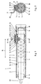
- FIG. 1 shows a longitudinal section through part of a winder 1 with a thread laying device 2. Only the components of winder 1 that are essential to the invention are shown.
- the thread laying device 2 has a housing 3 in which a drivable reversing thread shaft 5, which has an endless thread groove 4, is rotatably mounted.
- the drive of the reverse thread shaft 5 is implemented in the usual way and is therefore not shown.
- the winding machine 1 also has a traversing thread guide 6 with a base body 7, a shuttle 8 engaging in the thread groove 4 of the reversing thread shaft 5 and a thread guide 9.
- the traversing thread guide 6 can be driven translationally back and forth in the area of the thread groove 4 by the rotating reversing thread shaft 5 in the axial direction according to double arrow 10.
- the housing 3 has in its upper region a slot-shaped opening 11 through which the thread guide 9 and further parts of the traversing thread guide 6 protrude from the housing 3 in order to be able to come into contact with the thread 36 (FIG. 12).
- the traversing thread guide 6 has a guide bush 12 for radially guiding the traversing thread guide 6 relative to the housing 3, the inner circumferential surface 13 of which surrounds the outer circumferential surface 14 of the reversing thread shaft 5.
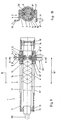
- Fig. 2 shows that the guide bush 12 is formed in an annular form closed in this embodiment.
- the inner circumferential surface 13 of the guide bush 12 and the outer circumferential surface 14 of the reversing thread shaft 5 are ground and together form a sliding fit.
- the reverse thread shaft 5 is with bearings 15, 16 and axial locking rings 17, 18 rotatably mounted inside the housing 3 and designed so that it with a rotary drive (not shown) is connectable.
- the endless thread groove 4 is attached on a larger diameter the Reverse thread shaft 5, the endless thread groove 4 is attached.
- the shuttle 8 of the traversing thread guide 6 thus engages in the thread groove 4 of the reverse thread shaft 5 that due to the geometry the thread groove 4 a rotary movement of the reverse thread shaft 5 in a translational movement of the traversing thread guide 6 in axial direction according to double arrow 10 is implemented.
- the traversing thread guide 6 in the radial direction i.e. perpendicular to the axis 28 through which Contact of the inner peripheral surface 13 of the guide bush 12 with the outer peripheral surface 14 of the reverse screw shaft 5 secured.
- the traversing thread guide 6 has a cover 19, which is below Formation of an air gap 20 with the base body 7 of the traversing thread guide 6 is firmly connected.
- a flat, elongated one Sealing tape 21 extends in the axial direction of the housing 3 of the thread laying device 2 along the slit-shaped Opening 11 and through the air gap 20 that the inside of the Housing 3 against the penetration of thread abrasion, dirt, dust, Contamination or the like is preserved.
- the sealing tape 21 is with its two axial ends 22, 23 by means of screws 24, 25 firmly connected to the housing.
- the housing 3 faces in the area the boundary of the opening 11 on a flat milling on which Sealing tape 21 lies flat.
- the sealing tape 21 has one greater width than the opening 11 so that it is complete is closed.
- the sealing tape 21 is hardened and ground Steel band formed so that the relative movement between the traversing thread guide 6 and the sealing tape 21 and the Sliding the sealing tape 21 through the air gap 20 low There is friction and little wear.
- Fig. 2 also shows that the boat 8 on the one hand on the bottom of the thread groove 4 of the reverse thread shaft 5 and on the other hand loosely in a central bore in the base body 7 of the traversing thread guide 6 is inserted.
- the lid 19 is fixed but detachable with the base body 7 of the traversing thread guide 6 connected. The connection is preferably through a Fitting made.
- the lid 19 is in turn with the Thread guide 9 firmly connected, the eyelet 29 for guiding the Thread 36 has.
- FIGS. 3 and 4 show a second embodiment of the bobbin winder 1 with a somewhat different embodiment of the thread laying device 2.
- the thread laying device 2 according to FIGS. 3 and 4 has two axially spaced areas in the region of its reversing thread shaft 5 Thread grooves 4, 4 'in which two separate traversing thread guides 6, 6' are guided to and fro. Accordingly, two separate openings 11, 11 'and two separate sealing tapes 21, 21' are also provided. With this arrangement, two traversing thread guides 6, 6 'can be driven simultaneously by means of only one reversing thread shaft 5.
- Fig. 3 shows an in-phase movement of the traversing thread guides 6, 6 '.
- FIG. 5 and 6 show a third embodiment of the winder 1 with the thread laying device 2.
- the thread laying device 2 again has a slit-shaped opening 11, which, however, is not closed by means of a sealing tape.
- the housing 3 was not sealed, ie the new type of radial securing of the traversing thread guide 6 was realized without the new type of sealing the opening 11 of the housing 3 of the thread laying device 2. Accordingly, the traversing thread guide 6 does not require a cover or an air gap formed thereon.
- FIG. 7 and 8 show a further embodiment of the winding machine 1 with the thread laying device 2, in which case the traversing thread guide 6 has two basic bodies 7, 7 ′′ arranged offset by 180 °, two boats 8, 8 ′′ and two thread guides 9, 9 ′. 'which protrude from the housing 3 of the thread laying device 2 through the two slot-shaped openings 11, 11''which are also arranged at 180 °. Accordingly, the housing 3 is sealed in the range of movement of the second thread guide 9 ′′ by means of a sealing tape 21 ′′, which is firmly connected to the housing 3 by screws 24 ′′, 25 ′′. Instead of the eyelet 29, the thread guide 9 ′′ here has two rollers 30, 30 ′′, between which the thread 36 runs. Other designs of the thread guide 9 or 9 ′′ are also conceivable.
- Fig. 8 shows that the shuttle 8 '' is identical to the shuttle 8 offset by 180 ° and engages with its one free end in the thread groove 4 of the reversible thread shaft 5.
- FIGS. 9 and 10 show a similar embodiment of the winding machine 1 and the thread laying device 2 as FIGS. 7 and 8, wherein in this example the housing 3 was also not sealed by means of a cover, an air gap and a sealing tape.
- FIG. 11 shows a detailed view of part of the traversing thread guide 6 of the winding machine 1.
- the hold-down devices 26, 27 of the traversing thread guide 6 serve to press the sealing tape 21 (FIG. 1) in the direction of the slit-shaped opening 11 (FIG. 1) in such a way that the penetration of contaminants and foreign bodies into the area of the housing 3 (FIG. 1) and the thread groove 4 of the reverse thread shaft 5 of the thread laying device 2 of the winding machine 1 is prevented.
- FIG. 12 shows a schematic overview view of the essential parts of the winding machine 1 with the thread laying device 2.
- the winding machine 1 has a base plate 31 with an elongated slot 32 therein, along the circular axis of which a winding spindle 33 with a sleeve 34 arranged thereon is guided.
- the thread 36 to be wound onto the sleeve 34 to form a bobbin 35 runs through the winding path 6 by means of the traversing thread guide 6 and is wound onto the sleeve 34 with the help of a pressure roller 37.
Landscapes
- Winding Filamentary Materials (AREA)
- Washing And Drying Of Tableware (AREA)
- Replacing, Conveying, And Pick-Finding For Filamentary Materials (AREA)
Description
- Fig. 1
- zeigt eine Schnittdarstellung einer ersten Ausführungsform einer Spulmaschine mit Fadenverlegevorrichtung.
- Fig. 2
- zeigt einen Schnitt entlang Linie II-II der Fadenverlegevorrichtung gemäß Fig. 1.
- Fig. 3
- zeigt eine Schnittdarstellung einer zweiten Ausführungsform der Spulmaschine mit Fadenverlegevorrichtung.
- Fig. 4
- zeigt einen Schnitt entlang Linie IV-IV der Fadenverlegevorrichtung gemäß Fig. 3.
- Fig. 5
- zeigt eine Schnittdarstellung einer dritten Ausführungsform der Spulmaschine mit Fadenverlegevorrichtung.
- Fig. 6
- zeigt einen Schnitt entlang Linie VI-VI der Fadenverlegevorrichtung gemäß Fig. 5.
- Fig. 7
- zeigt eine Schnittdarstellung einer weiteren Ausführungsform der Spulmaschine mit Fadenverlegevorrichtung.
- Fig. 8
- zeigt einen Schnitt entlang Linie VIII-VIII der Fadenverlegevorrichtung gemäß Fig. 7.
- Fig. 9
- zeigt eine Schnittdarstellung einer weiteren Ausführungsform der Spulmaschine mit Fadenverlegevorrichtung.
- Fig. 10
- zeigt einen Schnitt entlang Linie X-X der Fadenverlegevorrichtung gemäß Fig. 9.
- Fig. 11
- zeigt eine detallierte Schnittdarstellung des Changierfadenführers.
- Fig. 12
- zeigt eine schematisierte Übersichtsansicht der Spulmaschine mit Fadenverlegevorrichtung.
- 01
- Spulmaschine
- 02
- Fadenverlegevorrichtung
- 03
- Gehäuse
- 04
- Gewindenut
- 05
- Kehrgewindewelle
- 06
- Changierfadenführer
- 07
- Grundkörper
- 08
- Schiffchen
- 09
- Fadenführer
- 10
- Doppelpfeil
- 11
- Öffnung
- 12
- Führungsbuchse
- 13
- Innere Umfangsfläche
- 14
- Äußere Umfangsfläche
- 15
- Lager
- 16
- Lager
- 17
- Sicherungsring
- 18
- Sicherungsring
- 19
- Deckel
- 20
- Luftspalt
- 21
- Dichtungsband
- 22
- Ende
- 23
- Ende
- 24
- Schraube
- 25
- Schraube
- 26
- Niederhalter
- 27
- Niederhalter
- 28
- Achse
- 29
- Öse
- 30
- Rolle
- 31
- Grundplatte
- 32
- Langlochschlitz
- 33
- Spulspindel
- 34
- Hülse
- 35
- Spule
- 36
- Faden
- 37
- Andruckwalze
Claims (10)
- Spulmaschine (1) mit einer Fadenverlegevorrichtung (2) mit einem Gehäuse (3), einer in dem Gehäuse (3) drehbar gelagerten, eine endlose Gewindenut (4) aufweisenden antreibbaren Kehrgewindewelle (5) und einem Changierfadenführer (6) mit einem Grundkörper (7), einem in die Gewindenut (4) der Kehrgewindewelle (5) eingreifenden Schiffchen (8) und einem Fadenführer (9), wobei der Changierfadenführer (6) durch die Kehrgewindewelle (5) in axialer Richtung hin- und hergehend antreibbar ist und wobei das Gehäuse (3) eine schlitzförmige Öffnung (11) aufweist, durch die der Fadenführer (9) des Changierfadenführers (6) aus dem Gehäuse (3) herausragt, dadurch gekennzeichnet, dass der Changierfadenführer (6) eine Führungsbuchse (12) zur radialen Führung des Changierfadenführers (6) aufweist, deren innere Umfangsfläche (13) die äußere Umfangsfläche (14) der Kehrgewindewelle (5) in einem Winkelbereich von > 180° bis 360° umschließt.
- Spulmaschine nach Anspruch 1, dadurch gekennzeichnet, dass die innere Umfangsfläche (13) der Führungsbuchse (12) und die äußere Umfangsfläche (14) der Kehrgewindewelle (5) geschliffen ausgebildet sind und gemeinsam eine Gleitpassung bilden.
- Spulmaschine nach Anspruch 1 oder 2, dadurch gekennzeichnet, dass die Führungsbuchse (12) kreisringförmig geschlossen ausgebildet ist.
- Spulmaschine nach Anspruch 1 oder 2, dadurch gekennzeichnet, dass die Führungsbuchse (12) entlang ihres Umfangs teilweise offen ausgebildet ist.
- Spulmaschine nach einem der Ansprüche 1 bis 4, dadurch gekennzeichnet, dass die Kehrgewindewelle (5) eine Mehrzahl von endlosen Gewindenuten (4, 4') aufweist, durch die jeweils ein Changierfadenführer (6) antreibbar ist.
- Spulmaschine nach einem der Ansprüche 1 bis 3, dadurch gekennzeichnet, dass zwei um 180° versetzt angeordnete Fadenführer (9, 9'') vorgesehen sind.
- Spulmaschine nach einem der Ansprüche 1 bis 6, dadurch gekennzeichnet, dass der Changierfadenführer (6) einen Deckel (19) aufweist, der unter Bildung eines Luftspaltes (20) mit dem Grundkörper (7) verbunden ist, wobei sich ein Dichtungsband (21) zur Abdichtung der schlitzförmigen Öffnung (11) des Gehäuses (3) durch den Luftspalt (20) erstreckt.
- Spulmaschine nach Anspruch 7, dadurch gekennzeichnet, dass das Dichtungsband (21) mit seinen beiden Enden (22, 23) fest mit dem Gehäuse (3) verbunden ist.
- Spulmaschine nach Anspruch 7 oder 8, dadurch gekennzeichnet, dass an dem Deckel (19) zwei sich in Richtung auf das Dichtungsband (21) erstreckende Niederhalter (26, 27) vorgesehen sind.
- Spulmaschine nach einem der Ansprüche 7 bis 9, dadurch gekennzeichnet, dass das Dichtungsband (21) als gehärtetes und geschliffenes Stahlband ausgebildet ist.
Applications Claiming Priority (2)
| Application Number | Priority Date | Filing Date | Title |
|---|---|---|---|
| DE10001303 | 2000-01-14 | ||
| DE10001303A DE10001303A1 (de) | 2000-01-14 | 2000-01-14 | Spulmaschine |
Publications (3)
| Publication Number | Publication Date |
|---|---|
| EP1116680A2 EP1116680A2 (de) | 2001-07-18 |
| EP1116680A3 EP1116680A3 (de) | 2002-10-16 |
| EP1116680B1 true EP1116680B1 (de) | 2004-09-15 |
Family
ID=7627489
Family Applications (1)
| Application Number | Title | Priority Date | Filing Date |
|---|---|---|---|
| EP01100485A Expired - Lifetime EP1116680B1 (de) | 2000-01-14 | 2001-01-09 | Spulmaschine |
Country Status (5)
| Country | Link |
|---|---|
| US (1) | US6435448B2 (de) |
| EP (1) | EP1116680B1 (de) |
| JP (1) | JP2001220060A (de) |
| AT (1) | ATE276191T1 (de) |
| DE (2) | DE10001303A1 (de) |
Families Citing this family (6)
| Publication number | Priority date | Publication date | Assignee | Title |
|---|---|---|---|---|
| DE102004003173A1 (de) * | 2004-01-22 | 2005-08-11 | Saurer Gmbh & Co. Kg | Fadenchangiereinrichtung für eine Spulvorrichtung einer Kreuzspulen herstellenden Textilmaschine |
| CN101100255A (zh) * | 2007-08-03 | 2008-01-09 | 江苏海源机械有限公司 | 一种纱线卷绕成筒子的横动装置 |
| CN101858415B (zh) * | 2009-04-13 | 2011-11-16 | 邱莉娜 | 一种螺杆往复回转装置 |
| CN104860119B (zh) * | 2014-02-20 | 2020-06-09 | 欧瑞康纺织有限及两合公司 | 横动导丝装置 |
| CN104555600A (zh) * | 2015-01-13 | 2015-04-29 | 无锡宏源机电科技股份有限公司 | 一种推丝饼装置 |
| CN107381215A (zh) * | 2017-06-27 | 2017-11-24 | 铜陵市铜都特种线缆有限公司 | 一种用于收集电缆的装置 |
Family Cites Families (17)
| Publication number | Priority date | Publication date | Assignee | Title |
|---|---|---|---|---|
| DE687619C (de) | 1937-01-26 | 1940-02-02 | Zahnradfabrik Friedrichshafen | Vorrichtung zum Einleiten mehrerer in bestimmter Reihenfolge noetiger Arbeitsbewegungen, die unter Benutzung eines Druckmittels ausgefuehrt werden |
| DE959534C (de) * | 1953-04-23 | 1957-03-07 | Wilhelm Steeger | Fadenfuehrungseinrichtung fuer eine Spulmaschine |
| DE1885379U (de) * | 1963-10-26 | 1964-01-02 | Lewa Lehrwerkstatt G M B H | Fuehrungsschiffchen fuer kabelspulgeraete. |
| DE1435356A1 (de) | 1963-12-24 | 1968-11-14 | Barmag Barmer Maschf | Spulenspinnmaschine fuer endlose nach dem Schmelz- oder Trockenspinnverfahren hergestellte kuenstliche Faeden |
| US3401894A (en) * | 1966-12-28 | 1968-09-17 | Monsanto Co | Yarn traverse device |
| CS154052B1 (de) * | 1969-05-29 | 1974-03-29 | ||
| US3672587A (en) * | 1971-01-05 | 1972-06-27 | R H Bonligny Inc | Traverse cam and follower for winders |
| JPS5136384B2 (de) * | 1973-11-05 | 1976-10-08 | ||
| US4025003A (en) * | 1975-02-24 | 1977-05-24 | Kabushiki Kaisha Toyoda Jidoshokki Seisakusho | Device for simultaneously traversing thread guides of a winding apparatus for taking up a plurality of threads |
| US3980252A (en) * | 1975-10-31 | 1976-09-14 | John T. Hepburn Limited | Wire rope spooling mechanism |
| CH615354A5 (de) * | 1977-02-04 | 1980-01-31 | Rieter Ag Maschf | |
| DE3721139C2 (de) * | 1986-07-01 | 1994-08-04 | Barmag Barmer Maschf | Changierfadenführer |
| JPH02305766A (ja) * | 1989-05-19 | 1990-12-19 | Murata Mach Ltd | 糸のトラバース方法 |
| US5033692A (en) * | 1990-03-06 | 1991-07-23 | Holcomb Jimmy F | Level wind spooling device with reduced wear, friction and oil contamination |
| US5141172A (en) * | 1991-11-06 | 1992-08-25 | Holcomb Jimmy F | Level wind spooling device with reduced wear, friction and oil contamination |
| DE19536761A1 (de) * | 1995-10-02 | 1997-04-03 | Schlafhorst & Co W | Kehrgewindeantrieb für Fadenführer einer Spuleinrichtung |
| US6119973A (en) * | 1999-01-29 | 2000-09-19 | Owens Corning Fiberglas Technology, Inc. | Reciprocating apparatus and cam follower for winding a package |
-
2000
- 2000-01-14 DE DE10001303A patent/DE10001303A1/de not_active Withdrawn
-
2001
- 2001-01-09 EP EP01100485A patent/EP1116680B1/de not_active Expired - Lifetime
- 2001-01-09 DE DE50103567T patent/DE50103567D1/de not_active Expired - Lifetime
- 2001-01-09 AT AT01100485T patent/ATE276191T1/de active
- 2001-01-11 JP JP2001003497A patent/JP2001220060A/ja active Pending
- 2001-01-11 US US09/759,839 patent/US6435448B2/en not_active Expired - Fee Related
Also Published As
| Publication number | Publication date |
|---|---|
| DE50103567D1 (de) | 2004-10-21 |
| DE10001303A1 (de) | 2001-08-09 |
| EP1116680A3 (de) | 2002-10-16 |
| ATE276191T1 (de) | 2004-10-15 |
| US6435448B2 (en) | 2002-08-20 |
| JP2001220060A (ja) | 2001-08-14 |
| EP1116680A2 (de) | 2001-07-18 |
| US20010008263A1 (en) | 2001-07-19 |
Similar Documents
| Publication | Publication Date | Title |
|---|---|---|
| DE19639548C2 (de) | Fluidbetätigter Arbeitszylinder | |
| DE2718826C2 (de) | Ankerführung bei einem elektrischen Hubmagneten | |
| EP1116680B1 (de) | Spulmaschine | |
| DE2634817A1 (de) | Vorschubvorrichtung | |
| DE9307931U1 (de) | Riemengetriebene Rolle | |
| DE1912976C3 (de) | Wälzlager für Längsbewegungen mit einer Kugelbüchse | |
| EP1518810B1 (de) | Fadenbremse und damit ausgerütsete Textilmaschine und Fadenliefervorrichtung | |
| DE2340001A1 (de) | Laengsfuehrungslager | |
| DE2939325A1 (de) | Aus einem grundkoerper und einem rotorkoerper bestehender offenend-spinnrotor | |
| DE1575587C3 (de) | Nadel- oder Rollenradiallager mit unterteiltem Stahlkäfig | |
| DE2546988B1 (de) | Schutzabdeckung fuer gewindespindeln, insbesondere an werkzeugmaschinen | |
| DE2612375A1 (de) | Spannkopf fuer die wickelhuelse bzw. das kernrohr von zur rolle gewickelten bahnen | |
| DE2305597C2 (de) | Wickelmaschine zum wendelförmigen Bewickeln eines ringförmigen oder toroidalen Wickelkerns | |
| EP1718554A1 (de) | Antriebswalze für eine kreuzspulen herstellende textilmaschine | |
| DE19936646A1 (de) | Kehrgewindewelle zum Verlegen eines Fadens entlang einer Spule | |
| DE4104206C2 (de) | Kolbenstangenlose Kolben-Zylinder-Anordnung | |
| DE1870235U (de) | Axial-waelzlager. | |
| DE1660413A1 (de) | Getriebe zum Antreiben und Drehen von Falschdrallspindeln | |
| DE2703661A1 (de) | Mechanische transmission | |
| DE2435916B2 (de) | Vorschub-dreheinrichtung eines pilgerschrittwalzwerkes | |
| DE102011016812B4 (de) | Messerhalter mit schwingungsresistenter Lagerung seiner das Kreismesser tragenden Trägerwelle | |
| DE10026388A1 (de) | Antriebswalze für eine Textilmaschine | |
| DE9013599U1 (de) | Längsschneideeinheit | |
| DE1206238B (de) | Gleitringdichtung mit mindestens einem geteilten Gleitring | |
| DE19857161A1 (de) | Gleitlager für eine Changierstange einer Kreuzspulen herstellenden Textilmaschine |
Legal Events
| Date | Code | Title | Description |
|---|---|---|---|
| PUAI | Public reference made under article 153(3) epc to a published international application that has entered the european phase |
Free format text: ORIGINAL CODE: 0009012 |
|
| AK | Designated contracting states |
Kind code of ref document: A2 Designated state(s): AT BE CH CY DE DK ES FI FR GB GR IE IT LI LU MC NL PT SE TR |
|
| AX | Request for extension of the european patent |
Free format text: AL;LT;LV;MK;RO;SI |
|
| PUAL | Search report despatched |
Free format text: ORIGINAL CODE: 0009013 |
|
| AK | Designated contracting states |
Kind code of ref document: A3 Designated state(s): AT BE CH CY DE DK ES FI FR GB GR IE IT LI LU MC NL PT SE TR |
|
| AX | Request for extension of the european patent |
Free format text: AL;LT;LV;MK;RO;SI |
|
| 17P | Request for examination filed |
Effective date: 20030322 |
|
| AKX | Designation fees paid |
Designated state(s): AT CH DE FR GB LI TR |
|
| 17Q | First examination report despatched |
Effective date: 20030926 |
|
| RBV | Designated contracting states (corrected) |
Designated state(s): AT CH DE FR GB LI |
|
| GRAP | Despatch of communication of intention to grant a patent |
Free format text: ORIGINAL CODE: EPIDOSNIGR1 |
|
| RBV | Designated contracting states (corrected) |
Designated state(s): AT CH DE FR GB LI TR |
|
| GRAS | Grant fee paid |
Free format text: ORIGINAL CODE: EPIDOSNIGR3 |
|
| GRAA | (expected) grant |
Free format text: ORIGINAL CODE: 0009210 |
|
| AK | Designated contracting states |
Kind code of ref document: B1 Designated state(s): AT CH DE FR GB LI TR |
|
| PG25 | Lapsed in a contracting state [announced via postgrant information from national office to epo] |
Ref country code: TR Free format text: LAPSE BECAUSE OF FAILURE TO SUBMIT A TRANSLATION OF THE DESCRIPTION OR TO PAY THE FEE WITHIN THE PRESCRIBED TIME-LIMIT Effective date: 20040915 |
|
| REG | Reference to a national code |
Ref country code: GB Ref legal event code: FG4D Free format text: NOT ENGLISH Ref country code: CH Ref legal event code: EP |
|
| REG | Reference to a national code |
Ref country code: CH Ref legal event code: NV Representative=s name: RIEDERER HASLER & PARTNER PATENTANWAELTE AG |
|
| REG | Reference to a national code |
Ref country code: IE Ref legal event code: FG4D Free format text: GERMAN |
|
| REF | Corresponds to: |
Ref document number: 50103567 Country of ref document: DE Date of ref document: 20041021 Kind code of ref document: P |
|
| GBT | Gb: translation of ep patent filed (gb section 77(6)(a)/1977) |
Effective date: 20050301 |
|
| REG | Reference to a national code |
Ref country code: IE Ref legal event code: FD4D |
|
| ET | Fr: translation filed | ||
| PLBE | No opposition filed within time limit |
Free format text: ORIGINAL CODE: 0009261 |
|
| STAA | Information on the status of an ep patent application or granted ep patent |
Free format text: STATUS: NO OPPOSITION FILED WITHIN TIME LIMIT |
|
| 26N | No opposition filed |
Effective date: 20050616 |
|
| PGFP | Annual fee paid to national office [announced via postgrant information from national office to epo] |
Ref country code: CH Payment date: 20120124 Year of fee payment: 12 Ref country code: FR Payment date: 20120201 Year of fee payment: 12 |
|
| PGFP | Annual fee paid to national office [announced via postgrant information from national office to epo] |
Ref country code: DE Payment date: 20111209 Year of fee payment: 12 |
|
| PGFP | Annual fee paid to national office [announced via postgrant information from national office to epo] |
Ref country code: GB Payment date: 20120124 Year of fee payment: 12 |
|
| PGFP | Annual fee paid to national office [announced via postgrant information from national office to epo] |
Ref country code: AT Payment date: 20120123 Year of fee payment: 12 |
|
| REG | Reference to a national code |
Ref country code: CH Ref legal event code: PL |
|
| REG | Reference to a national code |
Ref country code: AT Ref legal event code: MM01 Ref document number: 276191 Country of ref document: AT Kind code of ref document: T Effective date: 20130131 |
|
| GBPC | Gb: european patent ceased through non-payment of renewal fee |
Effective date: 20130109 |
|
| REG | Reference to a national code |
Ref country code: FR Ref legal event code: ST Effective date: 20130930 |
|
| PG25 | Lapsed in a contracting state [announced via postgrant information from national office to epo] |
Ref country code: DE Free format text: LAPSE BECAUSE OF NON-PAYMENT OF DUE FEES Effective date: 20130801 Ref country code: CH Free format text: LAPSE BECAUSE OF NON-PAYMENT OF DUE FEES Effective date: 20130131 Ref country code: AT Free format text: LAPSE BECAUSE OF NON-PAYMENT OF DUE FEES Effective date: 20130131 Ref country code: LI Free format text: LAPSE BECAUSE OF NON-PAYMENT OF DUE FEES Effective date: 20130131 |
|
| REG | Reference to a national code |
Ref country code: DE Ref legal event code: R119 Ref document number: 50103567 Country of ref document: DE Effective date: 20130801 |
|
| PG25 | Lapsed in a contracting state [announced via postgrant information from national office to epo] |
Ref country code: GB Free format text: LAPSE BECAUSE OF NON-PAYMENT OF DUE FEES Effective date: 20130109 Ref country code: FR Free format text: LAPSE BECAUSE OF NON-PAYMENT OF DUE FEES Effective date: 20130131 |