EP1116908B1 - Soupapes destinee a des installations de production d'alumine - Google Patents
Soupapes destinee a des installations de production d'alumine Download PDFInfo
- Publication number
- EP1116908B1 EP1116908B1 EP99932897A EP99932897A EP1116908B1 EP 1116908 B1 EP1116908 B1 EP 1116908B1 EP 99932897 A EP99932897 A EP 99932897A EP 99932897 A EP99932897 A EP 99932897A EP 1116908 B1 EP1116908 B1 EP 1116908B1
- Authority
- EP
- European Patent Office
- Prior art keywords
- spindle
- gate
- valve
- shaft
- sleeve
- Prior art date
- Legal status (The legal status is an assumption and is not a legal conclusion. Google has not performed a legal analysis and makes no representation as to the accuracy of the status listed.)
- Expired - Lifetime
Links
- PNEYBMLMFCGWSK-UHFFFAOYSA-N aluminium oxide Inorganic materials [O-2].[O-2].[O-2].[Al+3].[Al+3] PNEYBMLMFCGWSK-UHFFFAOYSA-N 0.000 title claims description 11
- 238000004519 manufacturing process Methods 0.000 title description 2
- 230000033001 locomotion Effects 0.000 claims abstract description 22
- 238000004140 cleaning Methods 0.000 claims abstract description 16
- 238000006073 displacement reaction Methods 0.000 claims description 12
- 230000005540 biological transmission Effects 0.000 claims description 6
- 229910001570 bauxite Inorganic materials 0.000 claims description 5
- 230000000694 effects Effects 0.000 claims description 5
- 230000007246 mechanism Effects 0.000 claims description 2
- 238000000926 separation method Methods 0.000 claims description 2
- 230000009471 action Effects 0.000 abstract description 3
- 230000009467 reduction Effects 0.000 description 12
- 230000000903 blocking effect Effects 0.000 description 4
- 238000000034 method Methods 0.000 description 3
- 230000008569 process Effects 0.000 description 3
- XAGFODPZIPBFFR-UHFFFAOYSA-N aluminium Chemical compound [Al] XAGFODPZIPBFFR-UHFFFAOYSA-N 0.000 description 2
- 229910052782 aluminium Inorganic materials 0.000 description 2
- 239000004411 aluminium Substances 0.000 description 2
- 230000000295 complement effect Effects 0.000 description 2
- 238000010276 construction Methods 0.000 description 2
- 230000008859 change Effects 0.000 description 1
- 230000008878 coupling Effects 0.000 description 1
- 238000010168 coupling process Methods 0.000 description 1
- 238000005859 coupling reaction Methods 0.000 description 1
- 239000000428 dust Substances 0.000 description 1
- 238000005868 electrolysis reaction Methods 0.000 description 1
- 230000008030 elimination Effects 0.000 description 1
- 238000003379 elimination reaction Methods 0.000 description 1
- 230000001788 irregular Effects 0.000 description 1
- 210000003141 lower extremity Anatomy 0.000 description 1
- 230000000750 progressive effect Effects 0.000 description 1
- 238000007789 sealing Methods 0.000 description 1
- 239000013049 sediment Substances 0.000 description 1
- 239000002344 surface layer Substances 0.000 description 1
Images
Classifications
-
- F—MECHANICAL ENGINEERING; LIGHTING; HEATING; WEAPONS; BLASTING
- F16—ENGINEERING ELEMENTS AND UNITS; GENERAL MEASURES FOR PRODUCING AND MAINTAINING EFFECTIVE FUNCTIONING OF MACHINES OR INSTALLATIONS; THERMAL INSULATION IN GENERAL
- F16K—VALVES; TAPS; COCKS; ACTUATING-FLOATS; DEVICES FOR VENTING OR AERATING
- F16K31/00—Actuating devices; Operating means; Releasing devices
- F16K31/02—Actuating devices; Operating means; Releasing devices electric; magnetic
- F16K31/04—Actuating devices; Operating means; Releasing devices electric; magnetic using a motor
- F16K31/047—Actuating devices; Operating means; Releasing devices electric; magnetic using a motor characterised by mechanical means between the motor and the valve, e.g. lost motion means reducing backlash, clutches, brakes or return means
-
- F—MECHANICAL ENGINEERING; LIGHTING; HEATING; WEAPONS; BLASTING
- F16—ENGINEERING ELEMENTS AND UNITS; GENERAL MEASURES FOR PRODUCING AND MAINTAINING EFFECTIVE FUNCTIONING OF MACHINES OR INSTALLATIONS; THERMAL INSULATION IN GENERAL
- F16K—VALVES; TAPS; COCKS; ACTUATING-FLOATS; DEVICES FOR VENTING OR AERATING
- F16K1/00—Lift valves or globe valves, i.e. cut-off apparatus with closure members having at least a component of their opening and closing motion perpendicular to the closing faces
- F16K1/02—Lift valves or globe valves, i.e. cut-off apparatus with closure members having at least a component of their opening and closing motion perpendicular to the closing faces with screw-spindle
- F16K1/04—Lift valves or globe valves, i.e. cut-off apparatus with closure members having at least a component of their opening and closing motion perpendicular to the closing faces with screw-spindle with a cut-off member rigid with the spindle, e.g. main valves
-
- F—MECHANICAL ENGINEERING; LIGHTING; HEATING; WEAPONS; BLASTING
- F16—ENGINEERING ELEMENTS AND UNITS; GENERAL MEASURES FOR PRODUCING AND MAINTAINING EFFECTIVE FUNCTIONING OF MACHINES OR INSTALLATIONS; THERMAL INSULATION IN GENERAL
- F16K—VALVES; TAPS; COCKS; ACTUATING-FLOATS; DEVICES FOR VENTING OR AERATING
- F16K29/00—Arrangements for movement of valve members other than for opening and closing the valve, e.g. for grinding-in, for preventing sticking
-
- F—MECHANICAL ENGINEERING; LIGHTING; HEATING; WEAPONS; BLASTING
- F16—ENGINEERING ELEMENTS AND UNITS; GENERAL MEASURES FOR PRODUCING AND MAINTAINING EFFECTIVE FUNCTIONING OF MACHINES OR INSTALLATIONS; THERMAL INSULATION IN GENERAL
- F16K—VALVES; TAPS; COCKS; ACTUATING-FLOATS; DEVICES FOR VENTING OR AERATING
- F16K31/00—Actuating devices; Operating means; Releasing devices
- F16K31/44—Mechanical actuating means
- F16K31/53—Mechanical actuating means with toothed gearing
-
- Y—GENERAL TAGGING OF NEW TECHNOLOGICAL DEVELOPMENTS; GENERAL TAGGING OF CROSS-SECTIONAL TECHNOLOGIES SPANNING OVER SEVERAL SECTIONS OF THE IPC; TECHNICAL SUBJECTS COVERED BY FORMER USPC CROSS-REFERENCE ART COLLECTIONS [XRACs] AND DIGESTS
- Y10—TECHNICAL SUBJECTS COVERED BY FORMER USPC
- Y10T—TECHNICAL SUBJECTS COVERED BY FORMER US CLASSIFICATION
- Y10T137/00—Fluid handling
- Y10T137/4238—With cleaner, lubrication added to fluid or liquid sealing at valve interface
- Y10T137/4245—Cleaning or steam sterilizing
- Y10T137/4273—Mechanical cleaning
- Y10T137/428—Valve grinding motion of valve on seat
- Y10T137/4322—With independent grinding actuator
-
- Y—GENERAL TAGGING OF NEW TECHNOLOGICAL DEVELOPMENTS; GENERAL TAGGING OF CROSS-SECTIONAL TECHNOLOGIES SPANNING OVER SEVERAL SECTIONS OF THE IPC; TECHNICAL SUBJECTS COVERED BY FORMER USPC CROSS-REFERENCE ART COLLECTIONS [XRACs] AND DIGESTS
- Y10—TECHNICAL SUBJECTS COVERED BY FORMER USPC
- Y10T—TECHNICAL SUBJECTS COVERED BY FORMER US CLASSIFICATION
- Y10T74/00—Machine element or mechanism
- Y10T74/18—Mechanical movements
- Y10T74/18568—Reciprocating or oscillating to or from alternating rotary
- Y10T74/18576—Reciprocating or oscillating to or from alternating rotary including screw and nut
-
- Y—GENERAL TAGGING OF NEW TECHNOLOGICAL DEVELOPMENTS; GENERAL TAGGING OF CROSS-SECTIONAL TECHNOLOGIES SPANNING OVER SEVERAL SECTIONS OF THE IPC; TECHNICAL SUBJECTS COVERED BY FORMER USPC CROSS-REFERENCE ART COLLECTIONS [XRACs] AND DIGESTS
- Y10—TECHNICAL SUBJECTS COVERED BY FORMER USPC
- Y10T—TECHNICAL SUBJECTS COVERED BY FORMER US CLASSIFICATION
- Y10T74/00—Machine element or mechanism
- Y10T74/18—Mechanical movements
- Y10T74/18568—Reciprocating or oscillating to or from alternating rotary
- Y10T74/18576—Reciprocating or oscillating to or from alternating rotary including screw and nut
- Y10T74/18624—Plural inputs, single output
-
- Y—GENERAL TAGGING OF NEW TECHNOLOGICAL DEVELOPMENTS; GENERAL TAGGING OF CROSS-SECTIONAL TECHNOLOGIES SPANNING OVER SEVERAL SECTIONS OF THE IPC; TECHNICAL SUBJECTS COVERED BY FORMER USPC CROSS-REFERENCE ART COLLECTIONS [XRACs] AND DIGESTS
- Y10—TECHNICAL SUBJECTS COVERED BY FORMER USPC
- Y10T—TECHNICAL SUBJECTS COVERED BY FORMER US CLASSIFICATION
- Y10T74/00—Machine element or mechanism
- Y10T74/18—Mechanical movements
- Y10T74/18568—Reciprocating or oscillating to or from alternating rotary
- Y10T74/18784—Reciprocating or oscillating to or from alternating rotary including bevel gears
-
- Y—GENERAL TAGGING OF NEW TECHNOLOGICAL DEVELOPMENTS; GENERAL TAGGING OF CROSS-SECTIONAL TECHNOLOGIES SPANNING OVER SEVERAL SECTIONS OF THE IPC; TECHNICAL SUBJECTS COVERED BY FORMER USPC CROSS-REFERENCE ART COLLECTIONS [XRACs] AND DIGESTS
- Y10—TECHNICAL SUBJECTS COVERED BY FORMER USPC
- Y10T—TECHNICAL SUBJECTS COVERED BY FORMER US CLASSIFICATION
- Y10T74/00—Machine element or mechanism
- Y10T74/18—Mechanical movements
- Y10T74/18568—Reciprocating or oscillating to or from alternating rotary
- Y10T74/188—Reciprocating or oscillating to or from alternating rotary including spur gear
-
- Y—GENERAL TAGGING OF NEW TECHNOLOGICAL DEVELOPMENTS; GENERAL TAGGING OF CROSS-SECTIONAL TECHNOLOGIES SPANNING OVER SEVERAL SECTIONS OF THE IPC; TECHNICAL SUBJECTS COVERED BY FORMER USPC CROSS-REFERENCE ART COLLECTIONS [XRACs] AND DIGESTS
- Y10—TECHNICAL SUBJECTS COVERED BY FORMER USPC
- Y10T—TECHNICAL SUBJECTS COVERED BY FORMER US CLASSIFICATION
- Y10T74/00—Machine element or mechanism
- Y10T74/19—Gearing
- Y10T74/19023—Plural power paths to and/or from gearing
- Y10T74/1914—Alternate drivers and driven
-
- Y—GENERAL TAGGING OF NEW TECHNOLOGICAL DEVELOPMENTS; GENERAL TAGGING OF CROSS-SECTIONAL TECHNOLOGIES SPANNING OVER SEVERAL SECTIONS OF THE IPC; TECHNICAL SUBJECTS COVERED BY FORMER USPC CROSS-REFERENCE ART COLLECTIONS [XRACs] AND DIGESTS
- Y10—TECHNICAL SUBJECTS COVERED BY FORMER USPC
- Y10T—TECHNICAL SUBJECTS COVERED BY FORMER US CLASSIFICATION
- Y10T74/00—Machine element or mechanism
- Y10T74/19—Gearing
- Y10T74/19642—Directly cooperating gears
- Y10T74/19698—Spiral
- Y10T74/19702—Screw and nut
Definitions
- the present invention relates to a valve of those employed in alumina producing plants, valve which as well as meeting its function as an opening/shutting element, is equipped with self-cleaning means which assures a perfect fit and consequently a perfect seal, between the valve gate and its corresponding seat, according to the preamble of claim 1.
- a valve disclosing these features is known from US 3 220 431.
- aluminium is obtained by electrolysis, from bauxite, it being necessary for the bauxite to pass through different stages or steps in processing prior to obtaining alumina and subsequently aluminium.
- ducts exist which are equipped with valves, which must be periodically subjected to a cleaning phase because the bauxite adheres in an irregular manner both to the valve seat and to the gate itself, forming sediment which with time impairs the sealing of the closure.
- valves have an elbow-shaped construction, in such a manner that the valve gate is extended on a shaft which traverses the valve body and is terminated in a spindle having a complementary nut, so that said nut, through whatever means of conventional operation, provides the spindle with the necessary axial motion for carrying out valve opening/shutting, to which end said spindle must be conveniently immobilised in the angular sense.
- valve for alumina production plants in accordance with the invention is defined in claim 1. Accordingly, the valve is based on the same principle of self-cleaning through friction, by rotation of the gate against the valve seat, and overcomes the aforementioned problem in a fully satisfactory manner, permitting complete automation of the cleaning process, with optimum results.
- valve of the invention centres its characteristics on the fact that in said spindle two coaxial sectors are established, one constituting the spindle itself, axially displaceable with the collaboration of the corresponding and aforesaid nut, and another constituting the gate supporting shaft, with the particularity that these two elements, shaft and spindle, are inter-coupled with the assistance of a sleeve which, immobilising one with respect to the other in the axial sense, permits however the free rotation of the shaft with respect to the spindle.
- the key that connects the two sleeves mentioned has to lie in a groove in one of them, preferentially the internal sleeve, of sufficient length to permit the relative axial movement between the two sleeves corresponding to the change from one of the limiting positions to the other of the gate with respect to the valve seat.
- both the nut corresponding to the spindle, and the external sleeve that transmits the rotary movement to the gate shall each have a toothed crown wheel, said wheels being operable by means of bevel pinions, through respective reduction gear motors, electrical or hydraulic, in such a manner that the operating of one of them shall produce the valve opening-shutting action, and the operating of the other shall produce the rotary movement of the gate with respect to its seat, it being clear that both motors can work simultaneously, in such a manner that in the cleaning phase and as the scale is progressively removed by friction from the gate and from the valve seat, said gate shall gradually progress towards the seat, in order that this self-cleaning phase does not lose its efficacy.
- valve self-cleaning can be done in a fully automatic form, as has been stated beforehand.
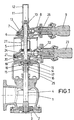
- a single drawing sheet is attached forming an integral part of said description, the single figure on said drawing sheet being by way of illustration and not restrictive in nature, showing, according to a side elevation and in diametric cross section, a valve for alumina producing plants implemented in accordance with the purpose of the present invention, said valve appearing in the shut position.
- valve which is being proposed is constituted of a valve body (1) in which is formed a valve seat (2) on which a gate (3) acts, said gate being conveniently in association with a shaft (4), axially displaceable by the action of a spindle (5) on which acts a nut (6), conveniently joined to a toothed crown wheel (7) which, via a bevel pinion (8), receives the movement of a reduction gear motor (9), all of this in such a way that the rotation of said reduction gear motor (9) in a determined direction produces the separation of the gate (3) with respect to the valve seat and its turning in the opposite direction produces similarly in the opposite direction the operation corresponding to shutting.
- the spindle (5) equipped at its free end and opposite to the valve itself with a diametric pin (10), the ends of which run in grooves (11) operationally formed in a hood (12) extension of the casing (13) which houses the crown wheel (7) and the transmission pinion (8), grooves (11) which permit the amplitude of axial movement necessary to achieve the also necessary amplitude of displacement in the gate (3), is finished at its lower extremity with a small enlargement (14) by means of which it is held axially with respect to an intermediate sleeve (15), which, in an axial direction, immobilises the spindle (5) with respect to the shaft (4), but which nonetheless permits the free rotational movement of said shaft (4) with respect to the spindle (5).
- the sleeve (15) acts also as driving element for the shaft (4) for which it is not only attached to the latter by screw thread (16), but also with the collaboration of a diametric pin (17).
- the sleeve (15) has a groove (18) in correspondence with one of its generators, in which sleeve runs a key (19) which, by permitting the free axial displacement of the sleeve ( 15), and consequently die free axial displacement of the assembly formed by the shaft (4) and the spindle (5), immobilises in an angular direction said sleeve (15) with respect to an external sleeve (20) to which is joined a toothed crown wheel (21), similar to the aforementioned crown wheel (7) which, through another bevel pinion (22), receives the movement of a second reduction gear motor (23), also similar to the reduction gear motor (9) already mentioned.
- This second transmission (21 - 22) is housed likewise in a casing (24) similar to the casing (13), the assembly of these elements being facilitated through the collaboration of brackets (25) and (26), fastened to each other and fastened to the valve body (1) itself, as can be seen in full detail in the figure.
- a dust guard cover (27) protects the transmission (21 - 22) mentioned, while permitting the necessary axial displacement of the sleeve (15).
- the reduction gear motor (23) When it is periodically necessary to carry out a valve self-cleaning operation, the reduction gear motor (23) is brought into operation, preferably also in an automatic way, said reduction gear motor (23) being clearly in a position supporting the gate (3) on the valve seat (2), said position determined in turn by the reduction gear motor (9), the reduction gear motor (23) driving the lower shaft (4) in its rotary movement exclusively, whilst the upper spindle (5) is held immobile, and producing the intended friction effect of the gate (3) against the valve seat (2), operation in which the reduction gear motor (9) can also participate, in such a manner that in parallel with the rotary movement of the gate (3) a slight forward movement thereof is produced, complementing the progressive rubbing away of the deposits or scale present in the contact zones between the gate (3) and valve seat (2).
Landscapes
- Engineering & Computer Science (AREA)
- General Engineering & Computer Science (AREA)
- Mechanical Engineering (AREA)
- Mechanically-Actuated Valves (AREA)
- Lift Valve (AREA)
- Electrically Driven Valve-Operating Means (AREA)
- Sliding Valves (AREA)
- Compounds Of Alkaline-Earth Elements, Aluminum Or Rare-Earth Metals (AREA)
- Catalysts (AREA)
- Valve Housings (AREA)
Claims (5)
- Soupape destinée à des installations de production d'alumine incorporant un corps de soupape dans lequel on établit un siège sur lequel agit un obturateur associé à un axe qui traverse le corps de soupape et qui par l'intermédiaire d'une transmission de type broche-écrou, reçoit un déplacement axial généré par tout élément moteur et déterminant des manoeuvres de rapprochement et de séparation du siège de soupape par rapport à l'obturateur, qui à son tour, est apte à, lors d'une situation de fermeture, recevoir un mouvement giratoire déterminant d'un frottement contre le siège de soupape, pour l'auto-nettoyage de l'ensemble, caractérisée en ce que l'obturateur (3) est solidaire d'un axe (4) mis en rapport, par son extrémité opposée audit obturateur (3), avec une broche (5), ledit axe (4) étant immobilisé axialement par rapport à la broche (5), mais apte à tourner librement par rapport à celle-ci, tout cela de manière que le déplacement de l'obturateur (3) pour l'ouverture et la fermeture de la soupape soit mis en oeuvre au moyen d'un déplacement axial fournit à l'ensemble broche-écrou (5 - 4) à travers la propre broche, tandis que le mouvement giratoire de l'obturateur (3), lors de la manoeuvre d'auto-nettoyage, c'est l'axe (4) qui le reçoit directement d'un élément moteur (23) étranger à l'élément moteur (9) qui agit sur la broche (5).
- Soupape destinée à des installations de production d'alumine, selon la revendication 1, caractérisée en ce que l'axe (4) et la broche (5) sont mis en rapport entre eux à travers une douille commune (15), qui reçoit en son sein une légère expansion (14) de l'extrémité correspondante de la broche (5), en permettant la rotation libre de celle-ci par rapport à ladite douille, ladite douille (15) se solidarisant, à la fois, de manière inamovible à l'axe (4), de préférence au moyen d'un filet (16) complémenté par une cheville diamétrale (17).
- Soupape destinée à des installations de production d'alumine, selon les revendications antérieures, caractérisée en ce que la douille (15) qui met en rapport l'axe (4) avec la broche (5) comprend une rainure (18) sur une de ses génératrices, dans laquelle joue une clavette (19), associée à une deuxième douille (20), enveloppante de l'antérieure et solidarisée à un plateau ou couronne (21) à travers lequel, avec la collaboration d'un pignon (22), l'axe (4) et par conséquent l'obturateur (3) reçoivent un mouvement giratoire de l'élément moteur (23), tout cela de manière que la clavette (19), en outre, de transmettre le mouvement giratoire à l'obturateur, permette le déplacement axial nécessaire de l'ensemble constitué par l'axe (4), la broche (5) et la douille (15) qui les met en rapport lors de la manoeuvre d'ouverture et de fermeture de la soupape.
- Soupape destinée à des installations de production d'alumine, selon les revendications antérieures, caractérisée en ce que le filet (6) pour le déplacement axial de la broche (5) reçoit solidairement un plateau ou couronne (7) qui, avec la collaboration d'un pignon conique (8), reçoit le mouvement du moteur (9), avec une transmission similaire à celle fournit par le mouvement giratoire à l'obturateur (3), la douille (5) demeurant immobilisée dans la direction angulaire avec la collaboration d'une cheville transversale (10), adéquatement solidarisée à l'extrémité libre de celle-ci, qui joue dans les rainures (11) d'un couvercle (12) dûment solidarisé à la carcasse (13) contenant les mécanismes de transmission correspondants.
- Soupape destinée à des installations de production d'alumine, selon les revendications antérieures, caractérisée en ce que lés éléments moteurs (9) et (23) sont susceptibles d'agir conjointement et automatiquement pendant la phase d'auto-nettoyage, de manière que, pendant que le moteur (23) fournit à l'obturateur (3) un mouvement giratoire continu, le moteur (9) fournit à son tour, au dit obturateur un mouvement lent d'avance vers le siège de soupape (2), au fur et à mesure qu'a lieu dans ces pièces, l'élimination des incrustations ou dépôts résiduaires de bauxite.
Applications Claiming Priority (2)
| Application Number | Priority Date | Filing Date | Title |
|---|---|---|---|
| PCT/ES1999/000196 WO2001001027A1 (fr) | 1999-06-29 | 1999-06-29 | Soupapes destinee a des installations de production d'alumine |
| US09/791,095 US6446660B1 (en) | 1999-06-29 | 2001-02-22 | Valve assembly with multiple mode actuators |
Publications (2)
| Publication Number | Publication Date |
|---|---|
| EP1116908A1 EP1116908A1 (fr) | 2001-07-18 |
| EP1116908B1 true EP1116908B1 (fr) | 2004-05-06 |
Family
ID=26155204
Family Applications (1)
| Application Number | Title | Priority Date | Filing Date |
|---|---|---|---|
| EP99932897A Expired - Lifetime EP1116908B1 (fr) | 1999-06-29 | 1999-06-29 | Soupapes destinee a des installations de production d'alumine |
Country Status (8)
| Country | Link |
|---|---|
| US (1) | US6446660B1 (fr) |
| EP (1) | EP1116908B1 (fr) |
| AT (1) | ATE266168T1 (fr) |
| AU (1) | AU766470B2 (fr) |
| DE (1) | DE69917052T2 (fr) |
| ES (1) | ES2221402T3 (fr) |
| PT (1) | PT1116908E (fr) |
| WO (1) | WO2001001027A1 (fr) |
Families Citing this family (33)
| Publication number | Priority date | Publication date | Assignee | Title |
|---|---|---|---|---|
| US7615893B2 (en) * | 2000-05-11 | 2009-11-10 | Cameron International Corporation | Electric control and supply system |
| DE20018563U1 (de) * | 2000-10-30 | 2002-03-21 | CAMERON GmbH, 29227 Celle | Betätigungsvorrichtung, insbesondere für eine Drosseleinrichtung |
| DE20115471U1 (de) | 2001-09-19 | 2003-02-20 | Biester, Klaus, 29342 Wienhausen | Universelles Energieversorgungssystem |
| DE20018562U1 (de) * | 2000-10-30 | 2002-03-21 | CAMERON GmbH, 29227 Celle | Absperrvorrichtung |
| DE20018548U1 (de) * | 2000-10-30 | 2002-03-21 | CAMERON GmbH, 29227 Celle | Drehverstellvorrichtung |
| AU2003230761A1 (en) * | 2002-03-29 | 2003-10-13 | Abbott Laboratories | Polymeric micelle formulations of hydrophobic compounds and methods |
| US6776393B2 (en) * | 2002-06-05 | 2004-08-17 | Glenn D. Burgos | Torque booster for valve operation |
| US6921546B2 (en) | 2003-02-20 | 2005-07-26 | Gemtron Corporation | Antimicrobial glass and glass-like products and method of preparing same |
| US6860464B1 (en) | 2004-01-29 | 2005-03-01 | Honeywell International Inc. | Electromechanical/pneumatic rocket engine valve actuator |
| DE102005041149A1 (de) * | 2005-07-19 | 2007-02-01 | Behr Gmbh & Co. Kg | Wärmeübertragerventileinrichtung |
| US20070145319A1 (en) * | 2005-12-28 | 2007-06-28 | Victor Hoernig | Flow control device |
| US20070259614A1 (en) * | 2006-05-08 | 2007-11-08 | Calsonickansei North America, Inc. | Actuation system for controlling movement of doors |
| FI118821B (fi) * | 2006-11-07 | 2008-03-31 | Juha Solantie | Laite venttiilien tai vastaavien avaamiseksi/sulkemiseksi |
| US8097128B1 (en) | 2007-06-01 | 2012-01-17 | Sherry Raymond C | Method and apparatus for purifying water |
| US8915453B1 (en) | 2007-06-01 | 2014-12-23 | Raymond C. Sherry | Expansion nozzle with continuous rotating stem |
| US8074671B2 (en) | 2007-06-06 | 2011-12-13 | Applied Magnetics Lab., Inc. | Self-cleaning valves for use in vacuum cleaners and other self-cleaning valves |
| JP5426769B2 (ja) * | 2009-07-14 | 2014-02-26 | ウッドウォード エイチアールティー インコーポレイティド | 冗長駆動モータを備える直接駆動型サーボバルブ |
| WO2011083432A2 (fr) * | 2010-01-07 | 2011-07-14 | Bray International, Inc. | Chapeau avec actionneur à engrenage pour vannes d'angle |
| WO2012046105A1 (fr) * | 2010-10-07 | 2012-04-12 | Bray International, Inc. | Vanne angulaire à 90° avec fermeture interne/externe accouplée à un réducteur blindé actionné par couronne et pignon à commande par moteur électrique/hydraulique avec support pour maintien d'élément de couple pneumatique |
| WO2012046106A1 (fr) * | 2010-10-08 | 2012-04-12 | Bray International, Inc. | Réducteur blindé actionné par couronne et pignon à commande par moteur électrique/hydraulique avec support pour maintien d'élément de couple pneumatique |
| DK2647892T3 (en) * | 2012-04-03 | 2015-02-09 | Phönix Armaturen Werke Bregel Gmbh | Shooting extensively a shooting house |
| US9151405B2 (en) | 2013-03-11 | 2015-10-06 | Kohler Co. | Transverse handle assembly for a valve |
| US9234606B2 (en) | 2013-03-11 | 2016-01-12 | Kohler Co. | Transverse handle assembly for a valve |
| JP6987771B2 (ja) | 2015-11-12 | 2022-01-05 | ライフ・アシスタント・リミテッドLife Assistant Ltd. | リーディングスレッドバルブ |
| CN107035874B (zh) * | 2017-05-31 | 2019-02-22 | 朱书红 | 一种密封阀 |
| US10465818B2 (en) * | 2017-07-26 | 2019-11-05 | Yuan Mei Corp. | Faucet connector |
| US10494797B2 (en) * | 2017-08-08 | 2019-12-03 | Armand Matossian | Shower control assembly |
| NO344270B1 (en) * | 2018-01-18 | 2019-10-21 | Fmc Kongsberg Subsea As | Subsea actuator with override function, as well as a method of operating an actuator |
| CN108644448B (zh) * | 2018-07-31 | 2024-06-14 | 宁波万诺宝通机电制造有限公司 | 一种燃气表电机阀 |
| FR3097610B1 (fr) * | 2019-06-20 | 2021-08-06 | Moving Magnet Tech | Vanne de réglage compacte |
| CN110906011B (zh) * | 2019-12-13 | 2024-06-14 | 鞍山电磁阀有限责任公司 | 电液一体式控制阀 |
| TW202407244A (zh) * | 2022-03-30 | 2024-02-16 | 日商小金井股份有限公司 | 流量控制閥 |
| GR20240100451A (el) * | 2024-06-19 | 2026-01-15 | Αυτοματισμοι Πεπιεσμενου Αερα - Εξοπλισμοι Συνεργειων Και Βουλκανιζατερ Ανων. Εμπ. Εταιρεια - Tecnopneumatic Α.Ε., | Συστημα καθαρισμου και ενισχυσης εμβολου ηλεκτρολυσης αλουμινας |
Family Cites Families (11)
| Publication number | Priority date | Publication date | Assignee | Title |
|---|---|---|---|---|
| US2177265A (en) * | 1933-07-17 | 1939-10-24 | Heyden Chem Fab | Method and apparatus for reducing the pressure of high pressure systems |
| US3311121A (en) * | 1963-06-18 | 1967-03-28 | E I M Company Inc | Automatic regrinding valve system |
| US3220431A (en) * | 1963-06-18 | 1965-11-30 | E I M Company Inc | Automatic regrinding valve apparatus |
| US3505888A (en) * | 1968-10-10 | 1970-04-14 | King Of Prussia Research & Dev | Rotary and linear dual motion valve operator |
| US3738183A (en) * | 1971-02-01 | 1973-06-12 | Philadelphia Gear Corp | Combination drive for valve operator |
| US4346728A (en) * | 1980-07-28 | 1982-08-31 | Anchor/Darling Industries, Inc. | Automated dual mode valve actuator |
| US4338961A (en) * | 1980-08-07 | 1982-07-13 | Anchor/Darling Valve Company | Valve for handling hot caustic alumina solution with provision for grinding |
| US4350322A (en) * | 1981-08-31 | 1982-09-21 | Grove Truseal Valve Company | High torque plug valve actuator |
| US4460009A (en) * | 1982-09-07 | 1984-07-17 | Ralph A. Hiller Company | Valve stem actuator |
| US4465091A (en) * | 1982-09-20 | 1984-08-14 | Kaiser Aluminum & Chemical Corporation | Improved self-grinding valve |
| US4760989A (en) * | 1987-02-02 | 1988-08-02 | Elliott Lynn T | Valve operator |
-
1999
- 1999-06-29 EP EP99932897A patent/EP1116908B1/fr not_active Expired - Lifetime
- 1999-06-29 AT AT99932897T patent/ATE266168T1/de not_active IP Right Cessation
- 1999-06-29 ES ES99932897T patent/ES2221402T3/es not_active Expired - Lifetime
- 1999-06-29 AU AU49118/99A patent/AU766470B2/en not_active Ceased
- 1999-06-29 WO PCT/ES1999/000196 patent/WO2001001027A1/fr not_active Ceased
- 1999-06-29 DE DE1999617052 patent/DE69917052T2/de not_active Expired - Lifetime
- 1999-06-29 PT PT99932897T patent/PT1116908E/pt unknown
-
2001
- 2001-02-22 US US09/791,095 patent/US6446660B1/en not_active Expired - Fee Related
Also Published As
| Publication number | Publication date |
|---|---|
| DE69917052T2 (de) | 2005-04-28 |
| US20020112760A1 (en) | 2002-08-22 |
| WO2001001027A1 (fr) | 2001-01-04 |
| WO2001001027A8 (fr) | 2001-03-15 |
| EP1116908A1 (fr) | 2001-07-18 |
| AU766470B2 (en) | 2003-10-16 |
| DE69917052D1 (de) | 2004-06-09 |
| AU4911899A (en) | 2001-01-31 |
| ATE266168T1 (de) | 2004-05-15 |
| US6446660B1 (en) | 2002-09-10 |
| PT1116908E (pt) | 2004-07-30 |
| ES2221402T3 (es) | 2004-12-16 |
Similar Documents
| Publication | Publication Date | Title |
|---|---|---|
| EP1116908B1 (fr) | Soupapes destinee a des installations de production d'alumine | |
| EP0349482B1 (fr) | Outil à main actionné par moteur | |
| US4775240A (en) | Closed parallel-rotor mixer with adjustable interaxial separation | |
| JP3277270B2 (ja) | 研磨機 | |
| GB2250003A (en) | Variable-effort automotive power steering. | |
| US2511741A (en) | Differential locking driving chuck | |
| EP0231720B1 (fr) | Dispositif pour fabriquer des cavités annulaires au fond de forures dans toutes sortes de surfaces | |
| WO2003070397A1 (fr) | Procede d'usinage d'un engrenage a denture interieure, et engrenage ainsi obtenu | |
| CN114382935A (zh) | 一种卫生级带排污的蝶形球阀 | |
| JP2001012678A (ja) | 不断水分岐配管の形成方法及びその装置 | |
| US5515886A (en) | Method and apparatus for repairing a junction pipe connection to a main pipe | |
| SE463478B (sv) | Drivanordning | |
| JPH0323287B2 (fr) | ||
| KR100603774B1 (ko) | 터릿 헤드 장치 | |
| GB2048420A (en) | Reciprocating drive | |
| SU1645057A1 (ru) | Поводковый патрон к круглошлифовальному станку | |
| SU772828A1 (ru) | Устройство дл шлифовани уплотнительных поверхностей задвижек | |
| SU1255042A3 (ru) | Суппорт токарного станка дл обработки глубоких кольцевых канавок | |
| US4209180A (en) | Self-centering work holding and positioning fixture for machine tools | |
| JPH0524436Y2 (fr) | ||
| US2261086A (en) | Crankshaft lathe | |
| US5711345A (en) | Method and apparatus for forming a control valve for hydraulic circuits | |
| US5732607A (en) | Portable machine tool | |
| KR100453643B1 (ko) | 궁형연삭기용 연삭축의 상하조정장치 | |
| JP2006043739A (ja) | 円筒状部材の内周面に溝群を形成する方法および装置 |
Legal Events
| Date | Code | Title | Description |
|---|---|---|---|
| PUAI | Public reference made under article 153(3) epc to a published international application that has entered the european phase |
Free format text: ORIGINAL CODE: 0009012 |
|
| 17P | Request for examination filed |
Effective date: 20010316 |
|
| AK | Designated contracting states |
Kind code of ref document: A1 Designated state(s): AT BE CH CY DE DK ES FI FR GB GR IE IT LI LU MC NL PT SE |
|
| GRAP | Despatch of communication of intention to grant a patent |
Free format text: ORIGINAL CODE: EPIDOSNIGR1 |
|
| GRAS | Grant fee paid |
Free format text: ORIGINAL CODE: EPIDOSNIGR3 |
|
| GRAA | (expected) grant |
Free format text: ORIGINAL CODE: 0009210 |
|
| AK | Designated contracting states |
Kind code of ref document: B1 Designated state(s): AT BE CH CY DE DK ES FI FR GB GR IE IT LI LU MC NL PT SE |
|
| PG25 | Lapsed in a contracting state [announced via postgrant information from national office to epo] |
Ref country code: NL Free format text: LAPSE BECAUSE OF FAILURE TO SUBMIT A TRANSLATION OF THE DESCRIPTION OR TO PAY THE FEE WITHIN THE PRESCRIBED TIME-LIMIT Effective date: 20040506 Ref country code: LI Free format text: LAPSE BECAUSE OF FAILURE TO SUBMIT A TRANSLATION OF THE DESCRIPTION OR TO PAY THE FEE WITHIN THE PRESCRIBED TIME-LIMIT Effective date: 20040506 Ref country code: FI Free format text: LAPSE BECAUSE OF FAILURE TO SUBMIT A TRANSLATION OF THE DESCRIPTION OR TO PAY THE FEE WITHIN THE PRESCRIBED TIME-LIMIT Effective date: 20040506 Ref country code: CY Free format text: LAPSE BECAUSE OF FAILURE TO SUBMIT A TRANSLATION OF THE DESCRIPTION OR TO PAY THE FEE WITHIN THE PRESCRIBED TIME-LIMIT Effective date: 20040506 Ref country code: CH Free format text: LAPSE BECAUSE OF FAILURE TO SUBMIT A TRANSLATION OF THE DESCRIPTION OR TO PAY THE FEE WITHIN THE PRESCRIBED TIME-LIMIT Effective date: 20040506 Ref country code: AT Free format text: LAPSE BECAUSE OF FAILURE TO SUBMIT A TRANSLATION OF THE DESCRIPTION OR TO PAY THE FEE WITHIN THE PRESCRIBED TIME-LIMIT Effective date: 20040506 |
|
| REG | Reference to a national code |
Ref country code: GB Ref legal event code: FG4D |
|
| REG | Reference to a national code |
Ref country code: CH Ref legal event code: EP |
|
| REF | Corresponds to: |
Ref document number: 69917052 Country of ref document: DE Date of ref document: 20040609 Kind code of ref document: P |
|
| REG | Reference to a national code |
Ref country code: IE Ref legal event code: FG4D |
|
| PG25 | Lapsed in a contracting state [announced via postgrant information from national office to epo] |
Ref country code: LU Free format text: LAPSE BECAUSE OF NON-PAYMENT OF DUE FEES Effective date: 20040629 |
|
| PG25 | Lapsed in a contracting state [announced via postgrant information from national office to epo] |
Ref country code: MC Free format text: LAPSE BECAUSE OF NON-PAYMENT OF DUE FEES Effective date: 20040630 |
|
| REG | Reference to a national code |
Ref country code: GR Ref legal event code: EP Ref document number: 20040401962 Country of ref document: GR |
|
| REG | Reference to a national code |
Ref country code: PT Ref legal event code: SC4A Free format text: AVAILABILITY OF NATIONAL TRANSLATION Effective date: 20040527 |
|
| PG25 | Lapsed in a contracting state [announced via postgrant information from national office to epo] |
Ref country code: SE Free format text: LAPSE BECAUSE OF FAILURE TO SUBMIT A TRANSLATION OF THE DESCRIPTION OR TO PAY THE FEE WITHIN THE PRESCRIBED TIME-LIMIT Effective date: 20040806 Ref country code: DK Free format text: LAPSE BECAUSE OF FAILURE TO SUBMIT A TRANSLATION OF THE DESCRIPTION OR TO PAY THE FEE WITHIN THE PRESCRIBED TIME-LIMIT Effective date: 20040806 |
|
| NLV1 | Nl: lapsed or annulled due to failure to fulfill the requirements of art. 29p and 29m of the patents act | ||
| REG | Reference to a national code |
Ref country code: CH Ref legal event code: PL |
|
| REG | Reference to a national code |
Ref country code: ES Ref legal event code: FG2A Ref document number: 2221402 Country of ref document: ES Kind code of ref document: T3 |
|
| ET | Fr: translation filed | ||
| PLBE | No opposition filed within time limit |
Free format text: ORIGINAL CODE: 0009261 |
|
| STAA | Information on the status of an ep patent application or granted ep patent |
Free format text: STATUS: NO OPPOSITION FILED WITHIN TIME LIMIT |
|
| 26N | No opposition filed |
Effective date: 20050208 |
|
| PGFP | Annual fee paid to national office [announced via postgrant information from national office to epo] |
Ref country code: PT Payment date: 20100628 Year of fee payment: 12 Ref country code: IE Payment date: 20100618 Year of fee payment: 12 Ref country code: ES Payment date: 20100408 Year of fee payment: 12 |
|
| PGFP | Annual fee paid to national office [announced via postgrant information from national office to epo] |
Ref country code: IT Payment date: 20100626 Year of fee payment: 12 |
|
| PGFP | Annual fee paid to national office [announced via postgrant information from national office to epo] |
Ref country code: BE Payment date: 20100611 Year of fee payment: 12 |
|
| PGFP | Annual fee paid to national office [announced via postgrant information from national office to epo] |
Ref country code: GB Payment date: 20100623 Year of fee payment: 12 Ref country code: FR Payment date: 20100715 Year of fee payment: 12 Ref country code: DE Payment date: 20100629 Year of fee payment: 12 |
|
| PGFP | Annual fee paid to national office [announced via postgrant information from national office to epo] |
Ref country code: GR Payment date: 20100621 Year of fee payment: 12 |
|
| BERE | Be: lapsed |
Owner name: *AMPO S. COOP. Effective date: 20110630 |
|
| REG | Reference to a national code |
Ref country code: PT Ref legal event code: MM4A Free format text: LAPSE DUE TO NON-PAYMENT OF FEES Effective date: 20111229 |
|
| PG25 | Lapsed in a contracting state [announced via postgrant information from national office to epo] |
Ref country code: PT Free format text: LAPSE BECAUSE OF NON-PAYMENT OF DUE FEES Effective date: 20111229 |
|
| GBPC | Gb: european patent ceased through non-payment of renewal fee |
Effective date: 20110629 |
|
| PG25 | Lapsed in a contracting state [announced via postgrant information from national office to epo] |
Ref country code: IT Free format text: LAPSE BECAUSE OF NON-PAYMENT OF DUE FEES Effective date: 20110629 |
|
| REG | Reference to a national code |
Ref country code: GR Ref legal event code: ML Ref document number: 20040401962 Country of ref document: GR Effective date: 20120105 |
|
| REG | Reference to a national code |
Ref country code: FR Ref legal event code: ST Effective date: 20120229 |
|
| REG | Reference to a national code |
Ref country code: IE Ref legal event code: MM4A |
|
| PG25 | Lapsed in a contracting state [announced via postgrant information from national office to epo] |
Ref country code: BE Free format text: LAPSE BECAUSE OF NON-PAYMENT OF DUE FEES Effective date: 20110630 |
|
| REG | Reference to a national code |
Ref country code: DE Ref legal event code: R119 Ref document number: 69917052 Country of ref document: DE Effective date: 20120103 |
|
| PG25 | Lapsed in a contracting state [announced via postgrant information from national office to epo] |
Ref country code: IE Free format text: LAPSE BECAUSE OF NON-PAYMENT OF DUE FEES Effective date: 20110629 Ref country code: DE Free format text: LAPSE BECAUSE OF NON-PAYMENT OF DUE FEES Effective date: 20120103 Ref country code: FR Free format text: LAPSE BECAUSE OF NON-PAYMENT OF DUE FEES Effective date: 20110630 |
|
| PG25 | Lapsed in a contracting state [announced via postgrant information from national office to epo] |
Ref country code: GR Free format text: LAPSE BECAUSE OF NON-PAYMENT OF DUE FEES Effective date: 20120105 |
|
| PG25 | Lapsed in a contracting state [announced via postgrant information from national office to epo] |
Ref country code: GB Free format text: LAPSE BECAUSE OF NON-PAYMENT OF DUE FEES Effective date: 20110629 |
|
| REG | Reference to a national code |
Ref country code: ES Ref legal event code: FD2A Effective date: 20130405 |
|
| PG25 | Lapsed in a contracting state [announced via postgrant information from national office to epo] |
Ref country code: ES Free format text: LAPSE BECAUSE OF NON-PAYMENT OF DUE FEES Effective date: 20110630 |