EP1116941A2 - Procédé et dispositif pour contrôler une balance dynamique - Google Patents
Procédé et dispositif pour contrôler une balance dynamique Download PDFInfo
- Publication number
- EP1116941A2 EP1116941A2 EP01250012A EP01250012A EP1116941A2 EP 1116941 A2 EP1116941 A2 EP 1116941A2 EP 01250012 A EP01250012 A EP 01250012A EP 01250012 A EP01250012 A EP 01250012A EP 1116941 A2 EP1116941 A2 EP 1116941A2
- Authority
- EP
- European Patent Office
- Prior art keywords
- transport
- weighing
- speed
- transport device
- goods
- Prior art date
- Legal status (The legal status is an assumption and is not a legal conclusion. Google has not performed a legal analysis and makes no representation as to the accuracy of the status listed.)
- Granted
Links
- 238000005303 weighing Methods 0.000 title claims abstract description 134
- 238000000034 method Methods 0.000 title claims abstract description 27
- 238000005259 measurement Methods 0.000 claims abstract description 59
- 238000012545 processing Methods 0.000 claims abstract description 34
- 238000011144 upstream manufacturing Methods 0.000 claims abstract description 32
- 238000011156 evaluation Methods 0.000 claims description 21
- 230000015654 memory Effects 0.000 claims description 10
- 230000008569 process Effects 0.000 claims description 10
- 230000008859 change Effects 0.000 claims description 6
- 230000002441 reversible effect Effects 0.000 claims description 4
- 230000006870 function Effects 0.000 claims description 2
- 238000011143 downstream manufacturing Methods 0.000 claims 8
- 230000001419 dependent effect Effects 0.000 abstract 1
- 230000002829 reductive effect Effects 0.000 description 17
- 238000010586 diagram Methods 0.000 description 9
- 230000003068 static effect Effects 0.000 description 9
- 241000408529 Libra Species 0.000 description 3
- 230000005540 biological transmission Effects 0.000 description 3
- 238000001514 detection method Methods 0.000 description 3
- 238000012805 post-processing Methods 0.000 description 3
- 230000006399 behavior Effects 0.000 description 2
- 238000004891 communication Methods 0.000 description 2
- 230000000694 effects Effects 0.000 description 2
- 230000007723 transport mechanism Effects 0.000 description 2
- VVQNEPGJFQJSBK-UHFFFAOYSA-N Methyl methacrylate Chemical compound COC(=O)C(C)=C VVQNEPGJFQJSBK-UHFFFAOYSA-N 0.000 description 1
- 229920005372 Plexiglas® Polymers 0.000 description 1
- 230000004913 activation Effects 0.000 description 1
- 230000006978 adaptation Effects 0.000 description 1
- 230000000712 assembly Effects 0.000 description 1
- 238000000429 assembly Methods 0.000 description 1
- 230000004888 barrier function Effects 0.000 description 1
- 238000005452 bending Methods 0.000 description 1
- 230000008878 coupling Effects 0.000 description 1
- 238000010168 coupling process Methods 0.000 description 1
- 238000005859 coupling reaction Methods 0.000 description 1
- 238000013016 damping Methods 0.000 description 1
- 238000013461 design Methods 0.000 description 1
- 238000011161 development Methods 0.000 description 1
- 230000018109 developmental process Effects 0.000 description 1
- 230000005484 gravity Effects 0.000 description 1
- 230000004446 light reflex Effects 0.000 description 1
- 238000005457 optimization Methods 0.000 description 1
- 230000036961 partial effect Effects 0.000 description 1
- 230000000717 retained effect Effects 0.000 description 1
- 238000009420 retrofitting Methods 0.000 description 1
- 239000000725 suspension Substances 0.000 description 1
- 238000012360 testing method Methods 0.000 description 1
- 238000013519 translation Methods 0.000 description 1
- 230000001960 triggered effect Effects 0.000 description 1
- 230000003936 working memory Effects 0.000 description 1
Images


Classifications
-
- G—PHYSICS
- G01—MEASURING; TESTING
- G01G—WEIGHING
- G01G19/00—Weighing apparatus or methods adapted for special purposes not provided for in the preceding groups
- G01G19/002—Weighing apparatus or methods adapted for special purposes not provided for in the preceding groups for postal parcels and letters
- G01G19/005—Weighing apparatus or methods adapted for special purposes not provided for in the preceding groups for postal parcels and letters with electric or electronic computing means
-
- G—PHYSICS
- G01—MEASURING; TESTING
- G01G—WEIGHING
- G01G19/00—Weighing apparatus or methods adapted for special purposes not provided for in the preceding groups
- G01G19/40—Weighing apparatus or methods adapted for special purposes not provided for in the preceding groups with provisions for indicating, recording, or computing price or other quantities dependent on the weight
- G01G19/413—Weighing apparatus or methods adapted for special purposes not provided for in the preceding groups with provisions for indicating, recording, or computing price or other quantities dependent on the weight using electromechanical or electronic computing means
- G01G19/414—Weighing apparatus or methods adapted for special purposes not provided for in the preceding groups with provisions for indicating, recording, or computing price or other quantities dependent on the weight using electromechanical or electronic computing means using electronic computing means only
- G01G19/4148—Weighing apparatus or methods adapted for special purposes not provided for in the preceding groups with provisions for indicating, recording, or computing price or other quantities dependent on the weight using electromechanical or electronic computing means using electronic computing means only for controlling postal rate in articles to be mailed
-
- G—PHYSICS
- G07—CHECKING-DEVICES
- G07B—TICKET-ISSUING APPARATUS; FARE-REGISTERING APPARATUS; FRANKING APPARATUS
- G07B17/00—Franking apparatus
- G07B17/00459—Details relating to mailpieces in a franking system
- G07B17/00661—Sensing or measuring mailpieces
-
- G—PHYSICS
- G07—CHECKING-DEVICES
- G07B—TICKET-ISSUING APPARATUS; FARE-REGISTERING APPARATUS; FRANKING APPARATUS
- G07B17/00—Franking apparatus
- G07B17/00459—Details relating to mailpieces in a franking system
- G07B17/00467—Transporting mailpieces
-
- G—PHYSICS
- G07—CHECKING-DEVICES
- G07B—TICKET-ISSUING APPARATUS; FARE-REGISTERING APPARATUS; FRANKING APPARATUS
- G07B17/00—Franking apparatus
- G07B17/00459—Details relating to mailpieces in a franking system
- G07B17/00661—Sensing or measuring mailpieces
- G07B2017/00701—Measuring the weight of mailpieces
Definitions
- the invention relates to a method for controlling a dynamic Balance system, hereinafter referred to as dynamic balance, according to the Preamble of claim 1 and a corresponding arrangement therefor of the preamble of claim 8. Weigh such dynamic scales Weighed well during the transport process and are specially in Post processing systems used.
- the solution aims in particular at one effective mixed mail processing in a dynamic scale and Franking device.
- Mixed mail is understood to mean an unsorted stack of mail pieces, which are aligned with the side to be printed on. When letters are subsequently spoken of, this also occurs for all the other possible items of mail that differ in format, thickness and weight.
- the method and arrangement are suitable for users of mail processing systems both with a dynamic scale and postage-calculating franking machine and with dynamic postage computer scales and franking devices.
- a dynamic weighing station is arranged behind a singling station. The letters created as a stack are first automatically separated and then taken over by the dynamic weighing station and their weight is determined. The weight is determined with an accuracy that enables the letters to be assigned to the correct postage class.
- the postage is automatically transferred to the connected franking unit, offset and printed on the letter.
- the weight sensor When the letter hits the weighing plate and its transport, mechanical vibrations are transmitted to the weight sensor, the amplitude of which depends on the letter weight, the direction and speed of transport, the distribution of the letter mass and its rigidity. These disturbing vibrations limit the accuracy of the measurement result.
- ⁇ 1g stated up to a letter weight of 1000g.
- the swinging of the dynamic scales takes more time when transporting heavy items of mail with a weight of more than 1000g due to the vibration influences on the weighing system. All even heavier letters will usually be weighed separately using a suitable static balance.
- the appropriate weight or postage can be entered manually into the franking unit.
- the automatic process is interrupted.
- a particular disadvantage is the fact that the mail shipper cannot predict whether the special letter which he is stacking together with the others will exceed these weight limits or not.
- the upstream user station can be a scale and the downstream user station is a postage meter.
- a continuous moving letter can be completely picked up by the scales. With mixed mail the likelihood is greater that the balance will give an incorrect measurement result determined.
- the measuring time depends on the dimensions of the letter elevated.
- the weighing range is enlarged and a control compartment is arranged. The would increase the length of the entire mail processing system, however is not possible without major retrofitting.
- the dynamic scale has provided a weighing plate for the letters that is designed to be resistant to bending and torsion, which is coupled to a weighing cell at the approximate location of the common center of gravity of the weighing plate and a letter arranged in the center of the weighing plate with the maximum permissible weight and the largest permissible dimensions.
- the aforementioned coupling of the weighing plate to the weighing cell minimizes the negative effects of the load arm.
- a method of controlling a dynamic scale the mixed mail can process with different size and thickness, and in at least two operating modes can be operated is the German patent application DE 19860296.0 removable.
- dynamic operating mode before Beginning of a first measurement period for a postal item regardless of its Format with a preset value Transport speed fed when the letter is in the infeed of the dynamic scale.
- Transport speed fed when the letter is in the infeed of the dynamic scale.
- An activation of the speed control for the engine occurs again when the letter is in the phase of dynamic Scale is located. The letter then passes through the franking machine or further processing stations of the mail processing system.
- the scale is from dynamic to semi-dynamic Switchable operating mode. If the balance is an invalid measurement result has determined, a backward movement of the incorrectly measured letter triggered within the scale. With the now following semi-dynamic Weighing, the scale stops the conveyor belt until the scale turns on has determined the correct measurement result.
- the highest possible proportion of mail from the mail sender should be dynamic Mode, with manual intervention during the Postprocessing is usually not necessary.
- the object is with the features of the method according to claim 1 and with solved the features of an arrangement according to claim 8.
- the measuring arrangement of the dynamic scale is coupled to a conveyor for the continuous transport of letters.
- the conveying device hereinafter referred to as the conveying device, in which the conveying direction is reversible and thus letter transport can be carried out both upstream in the direction of the system inlet and downstream to the further processing device.
- the piece of mail hereinafter referred to as a letter, is transported downstream to the further processing station at a first speed, a weight measurement being carried out with an evaluation of the plausibility of the measurement result.
- non-plausibility i.e.
- the measurement result of the letter weight is not plausible or is declared invalid, a dynamic re-measurement of the weight is carried out, the letter being transported back into a predetermined position up to the letter inlet by reversing the transport direction of the transport device up to the letter inlet .
- its weight is determined in a dynamic weighing step without stopping. If the final measurement is successful and the weighing result is plausible, the letter is transported downstream without further weighing to the further processing station. The removal can take place at a maximum speed that can be predetermined for the dynamic scale, which is greater than the first and second speeds.
- the measurement time is insufficient or the measurement result of the re-measurement is not plausible, a further re-measurement can be carried out.
- the letter Upon reaching the predetermined position in the letter infeed, the letter is transported a second time downstream at a third speed by reversing the transport device, the dynamic scale determining the weight of the letter by means of a further measurement during transport. If the result of the re-measurement is plausible or valid, the letter is transported to the next processing station at the speed required for the system run without Interference is preset.
- Another possibility of the invention is that when a Weighing value that is not plausible, that the weighing system is in a dynamic state to leave, but when transporting the letter back by reversing the Transport direction of the transport device no weight determination to carry out the natural vibrations of the weighing system dampen. Only when the letter reaches the predetermined position in the infeed area has reached and the transport of the letter downstream through the Transport equipment was resumed, a repeat of the Weight determination of the letter carried out during transport.
- the invention is not in itself known weighing methods limited. It can be a weighing cell with old or new weighing methods are also used.
- the scales coupled further processing device receives weighed letters from a transport device for the dynamic scale.
- a control unit is included a load cell, sensors and the transport device. Latter is designed for two-way transport.
- Sensors for the feedback of the letter position arranged in the transport route are the transport device in the dynamic scale a controllable Includes drive and the control unit has a microprocessor that with a program memory and a non-volatile memory are connected, the microprocessor being programmed such that the letter is upstream towards the first processing station at a second speed or downstream with a first speed is transported.
- the microprocessor switches in Depends on the result of the weight determination from the first to one second operating mode. The measurement result is valid in the first Operating mode of the letter delivered to another processing device.
- the system automatically switches to a second Operating mode switched.
- the second operating mode the letter upstream towards the first processing station with a second Speed transported and weighed or accordingly at very high poor vibration behavior of the weighing system without weighing directly to the predetermined position transported back in the inlet area. Only after Resumption of the direction of transport of the letter with a third Speed downstream, this is dynamically weighed.
- the Microprocessor determines the level of the second and third speed depending on the extent to which the measuring arrangement with the Weighing cell has already settled on the weight.
- the second and third speed in terms of amount is different or the same as the first, but less than a maximum The speed at which a letter is downstream towards the other Processing station is transported without weight determination.
- FIG. 1 shows a perspective view of a dynamic scale 10 shown, which for the transport of letters standing on the edge A is trained.
- the latter rest on a weighing plate 6, which is in a rear Guide wall 1 of the scale is arranged in a recess 11.
- Sensors S1 and S2 arranged.
- fork lights or Light reflex light barriers suitable, which the rear or front edge of a Detect letter A when it is transported to the weighing plate 6.
- the Sensor S1 is upstream near the start of the letter A path the weighing plate (seen in the direction of transport).
- a transport device 4 In the amount of one Lower guide wall 3 of the scale is a transport device 4 with a - invisible - conveyor belt 41.
- the rear guide wall 1 is light, preferably 18 ° to the vertical, inclined to the rear. That corresponds to one Optimization angle already determined for automatic letter feeding and a franking machine (DE 196 05 014 C1 and DE 196 05 015 C1).
- the lower one Guide wall 3 is orthogonal to the rear and consequently also to the front Cover plate 2 arranged. This creates a defined letter position and a harmonious adaptation to the upstream and downstream devices achieved.
- the Front cover plate 2 is made of plexiglass, for example. All of the above Assemblies or parts are on a corresponding intermediate pieces Chassis 5 attached. Further details on the structural design of the scale can be found in German patent application DE 198 33 767.1.
- the control unit 20 of a dynamic scale 10 has a microprocessor 21 which is connected to a program memory 22, to a non-volatile memory 23 and to interfaces for input and output 24, 25. An associated set of parameters for the evaluation of the measured values is stored in the non-volatile memory 23 in association with predetermined speeds.
- the microprocessor 21 has an internal and possibly an additional external working memory. Alternatively, a microcontroller with integrated memories can be used.
- the microprocessor 21 is operationally connected on the output side to a motor 49 of the transport device 4 of the dynamic scale 1 via a driver 26 and on the input side to an encoder 50, sensors S1, S2 and a weighing cell 7 in order to receive sensor signals, encoder signals and weight data and around Send control commands to the transport device 4.
- the motor 49 in the transport device 4 of the scale 10 is a motor 49 that can be switched in the direction of rotation and has a controllable rotational speed for setting the transport speed and for changing the transport direction.
- the transport device 4 preferably contains a direct current motor, which is fed with direct current pulses, a certain speed being set on the basis of the ratio of the pulse length to the pulse pause.
- the motor 49 drives a drive roller 485.
- the latter can act directly on the letter or indirectly, preferably via a conveyor belt 41, which can be tensioned with a tensioning device 48.
- the transport device 4 executes a forward movement of the relevant letter A within the scale downstream at a specific first speed which does not exceed the transport speed in the further processing station.
- Corresponding control commands can be generated by the control unit 20, by means of which a second speed is generated in a second operating mode, in order to possibly slow down the transport speed in the scale so that sufficient measuring time is available for a dynamic measurement.
- the transport device 4 executes a backward movement of the relevant letter within the scale 10 upstream at the specific second speed.
- the motor 49 which is supplied with direct current pulses, supplies a certain speed due to the ratio of the pulse length to the pulse pause, as a result of which a certain speed is set on the conveyor belt 41.
- Letter A is dynamically weighed a second time upstream to a predetermined position in the inlet area during the return transport.
- the microprocessor 21 switches the speed of the backward movement of the letter A depending on the result of the first non-plausible weight determination.
- the height of the transport speed depends on the extent to which the measuring arrangement with the weighing cell 7 has already settled to the weight during the first measurement.
- the drive is controlled by the microprocessor 21 in that the transport speed for the removal is set greater than the first speed or a third speed is set for a repetition of the weight determination.
- the transport speed for the repeat measurement can be slowed down.
- vibrations caused by heavy letters and stochastic influences such as vibrations at the location of the dynamic scale 10 can be reduced.
- the letter A is conveyed to a further processing device, preferably a franking machine, at a transport speed adapted to the mail processing.
- the motor 49 supplies a certain speed based on the ratio of the pulse length to the pulse pause, as a result of which a certain speed is set on the transport device.
- the transport device 4 of the scale 10 a switchable drive and that the Controller 20 includes driver 26, which is between the drive and the controller is switched, with which the transport direction of the balance can be reversed, to the letter to the beginning of the weighing plate 6 in the second operating mode to be transported back and to be reweighed during the return transport to execute.
- the driver 26 can also be designed as a relay.
- the of the Control unit 20 outgoing control signals control the relay, which the Voltage for the drive motors of the transport device switches.
- the motor 49 is possibly connected to the drive roller 485 via a suitable gear 44.
- the transmission 44 can be both a gear transmission and a belt transmission his.
- the transport device 4 comprises the scale a motor with switchable gearbox that in a different translation and Direction of rotation can be switched.
- the weight is determined in the first operating mode, during the Measuring time range in which the letter A downstream in the direction of the other Processing station is transported at a first speed. in the Measuring time range, measured values are sorted according to size and on middle measured value determined. As a result of the weight determination a determined measured value is declared valid if predetermined limit values and Switch-off criteria were not exceeded. More details on Weight determination in the balance can be found in DE 198 60 294.4 A.
- Exceeding the switch-off criteria is a measure of the extent to which the first Operating mode the measuring arrangement with the load cell already on the weight has been settled. If in the first operating mode Measuring arrangement with the load cell not sufficient for the weight has settled, then in the second operating mode the letter A transported back upstream at a second speed, the smaller than the first speed is. If in the first operating mode Measuring arrangement with the weighing cell has already settled to the weight, but the test result is not plausible, then in the second operating mode the letter is transported back upstream at a second speed, which can be greater than or equal to the first speed.
- the letter A is in a predetermined position stopped in the infeed area and with a on the dynamic scale (10) coordinated maximum speed transported to the franking machine. If the weight value is not plausible, the letter A will be sent at a speed equal to or less than the first speed during transportation weighed again downstream of the franking machine.
- FIG. 3 shows a speed / time diagram for the control of the dynamic scale in the event that a re-weighing is required after weighing.
- the scale is in the first operating mode when a letter A with a (positive) transport speed V 1 is fed in at time t 0 .
- the measurement (checkerboard pattern) begins at time t 1 and ends at time t 2 .
- input impacts on the weighing plate 6 when the letter is fed in are generally already reduced. Weighing is required if the input impacts on the weighing plate 6 have not yet been reduced or have not been reduced enough when the letter is fed. Such a requirement is recognized when evaluating the measured values. Massive letters shoot at least partially beyond the rear end of the scale at the letter outlet.
- the dotted line shown in FIG. 3 shows static reweighing beginning at time t 3 and ending at time t 7 .
- Letter A can only be handed over to the downstream franking machine at time t a .
- a static weighing in the second operating mode can also be found in DE 198 60 294.4 and will not be described further here.
- dynamic weighing can now take place in a second operating mode if the letter A is transported upstream to the entry area and weighed at a second (negative) speed.
- Dynamic reweighing is shown as a line pattern area and begins at time t3 and ends at time t 6 , the amount of the second speed V 2b being lower than the first speed V 1 of the first operating mode.
- the letter is handed over at time t b .
- Dynamic weighing is shown as a black area and begins at time t 4 and ends at time t 5 , the amount of the second speed V 2c being greater than the first speed V 1 of the first operating mode.
- the letter is handed over to a franking machine at the time t c , with the following being true: time t c ⁇ t b ⁇ t a .
- dynamic dynamic weighing is carried out again after the letter A at a second (negative speed) initially is transported back to the inlet area up to a predetermined position, from which there is a sufficient distance downstream towards the next processing facility extends to reliable in dynamic Operation of the dynamic scale 10 a weight determination of the letter A to be repeated again if none due to the measurement during forward transport plausible weight value could be determined.
- the sensor S1 in the infeed area indicates after recognizing the letter position the letter edge of the letter A, a corresponding signal to the control unit 20 , which causes the motor 49 to reverse direction is driven and the letter A at maximum speed downstream transported to the next processing facility if a plausible Weight value was determined or at a speed less than or equal to the first speed, if after the first weight determination no plausible weight value is present.
- controller 20 depends on it to what extent the measuring arrangement with the weighing cell already depends on the weight of the Letter A has settled, the re-measurement with higher Transport speed of the letter takes place.
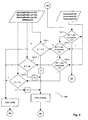
- FIG. 4a shows the flow diagram for the control of the dynamic scale.
- the microprocessor can determine the front edge of the letter by means of the sensor S1 at the letter inlet and starts the process (in step 99).
- Weighing values are constantly supplied by the weighing cell 7 for the purpose of weight determination.
- the microprocessor has detected the trailing edge of the letter by means of the sensor S1 at the letter inlet (in step 101) and starts (point B1) the sorting subroutine (in step 102) of the weighing measured values M1, M2, M3, ..., M7, ... , Mx, ... M14, which can be found in German patent application DE 198 60 294.4.
- a branch is made to a sub-step 103a of evaluation step 103. If the direction of movement is set forward (downstream), a branch is made to a sub-step 103b.
- the microprocessor uses the sensor S2 at the letter outlet 32 to recognize the front edge of the letter (in step 103b) and branches to a step 104.
- the one that has elapsed from the reference point B1 for a detection of the predetermined number of last measured values Time range is referred to as measurement time range T1.
- the microprocessor now forms a decision parameter E in step 104 as the difference value between the sorted largest and smallest value. If the letter leading edge at the outlet has not yet been detected in sub-step 103b, a branch is made back to a reference point B1 at the input of sorting step 102. If the movement is set to zero or backwards (upstream), a branch is made from sub-step 103a to a sub-step 103c of evaluation step 103. If the movement is reduced to zero, a branch is made from sub-step 103c to sub-step 103d of evaluation step 103 and semi-dynamic weighing is carried out. Otherwise, dynamic weighing is carried out while reversing and branching to sub-step 103 e of evaluation step 103.
- a branch is made to a reference point B1 at the input of sorting step 102. Otherwise, ie after the acquisition of the measured values M1 to Mx or M1 to Mi ⁇ M14, the number of which is again specified by the parameter P3, a reference point B2 is reached. Decision parameter E can now be formed again in step 104 as the difference value between the sorted largest and smallest value. A reference point B3 is then reached and the microprocessor now starts the query for at least one overload in step 105.
- the measured value M7 lies, for example, midway between the largest and the smallest value and is compared with the highest overload limit value G3.
- the lap counter is queried for a timeout after Z> 4. If a criterion is met, ie overload or Z> 4, point B8 is reached. Any overload error or timeout that may be present is further evaluated (in step 111) and the balance is stopped. If there is no overload or timeout, then a further query step 106 determines whether the value is valid or invalid. For this purpose, a subroutine is called, which is explained in more detail with reference to FIG. 5.
- the difference value E from the first M1 and fourteenth sorted measured value M14 should lie within the weight range of one of the switch-off criteria A1, A2 or A3.
- step 107 can now be used to determine the weighing value, in which a subroutine is called and processed (reference point B5).
- step 107 If the weight is successfully determined in step 107, the letter is ejected in a sub-step 116 and the weighing result is transferred to the franking machine.
- the motor 49 or the gear 44 is set to the direction of movement forward (downstream).
- the subroutine can also be found in the aforementioned patent application DE 198 60 294.4. If the scale is not stopped (for example manually), which is queried in step 112, then branching back from step 112 to step 100. If a stop command is found, the end of the operation of the scale is reached (step 113).
- step 106 determines whether the switch-off criteria have been exceeded in step 106 has shown that at least one switch-off criterion has been met, and a limit value may also have been exceeded.
- step 108 the motor control 20, 26, 44, 49 is switched over, here to initiate the return transport of the letter into a weighing position and then to carry out a reweighing when reversing.
- the microprocessor selects and enters a setpoint n1, n2, n3 for speed control before switching to the second operating mode (reference point B7).
- the current speed n is determined by the encoder 50 and used for speed control in step 108.
- the speed control (not shown) is switched off in the actual measuring interval for the weighing mode.
- steps 109 and 110 then branch back to the reference point B1 to the sorting step 102 and then via the query steps 103a, 103c, 103e to step 104 for forming the difference in the weighing mode.
- the measurement evaluation begins with the branching to the reference point B1. Before that, the microprocessor can use sensor S2 (in optional step 117, not shown) to recognize that the front edge of the letter no longer covers the outlet 32 of the scale.
- the measured values Mx delivered by the weighing cell 7 are sorted and stored in step 102.
- the measuring interval is determined retrospectively for x measured values, which are still saved when the inlet is reached.
- sensor S1 therefore evaluates whether the trailing edge of the letter has reached the inlet.
- the inlet (not visible in FIG. 1) is shaped like the outlet 32 on the scale. If the letter trailing edge has not yet reached the infeed, then branching back from step 103e to the reference point B1 at the beginning of step 102. If the trailing edge of the letter has reached the inlet, then the reference point B2 is reached at the beginning of step 104 for forming the difference in the weighing mode.
- the reference point B4 is reached if the overload value or the lap criterion (time out) or the switch-off criteria are not exceeded. Otherwise, if the switch-off criteria are exceeded, the reference point B7 has been reached.
- FIG. 4b shows the flow diagram for the control of the dynamic Libra.
- the microprocessor has the sensor S1 at the letter inlet Letter trailing edge recognized (in step 101) and starts (point B1) that Sort subroutine (in step 102) of the weighing measured values M1, M2, M3, ..., M7, ..., Mx, ... M14, which the German patent application DE198 60 294.4 can be seen.
- From Step 102 branches to a sub-step 103a of the evaluation step 103.
- the microprocessor recognizes by means of the sensor S2 at the letter outlet 32 the letter leading edge (in step 103b) and branches out a step 104.
- the from the reference point B1 for a detection of the predetermined number of last measured values elapsed time range is as Measuring time range called T1.
- the microprocessor forms one after the latter Decision parameter E in step 104 as the difference value between the sorted largest and smallest value. If the front edge of the letter at the outlet in the Sub-step 103b has not yet been detected, then a reference point is used B1 branches back at the input of sorting step 102.
- a branch is made from sub-step 103a to a sub-step 103c of evaluation step 103. If the movement is reduced to zero, a branch is made from sub-step 103c to sub-step 103d of evaluation step 103 and semi-dynamic weighing is carried out.
- a reference point B2 is reached and the decision parameter E is formed in step 104 as the difference value between the sorted largest and smallest value.
- a reference point B3 is then reached and the microprocessor now starts the query for at least one overload in step 105.
- the measured value M7 lies, for example, midway between the largest and the smallest value and is compared with the highest overload limit value G3.
- the lap counter is queried after Z> 4 for exceeding (time out). If a criterion is met, ie overload or Z> 4, point B8 is reached. A possible overload error or time out is further evaluated (in step 111) and the scale is stopped. If there is no overload or timeout, then a further query step 106 determines whether the value is valid or invalid. For this purpose, a sub-program is called, which is explained in more detail in the aforementioned, not previously published German patent application P 198 60 294.4.
- the difference value E from the first M1 and fourteenth sorted measured value M14 should lie within the weight range of one of the switch-off criteria A1, A2 or A3. It lies, for example, within a range defined by the second switch-off criterion A2 and thus results in valid measured values.
- Switch-off criterion A1 applies to light mail pieces
- switch-off criterion A2 applies to medium-weight mail pieces
- switch-off criterion A3 applies to heavy mail pieces. If the check of the exceeding of the limit values and switch-off criteria has shown the validity of the measured value M7 in the middle, none of the switch-off criteria is fulfilled (reference point B4).
- step 107 determines the weighing value, in which a subroutine is called and processed (reference point B5). If the weight is successfully determined in step 107, the letter is ejected in a sub-step 116 and the weighing result is transferred to the franking machine. In addition, the motor 49 or the gear 44 is set to the direction of movement forward (downstream).
- the subroutine can also be found in the aforementioned German patent application P 198 60 294.4, which has not been previously published. If the scale is not stopped (for example manually), which is queried in step 112, then branching back from step 112 to step 100.
- step 113 If a stop command is found, the end of the operation of the scale is reached (step 113). Otherwise, in the case of invalid measured values, that is to say if the check that the switch-off criteria have been exceeded in step 106 has shown that at least one switch-off criterion has been met, and a limit value may also have been exceeded, reference point B7 is reached and branched to step 109, where the motor control 20, 26, 44, 49 is switched over, here to initiate the return transport of the mail item into a weighing position and then later to carry out a re-weighing when driving forward.
- the microprocessor selects and enters a setpoint n2 for speed control during return transport at a second speed V2 before switching to the second operating mode (reference point B7).
- the current speed n is determined by the encoder 50 and used for speed control in step 109. From step 109, branches 108 and 110 then branch back to reference point B1 to sorting step 102 and then branches via query steps 103a, 103c, 103e to step 109 for switching the letter transport direction for the weighing mode. To ensure that a sufficient measuring path is available for reweighing, a backward movement determined by sub-steps 103a and 103c is carried out beforehand. There is a waiting loop, ie there is now a branch to sub-step 103e of evaluation step 103 as long as the rear of the letter at the inlet 31 of the balance has not yet been detected by sensor S1 and microprocessor in sub-step 103e. If the rear edge of the letter reaches the inlet 31 of the scale, a branch is made to a step 109 in order to reverse the direction of movement to "forward" again.
- the speed control (not shown) is switched off again for the weighing mode in the actual measuring interval.
- the measurement evaluation begins again with the branching to the reference point B1.
- forward driving determined by sub-steps 103a is carried out.
- the microprocessor now controls the motor 49 with the same parameters (n1) as in the first run.
- the dynamic weighing is repeated during the letter transport downstream.
- steps 102, 103 and 104 are carried out.
- the system branches back to reference point B1 at the input of sorting step 102. Otherwise the reference point B2 is reached when the microprocessor detects by means of the sensor S2 that the front edge of the letter reaches or covers the outlet 32 of the scale.
- the measured values Mx delivered by the weighing cell 7 are sorted and stored in step 102.
- the measurement interval is determined retrospectively for x measurement values, which are still stored when the outlet 32 is reached.
- the reference point B3 is reached after execution of the step 104 for forming the difference in the weighing mode.
- the reference point B4 is reached if the overload value or the round criterion (time out) or the switch-off criteria are not exceeded. Otherwise, if the switch-off criteria are exceeded, the reference point B7 has been reached.
- the motor controller switches to the direction of movement backward (upstream) in step 109.
- the letter is only transported a short distance backwards because in step 108 the exceeding of the criterion Z> 2 is recognized and a branch is made to a step 115 engine stop. However, even during the stopping process, the letter is moved back a little so that it completely comes to rest on the weighing pan 5. If the movement is reduced to zero, semi-dynamic weighing is carried out.
- steps 102, 103a, 103c and 103d are carried out and a difference is formed in step 104 if all measured values M1 to Mi are stored with i> 14, the number of which is predetermined by parameter P3. Large and heavy mail items in particular have long settling times.
- the number of measured values M1 to Mx during the static final measurement is therefore greater than fourteen.
- the measurement ends after stop 112 with a plausible result or at stop 116 with an implausible result.
- Figure 5 shows the partial flowchart overload and switch-off criterion.
- the seventh measured value is compared with a limit value G3, G1 and G2. In this way, the weight class to which the measured values can be assigned can be determined. If the seventh measured value M7 is greater than the third limit value G3, then an overload is determined and the reference point B8 is reached. Otherwise M7 ⁇ G3 and it is now checked whether the seventh measured value is greater than the first limit value G1. If this is the case, ie G1 ⁇ M7 ⁇ G3 is present, then it is checked whether the seventh measured value is greater than the second limit value G2.
- a branch is made to query step 106-3.
- E must not be greater than the third query criterion A3 if the measured values acquired are to be valid. Otherwise, branching from query step 105-2 or 105-3 to query step 106-1 or 106-2.
- the difference E is compared with a value A1, A2 and A3 as a switch-off criterion. If the difference E is greater than the switch-off criterion A1, A2 or A3, then the measured values are invalid (reference point B7).
- the measured values are valid (reference point B4) if the difference E lies within the switch-off criterion A1, A2 or A3.
- the terms "limit values” and "switch-off criteria" are explained in more detail in the aforementioned unpublished German patent application P 198 60 294.4. If the difference E is greater than the switch-off criterion A1, the switch-off criterion is also fulfilled in order to specify a setpoint n1 for the speed control of the DC motor 49. It is fed with direct current pulses, which results in a certain speed due to the ratio of the pulse length to the pulse pause and the conveyor belt adjusts to a certain speed, which is retained for a period of time even after the control has been switched off.
- the essential vibration amplitude which affects the difference value E is always at the beginning of the weighing vibration, it is sufficient if the measurement is carried out again with the same number of measured values M1 to M14 and the evaluation is repeated. If the switch-off criterion A2 is met, then a setpoint n2 for the speed control of the DC motor 49 is specified.
- the second speed can be the same as the first. Large and heavy letters in particular have long settling times. If in the first operating mode the measuring arrangement with the weighing cell could only swing a little on the weight, the letter A is transported upstream at a second speed which is lower than the first speed.
- a setpoint n3 for the speed control of the DC motor 49 is specified, which increases the measuring time.
- the number of measured values M1 to Mx during the final measurement is therefore greater than fourteen.
- FIG. 6 shows a speed / time diagram for the control of the dynamic scale in the event that after weighing a weighing is required downstream.
- the scale is in the first operating mode when a mail item with a (positive) transport speed V 1 is fed in at time t 0 .
- the measurement (checkerboard pattern) begins at time t 1 and ends at time t 2 .
- input impacts on the weighing plate 6 when the letter is fed in are generally already reduced. Weighing is required if the input impacts on the weighing plate 6 have not yet been reduced or have not been reduced enough when the letter is fed. Such a requirement is recognized when evaluating the measured values. Massive letters in particular shoot at letter outlet 32 at least partially beyond the rear end of the scale.
- the dotted line shown in FIG. 3 shows static reweighing beginning at time t 3 and ending at time t 7 .
- the letter can only be handed over to the downstream franking machine at time t a .
- a static weighing in the second operating mode can also be found in the unpublished German patent application P 198 60 294.4, the title: Method and arrangement for determining a weight with a dynamic balance, and is not to be described further here.
- a renewed dynamic weighing can take place in a second operating mode if the letter A has been transported back upstream to the inlet area at a second (negative) speed and the letter has assumed a predetermined position from which a sufficient distance extends downstream in the direction of the next processing device to reliably repeat a weight determination of letter A in the dynamic operation of the scale conveyor system.
- the sensor S1 After recognizing the letter position, the sensor S1 outputs a corresponding signal to the controller 20 based on the letter edge of the letter A, which causes the motor to be driven in the opposite direction of rotation and the transport device to feed the letter A downstream again with another, one third (positive) speed again transported on the scale.
- the third speed is shown in FIG. 3 in such a way that it is equal to the first speed.
- Another version provides that the controller 20, depending on the extent to which the measuring arrangement with the weighing cell has already settled to the weight of the mail item in the first operating mode, carries out the final measurement at a higher speed.
- the scale is composed of the main components of the transport device 4, weighing plate 6, weighing cell 7 and electronic control unit 20, which comprises an evaluation unit.
- the transport path runs on the weighing plate 6 and is delimited by a letter inlet and letter outlet 32, in which a letter A is detected by sensors S1 and S2. Letter A may not lie partially on the letter inlet or letter outlet 32, ie outside the weighing plate 6, during the measurement.
- the microprocessor 21 is programmed to receive and evaluate sensor signals S1, S2 and encoder signals. The dimensions of a letter or a letter jam can be determined indirectly from this. With the same weight, a large-format letter may have to be weighed at a lower transport speed than a small-format letter, for which a larger, effective transport path is available.
- the microprocessor 21 is programmed to determine the transport route effective for weight measurement.
- the speed V 2 ' is varied depending on the transport route effective for weight measurement.
- V 2a ⁇ V 2 ' ⁇ V 2c applies.
- the microprocessor can access an associated further parameter set for the measurement value evaluation.
- microcontrollers or user-specific circuits (ASICs) can also be used to control the scale. Via the interface 25, data is transmitted from a franking machine (not shown) to the dynamic scale and vice versa the valid weight value determined in the scale to the franking machine.
- a separate user interface for the scale can be omitted.
- the setting of selected shipping parameters for postage calculation in the franking machine and / or operating parameters for the scale via an input means of the franking machine is carried out in accordance with the respective requirements for processing a mixed mail batch.
- the clock rate for the mail item passing through a franking machine (in pieces per hour) is greatest with the franking machine.
- the maximum letter transport speed V 3 of the balance is automatically matched to that of the franking machine.
- Communication between an automatic feeder, more dynamic Scales and the franking machine can, for example, be of a similar type and How to run, as already in the German application DE 197 11 997th A1 under the title: Arrangement for communication between a base station and other stations of a mail processing machine and to their Emergency shutdown.
Landscapes
- Physics & Mathematics (AREA)
- Mathematical Physics (AREA)
- Engineering & Computer Science (AREA)
- Theoretical Computer Science (AREA)
- General Physics & Mathematics (AREA)
- Sorting Of Articles (AREA)
- Devices For Checking Fares Or Tickets At Control Points (AREA)
- Weight Measurement For Supplying Or Discharging Of Specified Amounts Of Material (AREA)
Applications Claiming Priority (4)
| Application Number | Priority Date | Filing Date | Title |
|---|---|---|---|
| DE20001150U DE20001150U1 (de) | 2000-01-14 | 2000-01-14 | Anordnung zur Steuerung eines dynamischen Waage-Fördersystems |
| DE10002886 | 2000-01-14 | ||
| DE20001150U | 2000-01-14 | ||
| DE2000102886 DE10002886C2 (de) | 2000-01-14 | 2000-01-14 | Verfahren und Anordnung zum Steuern einer dynamischen Waage |
Publications (3)
| Publication Number | Publication Date |
|---|---|
| EP1116941A2 true EP1116941A2 (fr) | 2001-07-18 |
| EP1116941A3 EP1116941A3 (fr) | 2002-04-17 |
| EP1116941B1 EP1116941B1 (fr) | 2007-08-08 |
Family
ID=26003992
Family Applications (1)
| Application Number | Title | Priority Date | Filing Date |
|---|---|---|---|
| EP01250012A Expired - Lifetime EP1116941B1 (fr) | 2000-01-14 | 2001-01-09 | Procédé et dispositif pour contrôler une balance dynamique |
Country Status (3)
| Country | Link |
|---|---|
| US (1) | US6630632B2 (fr) |
| EP (1) | EP1116941B1 (fr) |
| DE (1) | DE50112807D1 (fr) |
Cited By (3)
| Publication number | Priority date | Publication date | Assignee | Title |
|---|---|---|---|---|
| WO2003049876A1 (fr) * | 2001-12-07 | 2003-06-19 | Tritek Technologies, Inc. | Système et procédé de pesée de courrier |
| DE102006041836B4 (de) * | 2006-09-04 | 2009-04-02 | Wipotec Wiege- Und Positioniersysteme Gmbh | Wägevorrichtung, insbesondere Wägezelle für eine Verbundwaage |
| DE102016117966B4 (de) * | 2016-09-23 | 2025-04-30 | Espera-Werke Gmbh | Wägevorrichtung und Verfahren zum Wiegen eines Produkts |
Families Citing this family (10)
| Publication number | Priority date | Publication date | Assignee | Title |
|---|---|---|---|---|
| US20020099454A1 (en) * | 2001-01-23 | 2002-07-25 | Gerrity Daniel W. | Network-embedded device controller with local database |
| US6825423B2 (en) * | 2002-06-28 | 2004-11-30 | Pitney Bowes Inc. | Method and system for weighing items such as mail pieces |
| DE102004054999B3 (de) * | 2004-11-15 | 2006-03-30 | Francotyp-Postalia Gmbh | Verfahren zum Wiegen von bewegtem Postgut |
| US7838781B2 (en) * | 2008-02-27 | 2010-11-23 | Motion Engineering Incorporated | System for determining the mass of an item in motion |
| EP2336735B1 (fr) * | 2008-10-04 | 2015-05-20 | Ishida Co., Ltd. | Dispositif de mesure |
| US20110209923A1 (en) * | 2010-02-26 | 2011-09-01 | Siemens Aktiengesellschaft | Method and Device for Weighing Objects of Different Weight Classes |
| DE102014211515A1 (de) * | 2014-06-16 | 2015-12-17 | Francotyp-Postalia Gmbh | Wiegeverfahren, Anordnung zur Durchführung des Wiegeverfahrens sowie ein entsprechendes Computerprogramm und ein entsprechendes computerlesbares Speichermedium |
| CA168408S (en) * | 2015-12-01 | 2017-04-13 | Francotyp Postalia Gmbh | Franking machine |
| EP3318851B1 (fr) * | 2016-11-01 | 2018-11-28 | Francotyp-Postalia GmbH | Procédé de commande d'une bascule dynamique pour produits plats transportés de manière à être posés sur le côté et dispositif de mise en oeuvre dudit procédé |
| DE202016106125U1 (de) * | 2016-11-01 | 2016-12-22 | Francotyp-Postalia Gmbh | Dynamische Waage für auf der Seite liegend transportierte flache Güter |
Family Cites Families (11)
| Publication number | Priority date | Publication date | Assignee | Title |
|---|---|---|---|---|
| US4956782A (en) | 1986-09-19 | 1990-09-11 | Pitney Bowes Inc. | Mailing system for mixed weight mail |
| US4753432A (en) | 1986-09-19 | 1988-06-28 | Pitney Bowes Inc. | Feeder module |
| US4778018A (en) | 1987-07-13 | 1988-10-18 | Pitney Bowes Inc. | Apparatus and method of determining the mass of an article by measuring the shift in the period of harmonic motion |
| US5014797A (en) | 1987-12-17 | 1991-05-14 | Pitney Bowes Inc. | Modular mailing machine |
| GB2235656B (en) | 1989-09-04 | 1994-03-23 | Alcatel Business Systems | Weighscale and franking machine |
| JPH05118897A (ja) * | 1991-05-16 | 1993-05-14 | Ishida Scales Mfg Co Ltd | 計量コンベア装置 |
| DE19645303C1 (de) | 1996-01-31 | 1997-12-11 | Francotyp Postalia Gmbh | Vorrichtung zum Bedrucken eines auf einer Kante stehenden Druckträgers |
| DE19833767C2 (de) | 1998-07-17 | 2000-07-27 | Francotyp Postalia Gmbh | Vorrichtung zum Wiegen von bewegtem Postgut |
| DE19860295C2 (de) * | 1998-12-18 | 2003-04-24 | Francotyp Postalia Ag | Verfahren und Anordnung zur Steuerung einer dynamischen Waage |
| DE19860296B4 (de) * | 1998-12-18 | 2007-10-11 | Francotyp-Postalia Gmbh | Verfahren und Anordnung zur Steuerung einer dynamischen Waage |
| DE10046205C2 (de) * | 2000-09-13 | 2002-09-12 | Francotyp Postalia Ag | Verfahren zur Steuerung einer schnellen dynamischen Waage |
-
2001
- 2001-01-09 DE DE50112807T patent/DE50112807D1/de not_active Expired - Lifetime
- 2001-01-09 EP EP01250012A patent/EP1116941B1/fr not_active Expired - Lifetime
- 2001-01-12 US US09/760,264 patent/US6630632B2/en not_active Expired - Lifetime
Cited By (3)
| Publication number | Priority date | Publication date | Assignee | Title |
|---|---|---|---|---|
| WO2003049876A1 (fr) * | 2001-12-07 | 2003-06-19 | Tritek Technologies, Inc. | Système et procédé de pesée de courrier |
| DE102006041836B4 (de) * | 2006-09-04 | 2009-04-02 | Wipotec Wiege- Und Positioniersysteme Gmbh | Wägevorrichtung, insbesondere Wägezelle für eine Verbundwaage |
| DE102016117966B4 (de) * | 2016-09-23 | 2025-04-30 | Espera-Werke Gmbh | Wägevorrichtung und Verfahren zum Wiegen eines Produkts |
Also Published As
| Publication number | Publication date |
|---|---|
| DE50112807D1 (de) | 2007-09-20 |
| US6630632B2 (en) | 2003-10-07 |
| EP1116941B1 (fr) | 2007-08-08 |
| EP1116941A3 (fr) | 2002-04-17 |
| US20010015291A1 (en) | 2001-08-23 |
Similar Documents
| Publication | Publication Date | Title |
|---|---|---|
| EP2520911B1 (fr) | Dispositif de pesage dynamique dotée de plusieurs plateaux de pesage et procédé de fonctionnement de la balance dynamique | |
| EP1116941B1 (fr) | Procédé et dispositif pour contrôler une balance dynamique | |
| DE10046205C2 (de) | Verfahren zur Steuerung einer schnellen dynamischen Waage | |
| DE3731525C2 (de) | Frankiersystem für Poststücke mit unterschiedlichem Gewicht | |
| EP0421165B1 (fr) | Procédé de tarage d'une bascule à bande transporteuse de dosage | |
| EP1014052B1 (fr) | Méthode et dispositif pour déterminer un poids avec une balance dynamique | |
| EP1625367B1 (fr) | Procede et dispositif de pese de produits | |
| EP3318850B1 (fr) | Bascule dynamique pour produits plats transportés de manière à être posés sur le côté et procédé de commande de la bascule dynamique | |
| EP1014051A1 (fr) | Procédé et dispositif pour contrôler une balance dynamique | |
| EP2360458A2 (fr) | Balance rapide dynamique et procédé de commande d'une balance rapide dynamique | |
| WO1985001577A1 (fr) | Procede et installation de determination du debit d'un ecoulement de marchandises en vrac | |
| DE102004054999B3 (de) | Verfahren zum Wiegen von bewegtem Postgut | |
| DE102014211515A1 (de) | Wiegeverfahren, Anordnung zur Durchführung des Wiegeverfahrens sowie ein entsprechendes Computerprogramm und ein entsprechendes computerlesbares Speichermedium | |
| DE19860296B4 (de) | Verfahren und Anordnung zur Steuerung einer dynamischen Waage | |
| DE60305821T2 (de) | Verfahren zum Wiegen von Poststücken | |
| DE10002886C2 (de) | Verfahren und Anordnung zum Steuern einer dynamischen Waage | |
| DE20001150U1 (de) | Anordnung zur Steuerung eines dynamischen Waage-Fördersystems | |
| DE102010035472A1 (de) | Verfahren und Vorrichtung zum Transport von Gegenständen in mehreren parallelen Pufferstrecken | |
| EP2362196A2 (fr) | Procédé et dispositif de pesage d'objets ayant différentes classes pondérales | |
| DE3425082A1 (de) | Fuellmaschine mit mehreren fuellstutzen und einem foerderer zum abtransport der gefuellten saecke dem eine kontrollwaage zugeordnet ist | |
| DE102020128350A1 (de) | Verfahren und Vorrichtung zum Nullstellen einer Waage | |
| DE602006000386T2 (de) | Vorrichtung zur Breitenmessung mittels des Lichtdämpfungsunterschieds | |
| EP3318851B1 (fr) | Procédé de commande d'une bascule dynamique pour produits plats transportés de manière à être posés sur le côté et dispositif de mise en oeuvre dudit procédé | |
| DE102008051976A1 (de) | Verfahren und Vorrichtung zum Wiegen eines Gegenstands | |
| DE2051199A1 (de) | Anordnung zur Nachjustierung von Dosierbandwaagen |
Legal Events
| Date | Code | Title | Description |
|---|---|---|---|
| PUAI | Public reference made under article 153(3) epc to a published international application that has entered the european phase |
Free format text: ORIGINAL CODE: 0009012 |
|
| AK | Designated contracting states |
Kind code of ref document: A2 Designated state(s): CH DE FR GB IT LI Kind code of ref document: A2 Designated state(s): AT BE CH CY DE DK ES FI FR GB GR IE IT LI LU MC NL PT SE TR |
|
| AX | Request for extension of the european patent |
Free format text: AL;LT;LV;MK;RO;SI |
|
| PUAL | Search report despatched |
Free format text: ORIGINAL CODE: 0009013 |
|
| AK | Designated contracting states |
Kind code of ref document: A3 Designated state(s): AT BE CH CY DE DK ES FI FR GB GR IE IT LI LU MC NL PT SE TR |
|
| AX | Request for extension of the european patent |
Free format text: AL;LT;LV;MK;RO;SI |
|
| RIC1 | Information provided on ipc code assigned before grant |
Free format text: 7G 01G 19/414 A, 7G 01G 19/00 B, 7G 07B 17/00 B |
|
| RAP1 | Party data changed (applicant data changed or rights of an application transferred) |
Owner name: FRANCOTYP-POSTALIA AG & CO. KG |
|
| 17P | Request for examination filed |
Effective date: 20020823 |
|
| AKX | Designation fees paid |
Free format text: CH DE FR GB IT LI |
|
| RAP1 | Party data changed (applicant data changed or rights of an application transferred) |
Owner name: FRANCOTYP-POSTALIA GMBH |
|
| 17Q | First examination report despatched |
Effective date: 20060629 |
|
| GRAP | Despatch of communication of intention to grant a patent |
Free format text: ORIGINAL CODE: EPIDOSNIGR1 |
|
| GRAS | Grant fee paid |
Free format text: ORIGINAL CODE: EPIDOSNIGR3 |
|
| GRAA | (expected) grant |
Free format text: ORIGINAL CODE: 0009210 |
|
| AK | Designated contracting states |
Kind code of ref document: B1 Designated state(s): CH DE FR GB IT LI |
|
| REG | Reference to a national code |
Ref country code: GB Ref legal event code: FG4D Free format text: NOT ENGLISH |
|
| REG | Reference to a national code |
Ref country code: CH Ref legal event code: EP |
|
| REF | Corresponds to: |
Ref document number: 50112807 Country of ref document: DE Date of ref document: 20070920 Kind code of ref document: P |
|
| GBT | Gb: translation of ep patent filed (gb section 77(6)(a)/1977) |
Effective date: 20071018 |
|
| ET | Fr: translation filed | ||
| PLBE | No opposition filed within time limit |
Free format text: ORIGINAL CODE: 0009261 |
|
| STAA | Information on the status of an ep patent application or granted ep patent |
Free format text: STATUS: NO OPPOSITION FILED WITHIN TIME LIMIT |
|
| 26N | No opposition filed |
Effective date: 20080509 |
|
| REG | Reference to a national code |
Ref country code: DE Ref legal event code: R081 Ref document number: 50112807 Country of ref document: DE Owner name: FRANCOTYP-POSTALIA GMBH, DE Free format text: FORMER OWNER: FRANCOTYP-POSTALIA GMBH, 16547 BIRKENWERDER, DE Effective date: 20150330 |
|
| REG | Reference to a national code |
Ref country code: FR Ref legal event code: PLFP Year of fee payment: 16 |
|
| REG | Reference to a national code |
Ref country code: FR Ref legal event code: PLFP Year of fee payment: 17 |
|
| REG | Reference to a national code |
Ref country code: FR Ref legal event code: PLFP Year of fee payment: 18 |
|
| PGFP | Annual fee paid to national office [announced via postgrant information from national office to epo] |
Ref country code: IT Payment date: 20190124 Year of fee payment: 19 Ref country code: DE Payment date: 20181205 Year of fee payment: 19 Ref country code: FR Payment date: 20190123 Year of fee payment: 19 Ref country code: GB Payment date: 20190121 Year of fee payment: 19 Ref country code: CH Payment date: 20190123 Year of fee payment: 19 |
|
| REG | Reference to a national code |
Ref country code: DE Ref legal event code: R119 Ref document number: 50112807 Country of ref document: DE |
|
| REG | Reference to a national code |
Ref country code: CH Ref legal event code: PL |
|
| GBPC | Gb: european patent ceased through non-payment of renewal fee |
Effective date: 20200109 |
|
| PG25 | Lapsed in a contracting state [announced via postgrant information from national office to epo] |
Ref country code: FR Free format text: LAPSE BECAUSE OF NON-PAYMENT OF DUE FEES Effective date: 20200131 Ref country code: GB Free format text: LAPSE BECAUSE OF NON-PAYMENT OF DUE FEES Effective date: 20200109 Ref country code: DE Free format text: LAPSE BECAUSE OF NON-PAYMENT OF DUE FEES Effective date: 20200801 |
|
| PG25 | Lapsed in a contracting state [announced via postgrant information from national office to epo] |
Ref country code: LI Free format text: LAPSE BECAUSE OF NON-PAYMENT OF DUE FEES Effective date: 20200131 Ref country code: CH Free format text: LAPSE BECAUSE OF NON-PAYMENT OF DUE FEES Effective date: 20200131 |
|
| PG25 | Lapsed in a contracting state [announced via postgrant information from national office to epo] |
Ref country code: IT Free format text: LAPSE BECAUSE OF NON-PAYMENT OF DUE FEES Effective date: 20200109 |