EP1116944A2 - Dispositif d'équilibrage d'une roue de véhicule - Google Patents
Dispositif d'équilibrage d'une roue de véhicule Download PDFInfo
- Publication number
- EP1116944A2 EP1116944A2 EP01100232A EP01100232A EP1116944A2 EP 1116944 A2 EP1116944 A2 EP 1116944A2 EP 01100232 A EP01100232 A EP 01100232A EP 01100232 A EP01100232 A EP 01100232A EP 1116944 A2 EP1116944 A2 EP 1116944A2
- Authority
- EP
- European Patent Office
- Prior art keywords
- vehicle wheel
- bracket
- rotation
- axis
- plane
- Prior art date
- Legal status (The legal status is an assumption and is not a legal conclusion. Google has not performed a legal analysis and makes no representation as to the accuracy of the status listed.)
- Withdrawn
Links
- 239000000853 adhesive Substances 0.000 description 3
- 230000001070 adhesive effect Effects 0.000 description 3
- 230000002349 favourable effect Effects 0.000 description 3
- 238000004026 adhesive bonding Methods 0.000 description 2
- 239000003292 glue Substances 0.000 description 1
- 230000002093 peripheral effect Effects 0.000 description 1
Images


Classifications
-
- G—PHYSICS
- G01—MEASURING; TESTING
- G01M—TESTING STATIC OR DYNAMIC BALANCE OF MACHINES OR STRUCTURES; TESTING OF STRUCTURES OR APPARATUS, NOT OTHERWISE PROVIDED FOR
- G01M1/00—Testing static or dynamic balance of machines or structures
- G01M1/02—Details of balancing machines or devices
- G01M1/04—Adaptation of bearing support assemblies for receiving the body to be tested
- G01M1/045—Adaptation of bearing support assemblies for receiving the body to be tested the body being a vehicle wheel
Definitions
- the invention relates to a device for balancing a vehicle wheel with a measuring device for determination of size and compensation position on the vehicle wheel in the balance weight to be attached to the respective compensation level and with a bracket in which the vehicle wheel for Attaching a counterweight is positionable and which together with the vehicle wheel from a first position is movable into a second position.
- a device of the type specified for industrial Balancing of motor vehicle wheels is determined from DE 196 11 574 C1 known.
- the unbalance of a motor vehicle wheel in a balancing machine measured in two planes and those places on the Motor vehicle wheel marks on which to attach counterweights are.
- the motor vehicle wheel by means of Conveyor rollers transported in a wheel well, in which it occupies a vertical position on a bracket. In this vertical position is the motor vehicle wheel Impact of impact weights is particularly accessible.
- For attaching an adhesive weight in the rim bowl of the Motor vehicle wheel will hold the wheel well by one horizontal axis through a mechanical drive through 90 ° pivoted, causing the motor vehicle wheel in the horizontal Position is brought with the inner surface of the wheel facing up.
- the invention has for its object a device of the type mentioned at the beginning, which are equally for attaching by clips as well as by gluing balance weights held and the one Ergonomically particularly favorable attachment especially of the counterweights held by glue.
- the object is achieved in that the Bracket when moving from the first to the second Position is rotated in two directions so that the Vehicle wheel in the second position with the inside of the wheel at least partially facing the operator and away from the operator to the horizontal plane occupies an inclined position.
- the striking of the counterweights held by brackets in the usual way Possible in the first position of the bracket in the the vehicle wheel in a substantially vertical standing position.
- the vehicle wheel is not, however, as with the known device in a horizontal position brought, but in an inclined position in which the inside of the wheel the operator is overhead.
- the second position is understood to mean the position in the position of the vehicle wheel for attachment of balance weights on the inner surface of the rim in particular is advantageous.
- the amount of rotation of the bracket is freely selectable based on ergonomic criteria.
- the second Position can therefore be adapted to the respective circumstances become.
- the holder during the movement of the first to the second position by a horizontal and rotated around a vertical axis at the same time.
- the vehicle wheel does not become such a sequence of movements rotated around its own axis. It is therefore not too fear that the vehicle wheel if it is already before was turned into the compensation angle position at which Moved to the second position.
- Another Proposal of the invention can rotate the bracket also around a fixed axis inclined to the horizontal plane respectively.
- the spatially fixed axis preferably lies in one to the level of the vehicle wheel in the first position the bracket vertical vertical plane or in a to Level of the vehicle wheel in the first position of the bracket vertical plane arranged parallel or at an angle.
- the Bracket attached to a spatial link mechanism be, the limbs about a hinge with a vertical axis and are rotatable about a hinge with a horizontal axis.
- a separate one can be used to rotate both links Drive may be provided.
- the number of degrees of freedom of movement of the spatial articulated gear on one is reduced, so that only one for moving the drive Limb is required. In a simple way this can be achieved in that one of the links by a Ball joint is connected to another link that in a second fixed ball joint pivoted is.
- the bracket 1 shown in Figures 1 to 3 is for Recording and storage of a vehicle wheel 2 determines whose Prior to imbalance in a measuring device Size and compensation position has been determined and at which balance weights are now to be attached by hand.
- the bracket has a rectangular frame open at the top 3, the vertical in the first position shown in Figure 1 is aligned. On the left in the illustration Side are on the horizontal leg 4 of the frame 3 in Distance from each other two rollers 5 attached, on which the Vehicle wheel 2 rotatably supported with its peripheral surface is.
- the bracket 1 is on a four-part, spatial Articulated gear 8 attached, which is arranged on a frame 9 is.
- the articulated gear 8 has a first on the Frame 9 attached member 10 on which a second Link 11 by a swivel joint with a vertical axis of rotation 12 is stored.
- the link 11 At a distance from the vertical axis of rotation 12 is the link 11 by a hinge with horizontal Axis of rotation 13 connected to a third link 14.
- Deviation from the arrangement shown can be vertical Axis of rotation 12 and the horizontal axis of rotation 13 also be interchanged.
- the two Axes of rotation 12, 13 also cross, what use would allow a universal joint.
- the axis of rotation 13 is the distal end of the third link 14 by a ball joint 15 with a fourth link 16 and through a rigid connection to the horizontal leg 4 of the frame 3 connected.
- the leg 4 and the link 14 are arranged at right angles to each other and in the figure 1 shown first position of the bracket 1 is the link 14 arranged horizontally, wherein it rests on the link 10.
- the length of the link 14 is so large that the ball joint 15 and the fastening end of the leg 4 itself at a distance from the vertical axis of rotation 12 are located.
- the opposite end of the ball joint 15 Link 16 is with a ball joint 17 on the frame 9 attached.
- the ball joint 17 is in a horizontal plane, the below the ball joint 15 and in one Distance from this is arranged.
- the attachment point the ball joint 17 is also selected so that the through the pivot points of both ball joints determined vertical Level that formed by the leg 4 and the member 14 right angles in two, for example, about the same size Divides sections.
- the position of the ball joints 15 and 17 is not limited to the arrangement shown, but freely selectable within wide limits. It is important that results in a uniform sequence of movements and that the ball joint 17 does not hinder the operator.
- the movement of the articulated gear 8 is carried out by a the member 10 arranged rotary drive, which consists of a Drive motor, one arranged on the motor shaft Gear and a rack driven by the gear 20, which is at a distance from the vertical Axis of rotation 12 by means of a hinge parallel to this the link 11 is connected.
- a the member 10 arranged rotary drive which consists of a Drive motor, one arranged on the motor shaft Gear and a rack driven by the gear 20, which is at a distance from the vertical Axis of rotation 12 by means of a hinge parallel to this the link 11 is connected.
- the vehicle wheel 2 In the first position of the holder 1 shown in FIG. 1 the vehicle wheel 2 is in a vertical position in which balance weights held by brackets are best Rim edge can be struck.
- the Vehicle wheel 2 on the rollers 5 each in one position rotated in the position for the attachment of the counterweight is at the top.
- the balance weight is attached in the second Position of the bracket 1 particularly simple when the vehicle wheel 2 is turned so that the compensation position on the inside of the rim is at the bottom. This place can be seen particularly well by the operator and can be achieved.
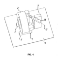
- the axis of rotation 19 lies in a plane that perpendicular to the plane of rotation of the vehicle wheel in the shown first position of the bracket 1 and Horizontal plane is inclined backwards.
- the axis of rotation 19 is inclined at an angle of 45 ° to the horizontal.
- the axes of rotation of the rollers 5 are horizontal and parallel aligned to the vertical plane determined by the axis of rotation 19.
- the vehicle wheel 2 is in the for Appropriate counterweights suitable vertical Location.
- the axis of rotation 19 of the rotary bearing 18 can deviate from that in Figure 4 example also have other layers and be inclined at a different angle. Furthermore, a vertical plane determined by the axis of rotation 19 with respect to the position of the bracket 1 shown in Figure 4 in each any angle between 0 ° and 90 ° to the axis of rotation of the Rollers 5 may be arranged. Also the angle of rotation for rotation the bracket 1 in the second position may vary desired position of the vehicle wheel 2 dimensioned differently his.
Landscapes
- Physics & Mathematics (AREA)
- General Physics & Mathematics (AREA)
- Testing Of Balance (AREA)
Applications Claiming Priority (2)
| Application Number | Priority Date | Filing Date | Title |
|---|---|---|---|
| DE10000683 | 2000-01-10 | ||
| DE2000100683 DE10000683A1 (de) | 2000-01-10 | 2000-01-10 | Vorrichtung zum Auswuchten eines Fahrzeugrades |
Publications (2)
| Publication Number | Publication Date |
|---|---|
| EP1116944A2 true EP1116944A2 (fr) | 2001-07-18 |
| EP1116944A3 EP1116944A3 (fr) | 2002-08-28 |
Family
ID=7627087
Family Applications (1)
| Application Number | Title | Priority Date | Filing Date |
|---|---|---|---|
| EP01100232A Withdrawn EP1116944A3 (fr) | 2000-01-10 | 2001-01-03 | Dispositif d'équilibrage d'une roue de véhicule |
Country Status (3)
| Country | Link |
|---|---|
| EP (1) | EP1116944A3 (fr) |
| BR (1) | BR0100037A (fr) |
| DE (1) | DE10000683A1 (fr) |
Cited By (3)
| Publication number | Priority date | Publication date | Assignee | Title |
|---|---|---|---|---|
| DE10245519A1 (de) * | 2002-09-27 | 2004-04-08 | Schenck Rotec Gmbh | Unwuchtausgleichsstation für Fahrzeugräder |
| DE102007024753A1 (de) * | 2007-05-26 | 2008-11-27 | Bayerische Motoren Werke Aktiengesellschaft | Verfahren zum Aussortieren fehlerhaft montierter Fahrzeugreifen |
| EP3476778B1 (fr) * | 2017-10-27 | 2020-09-02 | Gawronski GmbH | Dispositif et procédé destinés à la manipulation de pneumatiques |
Citations (2)
| Publication number | Priority date | Publication date | Assignee | Title |
|---|---|---|---|---|
| US2117073A (en) * | 1935-07-15 | 1938-05-10 | Bear Mfg Co | Wheel balancing mechanism |
| EP1111362A2 (fr) * | 1999-12-21 | 2001-06-27 | Hofmann Maschinen- und Anlagenbau GmbH | Procédé et dispositif de montage d'un poids de compensation de balourd par un robot |
Family Cites Families (8)
| Publication number | Priority date | Publication date | Assignee | Title |
|---|---|---|---|---|
| US3517558A (en) * | 1967-02-20 | 1970-06-30 | Ammco Tools Inc | Wheel support for balancer |
| US5025662A (en) * | 1983-06-10 | 1991-06-25 | Hultberg Richard M | Automotive wheel balancing apparatus and method |
| DK423488D0 (da) * | 1988-07-29 | 1988-07-29 | Arne Hjorth Hansen | Apparat til af- og paamontering af hjuldaek, navnlig store daek |
| DE3908866A1 (de) * | 1988-09-28 | 1990-03-29 | Dynabal Corp | Dateneingabevorrichtung fuer eine auswuchtmaschine |
| ES2113516T3 (es) * | 1992-02-20 | 1998-05-01 | Interbalco Ag | Aparato para el equilibrado de ruedas. |
| DK44893D0 (da) * | 1993-04-21 | 1993-04-21 | Hjort Hansen Arne | Apparat til af- og paamontering af hjuldaek, navnlig store daek |
| IT1279920B1 (it) * | 1995-03-31 | 1997-12-18 | Corghi Spa | Metodo e apparecchio per equilibrare ruote di veicoli mediante pesi compensatori |
| DE19611574C1 (de) * | 1996-03-23 | 1997-05-07 | Continental Ag | System zum industriellen Auswuchten insbesondere größerer Serien von Kraftfahrzeugrädern |
-
2000
- 2000-01-10 DE DE2000100683 patent/DE10000683A1/de not_active Withdrawn
-
2001
- 2001-01-03 EP EP01100232A patent/EP1116944A3/fr not_active Withdrawn
- 2001-01-09 BR BR0100037A patent/BR0100037A/pt not_active Application Discontinuation
Patent Citations (2)
| Publication number | Priority date | Publication date | Assignee | Title |
|---|---|---|---|---|
| US2117073A (en) * | 1935-07-15 | 1938-05-10 | Bear Mfg Co | Wheel balancing mechanism |
| EP1111362A2 (fr) * | 1999-12-21 | 2001-06-27 | Hofmann Maschinen- und Anlagenbau GmbH | Procédé et dispositif de montage d'un poids de compensation de balourd par un robot |
Cited By (8)
| Publication number | Priority date | Publication date | Assignee | Title |
|---|---|---|---|---|
| DE10245519A1 (de) * | 2002-09-27 | 2004-04-08 | Schenck Rotec Gmbh | Unwuchtausgleichsstation für Fahrzeugräder |
| WO2004031717A1 (fr) * | 2002-09-27 | 2004-04-15 | Schenck Rotec Gmbh | Station d'equilibrage de roues equipee d'un dispositif de serrage basculant |
| US7377165B2 (en) | 2002-09-27 | 2008-05-27 | Schenck Rotek Gmbh | Wheel-balancing station comprising a tiltable clamping device |
| CN100557396C (zh) * | 2002-09-27 | 2009-11-04 | 申克罗泰克有限责任公司 | 带有可倾斜的夹紧装置的车轮平衡台 |
| KR100944321B1 (ko) * | 2002-09-27 | 2010-03-03 | 솅크 로텍 게엠베하 | 경사질 수 있는 클램핑 장치를 가진 휠 밸런싱 스테이션 |
| DE102007024753A1 (de) * | 2007-05-26 | 2008-11-27 | Bayerische Motoren Werke Aktiengesellschaft | Verfahren zum Aussortieren fehlerhaft montierter Fahrzeugreifen |
| DE102007024753B4 (de) * | 2007-05-26 | 2009-05-07 | Bayerische Motoren Werke Aktiengesellschaft | Verfahren zum Prüfen fehlerhaft montierter Fahrzeugreifen |
| EP3476778B1 (fr) * | 2017-10-27 | 2020-09-02 | Gawronski GmbH | Dispositif et procédé destinés à la manipulation de pneumatiques |
Also Published As
| Publication number | Publication date |
|---|---|
| BR0100037A (pt) | 2001-10-30 |
| DE10000683A1 (de) | 2001-07-12 |
| EP1116944A3 (fr) | 2002-08-28 |
Similar Documents
| Publication | Publication Date | Title |
|---|---|---|
| DE69427773T2 (de) | Laufband mit zwei in entgegengesetzter richtung laufenden bändern | |
| DE2919494C2 (de) | Trainingsgerät mit zwei von einem Ständer getragenen Tretkurbeln | |
| DE69115913T2 (de) | Golftrainingsgerät | |
| DE19611130A1 (de) | Vorrichtung zur Erzeugung einer definierten Positionierung und Orientierung mindestens einer Plattform | |
| DE2434716A1 (de) | Ballwurfgeraet | |
| EP0202399B1 (fr) | Support d'appareil d'observation optique | |
| EP0366878A1 (fr) | Table d'opération | |
| EP0129157A2 (fr) | Bras de robot | |
| DE19963965B4 (de) | Zweiteiliges Snowboard zur gesteuerten Fortbewegung auf Schnee und anderen gleitfähigen Medien | |
| EP0173129B1 (fr) | Appareil d'entraînement pour la boxe | |
| DE19503139B4 (de) | Schlagzeugvorrichtung | |
| DE4323315A1 (de) | Bearbeitungsgerät für die Tiefenlockerung von Böden | |
| EP0678443B1 (fr) | Train de roulement, notamment pour machines de travail mobiles et véhicules | |
| DE3445055C2 (fr) | ||
| EP1116944A2 (fr) | Dispositif d'équilibrage d'une roue de véhicule | |
| DE7540045U (de) | Antriebseinheit fuer einen manipulatorarm | |
| DE3644199A1 (de) | Vorrichtung zum reflektieren eines spielballes, insbesondere eines tennis - oder tischtennisballes | |
| DE19807197C1 (de) | Bewegungssystem | |
| DE3831275C2 (fr) | ||
| DE3244833A1 (de) | Turngeraet | |
| DE2418154C2 (de) | Schlepperbetriebene Anbau-Mähmaschine | |
| DE102004059574A1 (de) | Trainingsgerät, insbesondere Crosswalker | |
| DE3412755C2 (de) | Ausfahrbares Fahrwerk für einen Standkörper | |
| EP1362772B1 (fr) | Véhicule pour retourner un silo de compost | |
| EP0991505A1 (fr) | Dispositif pour equilibrer le poids des bras d'un robot |
Legal Events
| Date | Code | Title | Description |
|---|---|---|---|
| PUAI | Public reference made under article 153(3) epc to a published international application that has entered the european phase |
Free format text: ORIGINAL CODE: 0009012 |
|
| AK | Designated contracting states |
Kind code of ref document: A2 Designated state(s): AT BE CH CY DE DK ES FI FR GB GR IE IT LI LU MC NL PT SE TR |
|
| AX | Request for extension of the european patent |
Free format text: AL;LT;LV;MK;RO;SI |
|
| PUAL | Search report despatched |
Free format text: ORIGINAL CODE: 0009013 |
|
| AK | Designated contracting states |
Kind code of ref document: A3 Designated state(s): AT BE CH CY DE DK ES FI FR GB GR IE IT LI LU MC NL PT SE TR |
|
| AX | Request for extension of the european patent |
Free format text: AL;LT;LV;MK;RO;SI |
|
| 17P | Request for examination filed |
Effective date: 20021122 |
|
| AKX | Designation fees paid |
Designated state(s): AT BE CH CY DE DK ES FI FR GB GR IE IT LI LU MC NL PT SE TR |
|
| 17Q | First examination report despatched |
Effective date: 20080624 |
|
| STAA | Information on the status of an ep patent application or granted ep patent |
Free format text: STATUS: THE APPLICATION IS DEEMED TO BE WITHDRAWN |
|
| 18D | Application deemed to be withdrawn |
Effective date: 20081105 |