EP1116955A2 - Systhème interactif de diagnose - Google Patents
Systhème interactif de diagnose Download PDFInfo
- Publication number
- EP1116955A2 EP1116955A2 EP01200566A EP01200566A EP1116955A2 EP 1116955 A2 EP1116955 A2 EP 1116955A2 EP 01200566 A EP01200566 A EP 01200566A EP 01200566 A EP01200566 A EP 01200566A EP 1116955 A2 EP1116955 A2 EP 1116955A2
- Authority
- EP
- European Patent Office
- Prior art keywords
- computer
- sensors
- actuators
- auto
- arrangement
- Prior art date
- Legal status (The legal status is an assumption and is not a legal conclusion. Google has not performed a legal analysis and makes no representation as to the accuracy of the status listed.)
- Withdrawn
Links
- 230000002452 interceptive effect Effects 0.000 title abstract description 9
- 230000006870 function Effects 0.000 claims description 25
- 238000012544 monitoring process Methods 0.000 claims description 23
- 230000000295 complement effect Effects 0.000 claims description 4
- 238000000034 method Methods 0.000 claims 9
- 238000002405 diagnostic procedure Methods 0.000 abstract description 6
- QVGXLLKOCUKJST-UHFFFAOYSA-N atomic oxygen Chemical compound [O] QVGXLLKOCUKJST-UHFFFAOYSA-N 0.000 description 34
- 229910052760 oxygen Inorganic materials 0.000 description 34
- 239000001301 oxygen Substances 0.000 description 34
- 238000012360 testing method Methods 0.000 description 26
- 239000000446 fuel Substances 0.000 description 10
- 238000005516 engineering process Methods 0.000 description 4
- 238000002347 injection Methods 0.000 description 3
- 239000007924 injection Substances 0.000 description 3
- 230000007246 mechanism Effects 0.000 description 3
- 230000002159 abnormal effect Effects 0.000 description 2
- 238000010586 diagram Methods 0.000 description 2
- 206010000117 Abnormal behaviour Diseases 0.000 description 1
- 230000009471 action Effects 0.000 description 1
- 238000013459 approach Methods 0.000 description 1
- 230000005540 biological transmission Effects 0.000 description 1
- 238000002485 combustion reaction Methods 0.000 description 1
- 238000013461 design Methods 0.000 description 1
- 238000003745 diagnosis Methods 0.000 description 1
- 125000000524 functional group Chemical group 0.000 description 1
- 238000011990 functional testing Methods 0.000 description 1
- 230000004044 response Effects 0.000 description 1
- 230000000979 retarding effect Effects 0.000 description 1
- 238000013519 translation Methods 0.000 description 1
Images


Classifications
-
- G—PHYSICS
- G01—MEASURING; TESTING
- G01R—MEASURING ELECTRIC VARIABLES; MEASURING MAGNETIC VARIABLES
- G01R31/00—Arrangements for testing electric properties; Arrangements for locating electric faults; Arrangements for electrical testing characterised by what is being tested not provided for elsewhere
- G01R31/36—Arrangements for testing, measuring or monitoring the electrical condition of accumulators or electric batteries, e.g. capacity or state of charge [SoC]
- G01R31/3644—Constructional arrangements
- G01R31/3648—Constructional arrangements comprising digital calculation means, e.g. for performing an algorithm
-
- G—PHYSICS
- G01—MEASURING; TESTING
- G01R—MEASURING ELECTRIC VARIABLES; MEASURING MAGNETIC VARIABLES
- G01R31/00—Arrangements for testing electric properties; Arrangements for locating electric faults; Arrangements for electrical testing characterised by what is being tested not provided for elsewhere
- G01R31/005—Testing of electric installations on transport means
- G01R31/006—Testing of electric installations on transport means on road vehicles, e.g. automobiles or trucks
- G01R31/007—Testing of electric installations on transport means on road vehicles, e.g. automobiles or trucks using microprocessors or computers
-
- G—PHYSICS
- G07—CHECKING-DEVICES
- G07C—TIME OR ATTENDANCE REGISTERS; REGISTERING OR INDICATING THE WORKING OF MACHINES; GENERATING RANDOM NUMBERS; VOTING OR LOTTERY APPARATUS; ARRANGEMENTS, SYSTEMS OR APPARATUS FOR CHECKING NOT PROVIDED FOR ELSEWHERE
- G07C5/00—Registering or indicating the working of vehicles
- G07C5/08—Registering or indicating performance data other than driving, working, idle, or waiting time, with or without registering driving, working, idle or waiting time
- G07C5/0808—Diagnosing performance data
-
- G—PHYSICS
- G01—MEASURING; TESTING
- G01R—MEASURING ELECTRIC VARIABLES; MEASURING MAGNETIC VARIABLES
- G01R31/00—Arrangements for testing electric properties; Arrangements for locating electric faults; Arrangements for electrical testing characterised by what is being tested not provided for elsewhere
- G01R31/005—Testing of electric installations on transport means
Definitions
- the present invention relates generally to a diagnostic system for an automotive vehicle of the type having (1) a network of sensors and actuators for independently sensing and actuating a number of different functions within the vehicle and (2) an onboard computer for monitoring the sensors and controlling the operation of the actuators.
- the present invention relates more particularly to what may be referred to as an interactive system for diagnosing the performance of a vehicle (1) by controlling the operation of one or more of its specific actuators independent of its onboard computer, (2) by simulating the operation of one or more of its specific sensors independent of the actual operation of those sensors, and (3) by continuously monitoring and analyzing the other vehicle actuators and sensors and, in fact, all of the electronic data entering and/or exiting the onboard computer, preferably, in real time.
- a typical vehicle manufactured today includes an onboard computer 10 which is generally referred to as an electronic control module.
- This ECM serves to control the operation of one or more specific actuators associated with the vehicle's auto drive system 12 including its engine and other components by responding to the network of corresponding sensors.
- Typical actuators which are usually solenoids, although not always, might include fuel injectors, an air diverter valve, an ignition module, valves associated with anti-lock brakes, as well as others, some of which are illustrated in Figure 1.
- Typical sensors may include temperature sensors, oxygen level sensors, sensors associated with anti-lock brakes and so on, some of which are also illustrated in Figure 1.
- the way in which these components interrelate with one another and with the electronic control module may be best exemplified by the way in which fuel injection is controlled as a function of oxygen levels within the engine. More specifically, the ECM uses an oxygen sensor in the exhaust manifold to sense the oxygen level there and, at the same time, it operates the fuel injector through an associated solenoid. Thus, if the ECM senses an increase in oxygen, it will automatically increase fuel consumption by appropriately operating the fuel injection solenoid and, if it senses a decrease in oxygen, it will automatically decrease fuel consumption by means of the same solenoid, thus achieving optimal emission levels.
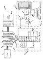
- FIG. 1 a typical arrangement 14 for electrically connecting the ECM 10 with its network of actuators and sensors 12 is illustrated.
- This connection arrangement includes an auto-side connector 16 having a series of auto-side plug-in terminals 18 respectively connected with associated sensors and actuators and a computer-side connector 20 disengageably connectable to the auto-side connector by means of corresponding, complementary computer-side plug-in terminals 22 connected to the appropriate circuitry within electronic control module 10.
- the auto-side terminals 18 are shown as the male terminals and the computer-side terminals 22 are shown as female terminals.
- cooperating terminals 18, 22 are designated T1, T2, T3 and so on.
- the oxygen sensor might be associated with terminal T1 in one vehicle and T5 in another.
- Vehicle makes and models may include sensors and actuators that other vehicle makes and models do not have.
- a knock sensor used to sense engine knocks, which result in the ECM retarding spark timing, is found generally only in more expensive cars.
- the automotive service professional might use what is commonly referred to as a "breakout box", generally indicated by the reference numeral 24, for gaining access to all of the terminals T1-T10.
- the breakout box has its own adaptor 26 disposed between and connecting together auto-side connector 16 with computer-side connector 20 such that each terminal 18 remains connected to its associated terminal 22.
- adaptor 26 is connected to the breakout box through a connecting harness 28 for electrically connecting the breakout box's own terminals 30 to corresponding terminals Tl, T2, T3 and so on.
- the automotive service professional can easily gain access to any of the terminals T1 - T10 by means of terminals 30.
- the breakout box 24 is typically used by the automotive service professional to diagnose a problem associated with energization of a trouble light on the dashboard of the vehicle in question.
- Many vehicle makes and models include their own trouble code associated with each given trouble light.
- a trouble code indicates some abnormal condition in a given circuit within the vehicle's electronic system.
- trouble code 42 on a GM vehicle may indicate abnormal voltage readings from the oxygen sensor.
- a professional may connect the breakout box 24 and insert a voltmeter into the terminal associated with the oxygen sensor on that particular vehicle, say terminal T 5 , and verify the actual voltage in the circuit. It is worthwhile noting that whereas some trouble codes are very specific, others are quite general and in many cases the same code will be set for many different problems; further more, many problems will cause the setting of multiple trouble codes.
- the diagnostic system associated with the breakout box 24, as described above, is a passive system. That is, the automotive service professional uses the breakout box to access the connector terminals in order to observe the components associated with those terminals typically by connecting a volt meter and from those observations, he is hopefully able to diagnose the problem.
- a more particular object of the present invention is to provide a diagnostic work station which utilizes its own external computer for continuously monitoring, preferably in real time, and analyzing electronic data entering and/or exiting the onboard computer of the vehicle being diagnosed including actual data associated with the vehicle's network of sensors and actuators.
- Another particular object of the present invention is to provide a state-of-the-art diagnostic work station that takes an interactive role, which means that it is not only capable of analyzing the electronic data entering and/or exiting the onboard computer, but it is also capable of controlling the operation of one or more specific actuators independent of the onboard computer and simulating the operation of one or more specific sensors, independent of the actual operation of these sensors, as contrasted with the previously described breakout box 24 which merely takes a passive role.
- Still another particular object of the present invention is to provide a state-of-the-art diagnostic work station that is rapidly and easily adapted for use with different vehicle makes and models.
- the particular diagnostic work station, actually system, disclosed herein is specifically designed for high technology automotive vehicles of the type described in conjunction with Figure 1.
- a vehicle including (1) a network of sensors and actuators for independently sensing and actuating a number of different functions within the vehicle, (2) an onboard computer for monitoring the sensors and controlling operation of the actuators, and (3) cooperating auto-side and computer-side connectors having cooperating auto-side and computer-side plug-in terminals for electrically connecting the onboard computer with the sensors and actuators, again as described previously in conjunction with Figure 1.
- This application is a divisional from EPA No. 92906083.8.
- the particular diagnostic work station disclosed herein utilizes means including its own computer arrangement separate from the vehicle's onboard computer, for continuously monitoring and analyzing in real time electronic data entering and/or exiting the onboard computer, that is, the ECM, including actual data associated with the vehicle's network of sensors and actuators.
- the ECM electronic data entering and/or exiting the onboard computer
- the monitor in association with the external computer arrangement, the outputs of a number of related sensors can be simultaneously observed visually while, at the same time, the operation of associated actuators are monitored.
- the diagnostic work station disclosed herein includes a series of components that cooperate with its external computer for allowing the work station to interact directly with the vehicle's network of sensors and actuators and its onboard computer. This is accomplished first by providing suitable means for selectively and temporarily disconnecting one or more specific sensors and/or one or more specific actuators from the vehicle's onboard computer. At the same time, the work station's external computer arrangement is temporarily connected with these latter sensors for simulating the action of each one independent of its actual operation and also connected to these latter actuators for controlling the operation of each of these actuators independent of the onboard computer.
- some of the other sensors and actuators that is, those not disconnected from the vehicle's onboard computer, can be continuously monitored and analyzed by the external computer.
- the diagnostic work station disclosed herein it is not necessary to move the vehicle to a location of high altitude or to subject the vehicle to high or low temperature conditions. Rather, all that is necessary is to disconnect the appropriate barometric and temperature sensors from the vehicle's onboard computer and, using the external computer arrangement, simulate the way the sensors would operate at high altitude and at high or low temperature conditions so that the onboard computer thinks these latter conditions exist. The onboard computer will then operate the rest of the vehicle functions as if that were the case and these latter functions can then be monitored and analyzed by the external computer under these simulated conditions.
- the diagnostic work station disclosed herein merely serves a passive role of continuously monitoring and analyzing the vehicle in question or actually interacts with the vehicle, as described briefly above, it is readily and rapidly adaptable for use with vehicles of different makes and models. This is because, although different vehicle makes and models include different sensors and/or actuators and different onboard computers, the work station's external computer is provided with a database for distinguishing between these differences.
- Figure 2 illustrates a diagnostic work station 32 which is designed in accordance with the present invention to provide automotive service professionals with all the tools necessary to perform precision diagnostic testing on today's high technology vehicles.
- vehicle 34 includes among other components, an entire auto-drive system 35 which itself includes an engine, transmission, brakes, and so on, as well as a network of sensors and actuators associated with these latter components.
- the sensors and actuators are indicated by the letters S and A with numerical subscripts distinguishing one from the other.
- Vehicle 34 also includes an onboard computer, specifically the same electronic control module 10 and arrangement 14 for electrically connecting the ECM with the sensors and actuators as described in conjunction with Figure 1.
- arrangement 14 includes an auto-side connector 16 having its own auto-side plug-in terminals 18 and a computer-side connector 20 including its own computer-side plug-in terminals 22.
- terminals T1-T10 For purposes of convenience, only ten terminals are illustrated, specifically terminals T1-T10. Most of these terminals connect associated sensors or actuators with appropriate circuitry at ECM 10.
- terminal T1 connects ECM 10 with sensor S1
- terminal T2 connects the ECM to sensor S2, and so on.
- the particular components M7 and G8 illustrated as part of the auto-drive system and connected to the ECM through terminals T7 and T8 will be described hereinafter along with the function of terminal T9.
- diagnostic work station 32 This work station includes its own external computer arrangement 36 which, as will be discussed in more detail below, is specifically designed for three primary purposes. First, it is designed to control the operation of one or more specific actuators independent of one another and independent of the onboard ECM 10. Second, it is designed to simulate the operation of one or more specific sensors, independent of one another and independent of their actual operation. Third, computer arrangement 36 is designed to continuously monitor and analyze in real time all of the electronic data entering and exiting ECM 10 including actual data associated with the network of sensors and actuators.
- work station 32 also includes an arrangement 38 which also serves a number of purposes.
- arrangement 38 serves to selectively and temporarily disconnect one or more specific sensors and/or actuators from ECM 10.
- arrangement 38 serves to connect external computer arrangement 36 to those actuators that have been temporarily disconnected from ECM 10 so that the external computer arrangement can override the ECM and control those actuators.
- arrangement 38 serves to connect the external computer arrangement 36 into the circuitry of ECM 10 associated with those sensors that have been temporarily disconnected in order to simulate the operation of those sensors.
- arrangement 38 serves to connect external computer arrangement 36 to ECM 10 for monitoring the data entering and/or leaving the ECM, that is, the data passing between the ECM and various vehicle drive system components.
- actuator A6 for example, actuator A6
- sensors S3 and S4 it can also monitor the other actuators and sensors, that is, those actuators and sensors that remain connected to the ECM.
- the ECM By modulating this signal in the same way as the actual sensor S4 would, the ECM can be made to believe that the engine itself is varying in temperature causing it to vary the ignition timing accordingly. As a result, the vehicle's advance-retard angle can be observed as a function of temperature without ever leaving the service garage.
- computer arrangement 36 takes over control of certain actuators and simulates certain sensors to make ECM 10 think that the vehicle is under a load. At the same time, it continuously monitors the valve in question in order to see if it actually does open the proper way under this load.
- computer arrangement 36 it is also possible to use computer arrangement 36 to directly control the EGR value, by disconnecting it from ECM 10, and driving it to open, simultaneously monitoring other vehicle conditions such as temperature and fuel modulation in order to discern whether the value is operating properly.
- work station 32 may be used solely for monitoring and analyzing certain vehicle functions without any interactive role at all.
- An example of this might be the vehicle's cruise control. Since the cruise control is not critical to the vehicle's operation, it may be desirable, from an economic standpoint, to provide the work station without means for interacting with the cruise control. In this case, the cruise control would be connected to computer arrangement 36 in a "monitor only" mode, in which case, the computer arrangement can still analyze operation of the cruise control and not directly affect its operation.
- work station 32 In a most economical version of work station 32, it would be designed only to continuously monitor and analyze in real time electronic data entering and exiting the ECM without any interactive roles at all.
- the work station serves as a highly sophisticated analytical tool far superior to the breakout box illustrated in Figure 1, but would have less diagnostic capability than the interactive work station illustrated in Figure 2.
- FIG. 2 this latter arrangement including what may be referred to as a pod 40 which is comprised of a series of lines or channels C1, C2 and so on, include electronic switching circuits to be described below.
- This pod is disengageably connectable to a vehicle adaptor 42 by means of their respective plug-in cable harnesses 44 and 46.
- Adaptor 42 is comprised of its own auto-side connector 48 and its own computer-side connector 50, each of which includes its own plug-in terminals complementary to plug-in terminals 18 and 22. In this way the connectors 16 and 48 and the connectors 20 and 50 can be respectively connected together.
- the connectors 16 and 20 may differ for different vehicle makes and models and, hence, different adapters must be used.
- the terminal T1 associated with the sensor S1 is connected to Channel C1.
- the terminal T1 may be associated with different drive system component, for example, sensor S4, and might therefore be connected through the cooperating adaptor to Channel C 4 for example.
- each adapter has its own unique way of connecting terminals T1, T2 and so on with channel lines C1, C2 and so on.
- pod 40 is comprised of a series of electronic switching circuits which may be readily provided by those with ordinary skill in the art. However, for purposes of simplicity, these switching circuits are depicted in Figure 2 as simple mechanical switches and will be referred to herein as either switches or switching circuits. It is important to note that there are three different sets of switching circuits which perform three different functions. There is a first set of switching circuits generally represented by the switches S1, S2, S3 and so on. A second set is indicated at S'1, S'2 and so on, while a third set is shown at S"5, S"6, S"8 and S"10. The function of each set will be described below.
- Switches S1, S2, S3 and so on function to selectively connect or disconnect corresponding auto-side terminals 18 to or from associated computer-side terminals 22.
- the switch S1 on channel line C1 is shown in its closed condition, thereby connecting the T1 terminal 18 to the T1 terminal 22.
- This will electrically connect the sensor S1 to its associated circuitry in ECM 10 through the plug-in terminals T1.
- switch S2 on channel line C2 which maintains sensor S2 connected to ECM 10.
- sensors S3 and S4 are shown in an opened condition, thereby disconnecting the T3 and T4 terminals 18 from the T3 and T4 terminals 22 which, in turn, disconnect sensors S3 and S4 from ECM 10.
- switches S6 is open, switches S5 and S10 are closed, and there are no switches S associated with channel lines C7, C8 and C9.
- the C7 channel line which is a monitor only line as described above, may be connected to, for example, the connector terminals associated with the vehicle's cruise control. In this way, computer arrangement 36 can monitor and analyze the cruise control but it cannot interact with it.
- the C9 line in Figure 2 is actually provided to symbolically represent a series of lines for monitoring all of the other lines. This is more realistically depicted in Figure 3, as will be seen.
- the C8 line will be discussed hereinafter.
- the second series of switches, S'1, S'2 and so on, serve to connect corresponding computer-side terminals 22 to the sensor simulating circuitry 56 within computer arrangement 36 while the third series of switches S"5, S"6 and S"8 serve to connect the corresponding auto-side terminals 18 to the actuator driving circuit 56 within computer arrangement 36.
- switch S'l is shown opened and therefore assures that the circuitry within the ECM 10 and connected to the T1 computer-side terminal 22 is not driven by external computer arrangement 36.
- switching circuit S'3 connects computer arrangement 36 to the circuitry in ECM 10 associated with sensor S3 through the T3 computer-side terminal 22.
- switching circuit S"6 is closed and therefore connects actuator A6 with computer arrangement 36 through the T6 terminal 18.
- channel line C8 the status of the other switching circuits should be self explanatory from Figure 2 and the discussion immediately above.
- the switching circuits S' are associated with sensors and thus connect the computer arrangement 36 to ECM 10 while the switching circuits S" are associated with actuators and hence connect computer arrangement 36 to the actuators.
- line C 8 it should be noted that it includes both an S' and an S" switching circuit. This is because the C 8 line serves to test the ground lines in the entire vehicle system. By closing the switch S'8, the ground lines in the ECM 10 can be resistance tested by injecting a known current into the line and measuring the resultant voltage. This is also true for the ground lines of the vehicle drive system side by closing the switch S"8. While only one such line C8 is shown, there are usually a number of such lines.
- this arrangement includes its own CPU 52 which can be, for example, part of a readily providable personal computer including an associated monitor 54 and keyboard 55.
- the arrangement also provides a suitable and readily providable interface between the computer including the necessary digital/analog converters one of which is generally indicated at 56 and analog/digital converters generally indicated at 58.
- the digital/analog converters 56 allow CPU 52 to drive (actually control the operation of) particular vehicle actuators through switching circuits S" and simulate particular sensors feeding into circuitry within the ECM 10 through cooperating switching circuits S'.
- the analog/digital converters allow the external CPU 52 to "listen to", that is, monitor data entering and leaving ECM 10.
- one or more A/D converters can be used for listening to all the terminal lines utilizing a suitable and readily providable sweep mechanism which is operated in a time slicing mode.
- some of the D/A converters associated with actuators are actually driver circuits including on-off switches.
- channels C1-C10 in pod 40 connect to A/D circuitry 58 through a conventional and readily providable multiplexer 59 forming part of the sweep mechanism just mentioned so that individual terminal lines and specific groups of terminal lines can be scanned by the CPU.
- CPU 52 may be part of any suitable and readily providable computer, for example a standard personal computer.
- the software used to run the computer represented generally by the diagrammatically depicted look up table 60 or menu, is also readily providable by those with ordinary skill in the art in view of the teachings herein.
- the software must be designed to control the various actuators in the intended manner and simulate the various sensors. It also must have the ability to analyze the various data presented to the external computer.
- a particular feature of work station 32 resides in a specific software database maintained within CPU 52.
- different vehicle makes and/or models compatible with work station 32 may include different sensors or actuators, different onboard computers and/or a different arrangement of auto-side and computer-side terminals.
- external CPU 52 includes a database for distinguishing between any of these differences in different vehicle makes and models.
- the automotive service professional can easily enter the appropriate vehicle identification into CPU 52 using keyboard 55 and provide the appropriate adaptor 32 in order to make the work station compatible with the particular vehicle in question.
- the database also includes performance information pertaining to specific sensors and actuators for particular vehicle makes and models.
- the CPU and its software include suitable and readily providable means for storing electronic data presented to it into memory, a database having exemplary data associated with the networks of sensors and actuators, and means for comparing the actual data stored in memory with the exemplary data.
- the CPU and its software also include suitable and readily providable means for carrying out different diagnostic tests by operating certain specific actuators and simulating certain specific sensors in a predetermined way.
- Software menu 60 is shown specifically including an "AUTO SELECT" item which represents a data base for distinguishing between vehicle makes and models.
- the T1-T10 items represent data associated with the sensors, actuators and other components connected with connector terminals T1 - T10. As stated above, this data varies with the particular vehicle selected and would include for certain components the desired performance criteria to be used as a reference against actual performance data.
- the items labeled "Test No. 1", “Test No. 2" and so on refer to a data base for carrying out different predetermined diagnostic tests.
- the menu 60 illustrated in Figure 2 is by no means complete, nor is it intended to be complete. It is provided rather as an example of the necessary software required to operate CPU 52 in the desired manner, which software is readily providable, as indicated above. A more detailed discussion of the way in which the overall work station operates from a software standpoint will follow.
- the terminal lines associated with terminals T1 and T2 are shown as monitoring lines and, hence, include no switching circuits at all.
- the terminal lines associated with terminals T3, T4 and T5 do include switching circuits.
- a single switching circuit is used to combine the function of the previously described switches S and S' or S".
- a single switching circuit S w 3 is used to connect the auto-side and ECM side terminals T3 to one another and alternatively to connect the ECM side terminal T3 to D/A circuitry within computer arrangement 36. This is also the case for switching circuit S w 4.
- the terminal line T5 includes a switching circuit Sw5 which in one position connects together the ECM side and auto-side terminals T5 and in the opposite position connects computer arrangement 36, actually its driver circuit 56, to the auto-side terminal T5 for connection with the associated actuator A5.
- a switching circuit Sw5 which in one position connects together the ECM side and auto-side terminals T5 and in the opposite position connects computer arrangement 36, actually its driver circuit 56, to the auto-side terminal T5 for connection with the associated actuator A5.
- driver circuits including on/off switches rather than through D/A converters.
- any given actuator is always driven by the external computer in a way which is consistent with the actuator's electrical properties, i.e., voltage, current, impedance, etc.
- a solenoid requires different drive parameters than a stepper monitor.
- monitoring lines T1 and T2 in Figure 3 are shown including A/D converters but all of the other lines, that is, those including switching circuits also include A/D converters which serve to monitor or listen to those lines, regardless of the position of any given switching circuit. In this latter regard, in actual practice, it may be desirable to include a single A/D converter for listening purposes along with a sweep mechanism operated in a time slice mode.
- the data base is composed of various tables as shown in Figure 4, as follows: Component Table: For every component used with any vehicle, there is an entry in this table. Every entry contains the component identification (ID), type (sensor, thermistor, solenoid, etc.) and electrical parameters (min-max volts, resistance, inductance, translation tables to physical units, etc.).
- Component Table For every channel C1, C2 and so on in the pod there is an entry in this table. Every entry contains the channel mux-address, the switch address, the D/A address, and other electrical parameters (i.e. gain, impedence, drive capabilities, etc.). 2.
- CONNECTOR TABLE For every ECM used in any vehicle, there is an entry in this table describing the vehicle connector 14 (see Figure 1). Every entry is itself a table with an entry for every terminal on the particular ECM. Every terminal entry contains the terminal name (e.g., T1, T2), the component connected to this terminal, and the channel C1, C2, and so on, through which this terminal is routed in pod 40.
- Engine Table For every engine used in any vehicle there is an entry in this table containing the vehicle ID number (VIN), general engine information (i.e., number of cylinders, ignition type, injection type, etc.) and the ID of the connector for this engine.
- VIN vehicle ID number
- general engine information i.e., number of cylinders, ignition type, injection type, etc.
- the first example will be what is called a sweep test, invoked by say item Test No. 1 in menu 60 of Fig. 2.
- the sweep test is a software function that examines all terminals of a given vehicle sequentially, monitoring them under known conditions for abnormal behavior.
- the second example to be discussed is a functional bypass test, invoked say by item Test No. 5 of menu 60, Fig. 2.
- a functional test will look at a group of terminals simultaneously, examining a particular correlation in their operation.
- Sweep tests are divided into functional groups: key off, key on-engine off, cranking and engine running tests.
- Key Off Tests These tests look at all power ground lines.
- a software function scans the connector table for the vehicle (Fig. 4) searching for those terminals connected to a component of the type "POWER" or "GROUND", as contained in the component information pointed at through the connector table. For every power terminal, the voltage is read from the appropriate channel and compared to the nominal values of the matching component in the DB. For every ground terminal, voltage is read and compared as above, then the appropriate switch S" is turned on, routing that channel to one of the D/A's. The particular D/A is then driven by software to inject a known current into the line connected to the terminal on the car side.
- Voltage drop is read from the appropriate channel and line resistance is computed and compared to the DB values.
- Key on-Engine Off These tests look at all sensors and actuators. For every sensor, voltage is read from the appropriate channel and compared to DB values as above. For all solenoids (actuators) voltage and resistance are measured as for ground lines. In addition, when current is injected into a solenoid, the actual current taken by the solenoid is plotted against time, and inductance is computed from this curve, and compared to DB values.
- the vehicle ECM Under constant running conditions (RPM and load) the vehicle ECM will constantly monitor the oxygen sensor output which may be high, indicating high oxygen contentsin the exhaust manifold, or low, indicating low oxygen.
- the ECM responds by modulating the fuel injectors to counter the oxygen readings.
- This scheme is called a negative feedback loop, where injector pulse width is the controlled variable and oxygen is the error signal.
- Test Description While the engine is running, the system 32 will inject a simulated oxygen signal into the ECM.
- the signal is a square wave, with min-max voltage range based on DB values for a given oxygen sensor. While injecting this signal, the system will simultaneously monitor the Injector driver line, computing in real time the variation in injector pulse width, and also the output of the real oxygen sensor.
- Expected Result The correlation between the injected signal and fuel modulation indicates whether or not the ECM is properly responding to variations in oxygen. The skew between the injected oxygen and the real oxygen indicates the time response of the oxygen sensor. For a vehicle without any faults, the schematic results are shown in Figure 5.
- a software function is provided within the system to execute the above test.
- the connector table for the vehicle ( Figure 4) is scanned, searching for the terminals corresponding to the oxygen signal, the injector drivers (one or more) and the tach signal (RPM).
- the oxygen channel switch is configured for bypass into the ECM.
- the appropriate D/A is configured to generate a square wave with min-max voltage equal to nominal values for oxygen from the DB.
- the injector driver, the oxygen sensor and the tach signal are configured for "Read" (to listen) by properly selecting their respective channels in the A/D mux.
- the user is instructed to rev the engine to 2000 RPM, and the test begins:
- the system monitors the tach signal, waiting for 2000 RPM. At that point, the D/A is enabled which causes the simulated signal to be generated.
- the program then monitors simultaneously the simulated value, the real oxygen value and the injector driver.
- the injector signal is converted in real time to a pulse-width value, and is plotted against time together with the other values. This goes on for approximately 15 seconds, at which time bypass is disabled and monitoring stops.
- the final stage is a mathematical computation done on the data recorded in memory. The correlation of simulated oxygen and injector pulse width is computed, and the skew between simulated oxygen and real oxygen is measured. Both values are compared against good known results.
- the present invention is not limited to the particular computer arrangement 36 or the particular connector arrangement 38 illustrated in Figures 2 and 3. Rather, based on the teachings herein, one with ordinary skill in the art can readily modify either of these arrangements so long as they fulfill the functions herein. Moreover, based on the teachings herein, and with suitable and readily providable knowledge about particular automotive vehicles, one with ordinary skill in the software art can readily design the software used to operate computer 52.
- the present invention does not relate to the software per se but rather to the way in which the overall diagnostic station is able to continuously monitor and analyze vehicle 34 and more particularly to the way it is able to take an interactive role in the diagnostic process. In an actual working embodiment, an IBM PC AT or compatible system has been provided. Tables 1-3 forming the Appendix I (pages A1-A20) attached hereto list examples of actual engines, specific functions and tests by the actual embodiment. The present invention contemplates but is not limited to these particular engines, functions and tests.
Landscapes
- Physics & Mathematics (AREA)
- General Physics & Mathematics (AREA)
- Engineering & Computer Science (AREA)
- Combustion & Propulsion (AREA)
- Microelectronics & Electronic Packaging (AREA)
- Chemical & Material Sciences (AREA)
- Computer Hardware Design (AREA)
- Testing And Monitoring For Control Systems (AREA)
- Control Of Electric Motors In General (AREA)
- Testing Or Calibration Of Command Recording Devices (AREA)
- Testing Of Engines (AREA)
- Electric Propulsion And Braking For Vehicles (AREA)
- Vehicle Cleaning, Maintenance, Repair, Refitting, And Outriggers (AREA)
- Automobile Manufacture Line, Endless Track Vehicle, Trailer (AREA)
Applications Claiming Priority (3)
| Application Number | Priority Date | Filing Date | Title |
|---|---|---|---|
| US647774 | 1984-09-06 | ||
| US07647774 US5214582C1 (en) | 1991-01-30 | 1991-01-30 | Interactive diagnostic system for an automobile vehicle and method |
| EP92906083A EP0575399B1 (fr) | 1991-01-30 | 1992-01-29 | Procede et systeme de diagnostic interactif pour une automobile |
Related Parent Applications (1)
| Application Number | Title | Priority Date | Filing Date |
|---|---|---|---|
| EP92906083A Division EP0575399B1 (fr) | 1991-01-30 | 1992-01-29 | Procede et systeme de diagnostic interactif pour une automobile |
Publications (2)
| Publication Number | Publication Date |
|---|---|
| EP1116955A2 true EP1116955A2 (fr) | 2001-07-18 |
| EP1116955A3 EP1116955A3 (fr) | 2001-10-04 |
Family
ID=24598218
Family Applications (2)
| Application Number | Title | Priority Date | Filing Date |
|---|---|---|---|
| EP01200566A Withdrawn EP1116955A3 (fr) | 1991-01-30 | 1992-01-29 | Systhème interactif de diagnose |
| EP92906083A Expired - Lifetime EP0575399B1 (fr) | 1991-01-30 | 1992-01-29 | Procede et systeme de diagnostic interactif pour une automobile |
Family Applications After (1)
| Application Number | Title | Priority Date | Filing Date |
|---|---|---|---|
| EP92906083A Expired - Lifetime EP0575399B1 (fr) | 1991-01-30 | 1992-01-29 | Procede et systeme de diagnostic interactif pour une automobile |
Country Status (9)
| Country | Link |
|---|---|
| US (1) | US5214582C1 (fr) |
| EP (2) | EP1116955A3 (fr) |
| JP (1) | JP3081243B2 (fr) |
| AT (1) | ATE204990T1 (fr) |
| CA (1) | CA2101336C (fr) |
| DE (1) | DE69232029T2 (fr) |
| DK (1) | DK0575399T3 (fr) |
| ES (1) | ES2163397T3 (fr) |
| WO (1) | WO1992014216A1 (fr) |
Cited By (7)
| Publication number | Priority date | Publication date | Assignee | Title |
|---|---|---|---|---|
| EP1530054A1 (fr) * | 2003-11-08 | 2005-05-11 | Robert Bosch Gmbh | Appareil pour tester l'aptitude à fonctionner d'un composant éléctrique |
| WO2007038983A1 (fr) * | 2005-09-29 | 2007-04-12 | Snap-On Incorporated | Analyse de flux de donnees de diagnostic de vehicule utilisant un film du flux de donnees enregistre |
| WO2014118327A1 (fr) * | 2013-02-01 | 2014-08-07 | Jaguar Land Rover Limited | Procédé et appareil de diagnostic d'un véhicule |
| WO2014118329A1 (fr) * | 2013-02-01 | 2014-08-07 | Jaguar Land Rover Limited | Appareil et procédé de diagnostic de véhicule |
| WO2014118328A1 (fr) * | 2013-02-01 | 2014-08-07 | Jaguar Land Rover Limited | Appareil et procédé de diagnostic de véhicule |
| US9704307B2 (en) | 2013-04-26 | 2017-07-11 | Jaguar Land Rover Limited | Vehicle diagnostics apparatus, diagnostics unit and methods |
| WO2018015083A1 (fr) * | 2016-07-20 | 2018-01-25 | Volkswagen Aktiengesellschaft | Procédé de fonctionnement d'un système de véhicule automobile |
Families Citing this family (241)
| Publication number | Priority date | Publication date | Assignee | Title |
|---|---|---|---|---|
| GB9016533D0 (en) * | 1990-07-27 | 1990-09-12 | Churchill V L Ltd | Automotive diagnostic tool |
| DE4027824C1 (fr) * | 1990-09-01 | 1992-03-12 | Daimler-Benz Aktiengesellschaft, 7000 Stuttgart, De | |
| US5408412A (en) * | 1992-04-09 | 1995-04-18 | United Technologies Corporation | Engine fault diagnostic system |
| US5369392A (en) * | 1992-09-16 | 1994-11-29 | Caterpillar Inc. | Method and apparatus for indicating faults in switch-type inputs |
| US5327344A (en) * | 1992-09-16 | 1994-07-05 | Caterpillar Inc. | Method and apparatus for reconfiguring a computerized monitoring system |
| JPH06206471A (ja) * | 1992-09-16 | 1994-07-26 | Caterpillar Inc | プログラム可能なゲージを有するコンピュータ化監視システム |
| JPH06213061A (ja) * | 1992-09-16 | 1994-08-02 | Caterpillar Inc | 入力を選択的に監視する方法及び装置 |
| JPH06213688A (ja) * | 1992-09-16 | 1994-08-05 | Caterpillar Inc | データを受け取る方法及び装置 |
| US5453939A (en) * | 1992-09-16 | 1995-09-26 | Caterpillar Inc. | Computerized diagnostic and monitoring system |
| JPH06174600A (ja) * | 1992-09-16 | 1994-06-24 | Caterpillar Inc | 状態変化を表示する方法および装置 |
| DE4302482B4 (de) | 1993-01-29 | 2006-04-13 | Robert Bosch Gmbh | Verfahren zur Prüfung eines elektronischen Steuergerätes mit Hilfe eines externen Diagnosegerätes |
| US5631831A (en) * | 1993-02-26 | 1997-05-20 | Spx Corporation | Diagnosis method for vehicle systems |
| JP3388466B2 (ja) * | 1993-03-17 | 2003-03-24 | 株式会社共立 | 計測装置 |
| US5671141A (en) * | 1993-04-05 | 1997-09-23 | Ford Global Technologies, Inc. | Computer program architecture for onboard vehicle diagnostic system |
| US5535620A (en) * | 1993-04-05 | 1996-07-16 | Applied Computer Engineering, Inc. | Engine management system |
| US5463567A (en) * | 1993-10-15 | 1995-10-31 | Caterpillar Inc. | Apparatus and method for providing historical data regarding machine operating parameters |
| US5534856A (en) * | 1993-11-18 | 1996-07-09 | Scully Signal Company | Vehicle identification and verification system |
| FR2713791B1 (fr) * | 1993-12-14 | 1996-02-02 | Aerospatiale | Procédé et dispositif pour détecter des incohérences d'opérations dans un système à phases de fonctionnement multiples. |
| US5550762A (en) * | 1993-12-20 | 1996-08-27 | Doll; John A. | Diagnostic system for electronic automotive system |
| US5459660A (en) * | 1993-12-22 | 1995-10-17 | Chrysler Corporation | Circuit and method for interfacing with vehicle computer |
| DE4400079C2 (de) * | 1994-01-04 | 1997-01-30 | Bosch Gmbh Robert | Verfahren zur Prüfung von elektronischen Steuergeräten |
| US5644491A (en) * | 1994-01-31 | 1997-07-01 | Sendec Corporation | Self contained multi-function engine monitor and timer for providing engine running time, job time, service time and tachometer functions |
| US5442170B1 (en) * | 1994-04-15 | 1996-11-05 | Snap On Tech Inc | Programmable cable adaptor for connecting different automobile computers to diagnostic equipment |
| US5683261A (en) * | 1994-05-19 | 1997-11-04 | Spx Corporation | Removable coupling module for mechanically multiplexing conductors |
| US5507326A (en) * | 1994-08-05 | 1996-04-16 | Scully Signal Company | Fluid overfill protection and product identification system |
| US5646865A (en) * | 1994-10-27 | 1997-07-08 | General Motors Corporation | Automotive diagnostic communications |
| US5530360A (en) * | 1994-12-09 | 1996-06-25 | Chrysler Corporation | Apparatus and method for diagnosing faults in a vehicle electrical system |
| US5574645A (en) * | 1995-02-28 | 1996-11-12 | Snap-On Technologies, Inc. | Manifold absolute pressure sensor emulator |
| US20030093522A1 (en) * | 1995-06-05 | 2003-05-15 | Tetsuro Motoyama | Method and system for diagnosis or control of machines |
| US5659680A (en) * | 1995-06-30 | 1997-08-19 | Micro Processor Systems, Inc. | PC compatible modular based diagnostic system |
| GB9518075D0 (en) * | 1995-09-05 | 1995-11-08 | Sun Electric Uk Ltd | Testing automative electronic control units and batteries and related equipment |
| AU671578B3 (en) * | 1995-11-02 | 1996-08-29 | Wen Kuei Lai | A device for indicating conditions, implying maintenance, and preventing theft of a car |
| US5746511A (en) * | 1996-01-03 | 1998-05-05 | Rosemount Inc. | Temperature transmitter with on-line calibration using johnson noise |
| US5700090A (en) * | 1996-01-03 | 1997-12-23 | Rosemount Inc. | Temperature sensor transmitter with sensor sheath lead |
| US8090598B2 (en) | 1996-01-29 | 2012-01-03 | Progressive Casualty Insurance Company | Monitoring system for determining and communicating a cost of insurance |
| US8140358B1 (en) | 1996-01-29 | 2012-03-20 | Progressive Casualty Insurance Company | Vehicle monitoring system |
| JP3333378B2 (ja) * | 1996-02-05 | 2002-10-15 | 本田技研工業株式会社 | 車両診断方法および装置 |
| US6017143A (en) | 1996-03-28 | 2000-01-25 | Rosemount Inc. | Device in a process system for detecting events |
| US6907383B2 (en) | 1996-03-28 | 2005-06-14 | Rosemount Inc. | Flow diagnostic system |
| US7630861B2 (en) | 1996-03-28 | 2009-12-08 | Rosemount Inc. | Dedicated process diagnostic device |
| US6539267B1 (en) | 1996-03-28 | 2003-03-25 | Rosemount Inc. | Device in a process system for determining statistical parameter |
| US7623932B2 (en) | 1996-03-28 | 2009-11-24 | Fisher-Rosemount Systems, Inc. | Rule set for root cause diagnostics |
| US8290721B2 (en) | 1996-03-28 | 2012-10-16 | Rosemount Inc. | Flow measurement diagnostics |
| US7949495B2 (en) | 1996-03-28 | 2011-05-24 | Rosemount, Inc. | Process variable transmitter with diagnostics |
| US6654697B1 (en) | 1996-03-28 | 2003-11-25 | Rosemount Inc. | Flow measurement with diagnostics |
| US7085610B2 (en) | 1996-03-28 | 2006-08-01 | Fisher-Rosemount Systems, Inc. | Root cause diagnostics |
| US7254518B2 (en) * | 1996-03-28 | 2007-08-07 | Rosemount Inc. | Pressure transmitter with diagnostics |
| US5798647A (en) * | 1996-05-06 | 1998-08-25 | Chrysler Corporation | Diagnostic test controller apparatus |
| US5686840A (en) * | 1996-05-08 | 1997-11-11 | Automotive Controls Corporation | Method and apparatus for throttle position sensor testing |
| US6014598A (en) * | 1996-06-28 | 2000-01-11 | Arcelik A.S. | Model-based fault detection system for electric motors |
| DE19633785A1 (de) * | 1996-08-22 | 1998-02-26 | Bosch Gmbh Robert | Diagnoseverfahren für elektrische Geräte |
| US5828567A (en) * | 1996-11-07 | 1998-10-27 | Rosemount Inc. | Diagnostics for resistance based transmitter |
| US6434504B1 (en) | 1996-11-07 | 2002-08-13 | Rosemount Inc. | Resistance based process control device diagnostics |
| US6519546B1 (en) | 1996-11-07 | 2003-02-11 | Rosemount Inc. | Auto correcting temperature transmitter with resistance based sensor |
| US5956663A (en) * | 1996-11-07 | 1999-09-21 | Rosemount, Inc. | Signal processing technique which separates signal components in a sensor for sensor diagnostics |
| US6601005B1 (en) | 1996-11-07 | 2003-07-29 | Rosemount Inc. | Process device diagnostics using process variable sensor signal |
| US6754601B1 (en) | 1996-11-07 | 2004-06-22 | Rosemount Inc. | Diagnostics for resistive elements of process devices |
| US6449574B1 (en) | 1996-11-07 | 2002-09-10 | Micro Motion, Inc. | Resistance based process control device diagnostics |
| CA2276299A1 (fr) * | 1996-12-31 | 1998-07-09 | Rosemount Inc. | Dispositif utilise dans un systeme de commande de processus pour valider un signal de commande issu d'un dispositif de champ d'exploitation |
| GB9703066D0 (en) * | 1997-02-14 | 1997-04-02 | Schlumberger Ind Ltd | EMS testing system |
| JPH10253505A (ja) * | 1997-03-10 | 1998-09-25 | Honda Motor Co Ltd | 車両診断方法および装置 |
| JP3897135B2 (ja) * | 1997-03-10 | 2007-03-22 | 本田技研工業株式会社 | 車両診断方法および装置 |
| US6297646B1 (en) * | 1997-06-25 | 2001-10-02 | Snap-On Tools Company | Electrical tester for small motor vehicles |
| US6003808A (en) * | 1997-07-11 | 1999-12-21 | Pratt & Whitney Canada Inc. | Maintenance and warranty control system for aircraft |
| GB2328714A (en) * | 1997-08-27 | 1999-03-03 | Factor 1 Ltd | Automotive diagnostic apparatus allowing manual control of electronically controlled fuel injectors |
| CN1177266C (zh) | 1997-10-13 | 2004-11-24 | 罗斯蒙德公司 | 工业过程中现场的过程设备及其形成方法 |
| US20020004694A1 (en) * | 1997-12-05 | 2002-01-10 | Cameron Mcleod | Modular automotive diagnostic system |
| AU2078799A (en) * | 1998-01-16 | 1999-08-02 | Car Computer Company Australasia Limited | User configurable bimodular engine management computer |
| US6311162B1 (en) * | 1998-07-25 | 2001-10-30 | Ernst F. Reichwein | Interactive symptomatic recording system and methods |
| US6104988A (en) * | 1998-08-27 | 2000-08-15 | Automotive Electronics, Inc. | Electronic control assembly testing system |
| US6097998A (en) * | 1998-09-11 | 2000-08-01 | Alliedsignal Truck Brake Systems Co. | Method and apparatus for graphically monitoring and controlling a vehicle anti-lock braking system |
| US6571191B1 (en) | 1998-10-27 | 2003-05-27 | Cummins, Inc. | Method and system for recalibration of an electronic control module |
| US6615149B1 (en) | 1998-12-10 | 2003-09-02 | Rosemount Inc. | Spectral diagnostics in a magnetic flow meter |
| US6611775B1 (en) | 1998-12-10 | 2003-08-26 | Rosemount Inc. | Electrode leakage diagnostics in a magnetic flow meter |
| US6345257B1 (en) * | 1998-12-14 | 2002-02-05 | National Railroad Passenger Corporation | Computer based interactive defect reporting system for the paperless reporting of problems in a vehicle forming part of a fleet |
| US6330587B1 (en) | 1998-12-21 | 2001-12-11 | Ford Global Technologies, Inc. | Real-time multiprocessing computer infrastructure for automated testing |
| JP3426152B2 (ja) * | 1999-02-16 | 2003-07-14 | 株式会社オートネットワーク技術研究所 | 車載電子ユニットの検査方法 |
| US7206646B2 (en) * | 1999-02-22 | 2007-04-17 | Fisher-Rosemount Systems, Inc. | Method and apparatus for performing a function in a plant using process performance monitoring with process equipment monitoring and control |
| US8044793B2 (en) | 2001-03-01 | 2011-10-25 | Fisher-Rosemount Systems, Inc. | Integrated device alerts in a process control system |
| US6633782B1 (en) | 1999-02-22 | 2003-10-14 | Fisher-Rosemount Systems, Inc. | Diagnostic expert in a process control system |
| US7562135B2 (en) * | 2000-05-23 | 2009-07-14 | Fisher-Rosemount Systems, Inc. | Enhanced fieldbus device alerts in a process control system |
| US6298454B1 (en) | 1999-02-22 | 2001-10-02 | Fisher-Rosemount Systems, Inc. | Diagnostics in a process control system |
| US6151547A (en) * | 1999-02-24 | 2000-11-21 | Engelhard Corporation | Air/fuel ratio manipulation code for optimizing dynamic emissions |
| DE19921065A1 (de) * | 1999-05-07 | 2000-11-09 | Bosch Gmbh Robert | Verfahren und Vorrichtung zum Betrieb einer Steuereinheit zur Steuerung von Betriebsabläufen in einem Fahrzeug |
| US6356191B1 (en) | 1999-06-17 | 2002-03-12 | Rosemount Inc. | Error compensation for a process fluid temperature transmitter |
| US7010459B2 (en) | 1999-06-25 | 2006-03-07 | Rosemount Inc. | Process device diagnostics using process variable sensor signal |
| US6473710B1 (en) | 1999-07-01 | 2002-10-29 | Rosemount Inc. | Low power two-wire self validating temperature transmitter |
| US6169943B1 (en) * | 1999-07-14 | 2001-01-02 | Eaton Corporation | Motor vehicle diagnostic system using hand-held remote control |
| US6505517B1 (en) | 1999-07-23 | 2003-01-14 | Rosemount Inc. | High accuracy signal processing for magnetic flowmeter |
| US6553290B1 (en) * | 2000-02-09 | 2003-04-22 | Oshkosh Truck Corporation | Equipment service vehicle having on-board diagnostic system |
| US6701274B1 (en) | 1999-08-27 | 2004-03-02 | Rosemount Inc. | Prediction of error magnitude in a pressure transmitter |
| US6556145B1 (en) | 1999-09-24 | 2003-04-29 | Rosemount Inc. | Two-wire fluid temperature transmitter with thermocouple diagnostics |
| JP2001154725A (ja) * | 1999-11-30 | 2001-06-08 | Mitsubishi Motors Corp | 車両の故障診断方法及び車両の故障診断装置並びに故障診断用プログラムを記録したコンピュータ読取可能な記録媒体 |
| US6957172B2 (en) * | 2000-03-09 | 2005-10-18 | Smartsignal Corporation | Complex signal decomposition and modeling |
| US20020073000A1 (en) * | 2000-05-05 | 2002-06-13 | Mike Sage | System and method for implementing a wireless network in a service center for generating a repair order |
| US6321142B1 (en) | 2000-05-16 | 2001-11-20 | Cummins Engine Company, Inc. | System for programming a vehicle control computer with selectable features and/or trim values |
| KR100373007B1 (ko) * | 2000-07-13 | 2003-02-25 | 현대자동차주식회사 | 차량용 제어장치의 윈도우즈 모니터링 장치 |
| US6831375B1 (en) | 2000-09-06 | 2004-12-14 | Paccar Inc. | Diagnostics, protection, and isolation system for electronic devices on a vehicle data communication bus |
| US6735484B1 (en) | 2000-09-20 | 2004-05-11 | Fargo Electronics, Inc. | Printer with a process diagnostics system for detecting events |
| US7577581B1 (en) | 2000-10-31 | 2009-08-18 | Hewlett-Packard Development Company, L.P. | Method for targeting promotions to individual associated with a vehicle |
| US6429773B1 (en) | 2000-10-31 | 2002-08-06 | Hewlett-Packard Company | System for remotely communicating with a vehicle |
| WO2002037399A1 (fr) * | 2000-11-03 | 2002-05-10 | Detroit Diesel Corporation | Simulateur de capteur pour l'etalonnage et la maintenance de moteurs a combustion interne |
| JP4491967B2 (ja) * | 2000-12-28 | 2010-06-30 | 株式会社デンソー | 自己診断機能を備えた車両用制御装置及び記録媒体 |
| DE10106504A1 (de) * | 2001-02-13 | 2002-08-29 | Bosch Gmbh Robert | Verfahren und Vorrichtung zum Emulieren von Steuer- und/oder Regelfunktionen eines Steuer- oder Regelgeräts |
| US8073967B2 (en) | 2002-04-15 | 2011-12-06 | Fisher-Rosemount Systems, Inc. | Web services-based communications for use with process control systems |
| US6813532B2 (en) | 2001-03-01 | 2004-11-02 | Fisher-Rosemount Systems, Inc. | Creation and display of indices within a process plant |
| US7720727B2 (en) | 2001-03-01 | 2010-05-18 | Fisher-Rosemount Systems, Inc. | Economic calculations in process control system |
| EP1364263B1 (fr) * | 2001-03-01 | 2005-10-26 | Fisher-Rosemount Systems, Inc. | Partage de donnees dans une installation de traitement |
| US6970003B2 (en) | 2001-03-05 | 2005-11-29 | Rosemount Inc. | Electronics board life prediction of microprocessor-based transmitters |
| US6629059B2 (en) | 2001-05-14 | 2003-09-30 | Fisher-Rosemount Systems, Inc. | Hand held diagnostic and communication device with automatic bus detection |
| DE10140519B4 (de) * | 2001-08-17 | 2004-07-22 | Daimlerchrysler Ag | Kommunikationsverfahren und Kommunikationsmodul |
| US6772036B2 (en) | 2001-08-30 | 2004-08-03 | Fisher-Rosemount Systems, Inc. | Control system using process model |
| US6941203B2 (en) * | 2001-09-21 | 2005-09-06 | Innova Electronics Corporation | Method and system for computer network implemented vehicle diagnostics |
| US6687584B2 (en) * | 2001-12-31 | 2004-02-03 | Innova Electronics Corporation | Automotive code reader |
| US8010423B2 (en) * | 2002-08-29 | 2011-08-30 | International Business Machines Corporation | Anticipatory mobile system service brokering and resource planning from multiple providers |
| US8027843B2 (en) * | 2002-11-07 | 2011-09-27 | International Business Machines Corporation | On-demand supplemental diagnostic and service resource planning for mobile systems |
| US20040093299A1 (en) * | 2002-11-07 | 2004-05-13 | International Business Machines Corporation | System and method for coalescing information for presentation to a vehicle operator |
| US20040093289A1 (en) * | 2002-11-07 | 2004-05-13 | International Business Machines Corporation | Location based services anonymous session tracking and anonymous information aggregation |
| US6847872B2 (en) * | 2002-11-07 | 2005-01-25 | International Business Machines Corporation | Supplemental diagnostic and services resource planning for mobile systems |
| US7447642B2 (en) * | 2002-11-07 | 2008-11-04 | International Business Machines Corporation | Location based services revenue sharing and cost offsetting |
| NO318712B1 (no) * | 2002-12-30 | 2005-05-02 | Marine Cybernetics As | System og fremgangsmate for testing av et reguleringssystem i et fartoy |
| NO320692B1 (no) * | 2002-12-30 | 2006-01-16 | Stiftelsen Det Norske Veritas | Fremgangsmate og system for testing av datamaskinbaserte styre- og overvakningssystemer i et fartoy via en kommunikasjonskanal |
| US7228461B2 (en) | 2003-01-09 | 2007-06-05 | Siemens Energy & Automation, Inc. | System, method, and user interface for acceptance testing |
| DE10306999A1 (de) * | 2003-02-19 | 2004-09-02 | Siemens Ag | Externes Diagnosesystem für ein Kraftfahrzeug |
| NO318966B1 (no) * | 2003-05-26 | 2005-05-30 | Teekay Norway As | Fremgangsmåte og anordning ved simulator for å trene fører av et fartøy |
| RU2324171C2 (ru) | 2003-07-18 | 2008-05-10 | Роузмаунт Инк. | Диагностика процесса |
| US7018800B2 (en) | 2003-08-07 | 2006-03-28 | Rosemount Inc. | Process device with quiescent current diagnostics |
| US7627441B2 (en) | 2003-09-30 | 2009-12-01 | Rosemount Inc. | Process device with vibration based diagnostics |
| WO2005034047A1 (fr) * | 2003-10-03 | 2005-04-14 | Snap-On Technologies, Inc. | Systeme et procede permettant de determiner la condition d'un vehicule automobile |
| US6947817B2 (en) * | 2003-11-03 | 2005-09-20 | Delphi Technologies, Inc. | Non-intrusive diagnostic tool for sensing oxygen sensor operation |
| ITMI20032146A1 (it) * | 2003-11-07 | 2005-05-08 | Fulvio Ravo | Apparecchiatura di diagnosi a distanza per autoveicoli |
| US7523667B2 (en) | 2003-12-23 | 2009-04-28 | Rosemount Inc. | Diagnostics of impulse piping in an industrial process |
| US7584029B2 (en) * | 2003-12-31 | 2009-09-01 | Teradyne, Inc. | Telematics-based vehicle data acquisition architecture |
| US7085680B2 (en) | 2004-01-16 | 2006-08-01 | Innova Electronics Corporation | Vehicle diagnostic tool |
| US7464000B2 (en) * | 2004-01-16 | 2008-12-09 | Innova Electronics Corporation | Handheld diagnostic device and method for displaying bitmapped graphic characters utilizing a condensed bitmap character library |
| NO320465B1 (no) * | 2004-02-16 | 2005-12-12 | Egeland Olav | Fremgangsmate og system for testing av et reguleringssystem tilhorende et marint fartoy |
| US6920799B1 (en) | 2004-04-15 | 2005-07-26 | Rosemount Inc. | Magnetic flow meter with reference electrode |
| US7046180B2 (en) | 2004-04-21 | 2006-05-16 | Rosemount Inc. | Analog-to-digital converter with range error detection |
| NO320841B1 (no) * | 2004-06-08 | 2006-01-30 | Marine Cybernetics As | Fremgangsmate for testing av et kombinert dynamisk posisjonerings- og kraftreguleringssystem |
| US20060030981A1 (en) * | 2004-07-22 | 2006-02-09 | Snap-On Incorporated | Automated analysis of vehicle diagnostic data stream to identify anomaly |
| US8301329B2 (en) * | 2004-07-22 | 2012-10-30 | Innova Electronics, Inc. | Scan tool user interface |
| US7437227B2 (en) * | 2004-07-22 | 2008-10-14 | Innova Electronics Corporation | Scan tool user interface |
| US7356401B2 (en) * | 2004-08-13 | 2008-04-08 | Arvinmeritor Technology, Llc | Drivetrain protection and management system |
| DE102004042380A1 (de) * | 2004-09-02 | 2006-03-09 | Robert Bosch Gmbh | Datenbus-Interface für ein Steuergerät und Steuergerät mit einem Datenbus-Interface |
| NO322007B1 (no) * | 2004-11-19 | 2006-08-07 | Marine Cybernetics As | Fremgangsmate og system for testing av et dynamisk posisjoneringssystem |
| US8565959B2 (en) * | 2004-12-03 | 2013-10-22 | The Goodyear Tire & Rubber Company | Method for detection of low leak rates in a tire |
| US20060271255A1 (en) * | 2004-12-30 | 2006-11-30 | Teradyne, Inc. | System and method for vehicle diagnostics and prognostics |
| US20060243788A1 (en) * | 2005-04-04 | 2006-11-02 | David Waco | Method and apparatus for wireless PC tablet presentation process |
| US8005647B2 (en) | 2005-04-08 | 2011-08-23 | Rosemount, Inc. | Method and apparatus for monitoring and performing corrective measures in a process plant using monitoring data with corrective measures data |
| US9201420B2 (en) | 2005-04-08 | 2015-12-01 | Rosemount, Inc. | Method and apparatus for performing a function in a process plant using monitoring data with criticality evaluation data |
| US20060229777A1 (en) * | 2005-04-12 | 2006-10-12 | Hudson Michael D | System and methods of performing real-time on-board automotive telemetry analysis and reporting |
| US8112565B2 (en) | 2005-06-08 | 2012-02-07 | Fisher-Rosemount Systems, Inc. | Multi-protocol field device interface with automatic bus detection |
| JP2006349444A (ja) * | 2005-06-15 | 2006-12-28 | Denso Corp | 車両診断装置および車両診断方法 |
| US8068951B2 (en) * | 2005-06-24 | 2011-11-29 | Chen Ieon C | Vehicle diagnostic system |
| US8024083B2 (en) * | 2005-06-30 | 2011-09-20 | Chenn Ieon C | Cellphone based vehicle diagnostic system |
| US7603293B2 (en) | 2005-06-24 | 2009-10-13 | Innova Electronics Corporation | Method of providing diagnostic information in connection with the sale of pre-owned vehicles |
| US20060293811A1 (en) * | 2005-06-24 | 2006-12-28 | Keith Andreasen | Automotive data logger |
| US8019503B2 (en) * | 2007-06-28 | 2011-09-13 | Innova Electronics Corp | Automotive diagnostic and remedial process |
| US9117319B2 (en) * | 2005-06-30 | 2015-08-25 | Innova Electronics, Inc. | Handheld automotive diagnostic tool with VIN decoder and communication system |
| US7272531B2 (en) | 2005-09-20 | 2007-09-18 | Fisher-Rosemount Systems, Inc. | Aggregation of asset use indices within a process plant |
| US20070068225A1 (en) | 2005-09-29 | 2007-03-29 | Brown Gregory C | Leak detector for process valve |
| DE102005048464B4 (de) | 2005-10-07 | 2014-11-06 | Dspace Digital Signal Processing And Control Engineering Gmbh | Verfahren und Vorrichtung zum Simulieren einer induktiven Last |
| NO323949B1 (no) * | 2005-10-31 | 2007-07-23 | Marine Cybernetics As | Framgangsmate og system for testing av et reguleringssystem for et marint petroleumsprosessanlegg |
| NO327025B1 (no) | 2005-12-07 | 2009-04-06 | Marine Cybernetics As | Fremgangsmate og system for forbedret DP/PMS testing av et marint reguleringssystem |
| DE102006008539A1 (de) * | 2006-02-22 | 2007-08-30 | Robert Bosch Gmbh | Verfahren und Schaltungsanordnung zur Simulation von Fehlerzuständen in einem Steuergerät |
| US7664579B2 (en) * | 2006-03-27 | 2010-02-16 | Eddie Sirhan | Test interface for diagnosing communication faults in automobiles |
| US20080053189A1 (en) * | 2006-08-31 | 2008-03-06 | Christopher Bell | Active wheel speed sensor tester |
| US8275577B2 (en) | 2006-09-19 | 2012-09-25 | Smartsignal Corporation | Kernel-based method for detecting boiler tube leaks |
| US7953501B2 (en) | 2006-09-25 | 2011-05-31 | Fisher-Rosemount Systems, Inc. | Industrial process control loop monitor |
| US8788070B2 (en) * | 2006-09-26 | 2014-07-22 | Rosemount Inc. | Automatic field device service adviser |
| JP2010505121A (ja) | 2006-09-29 | 2010-02-18 | ローズマウント インコーポレイテッド | 検証を備える磁気流量計 |
| JP4280278B2 (ja) * | 2006-09-29 | 2009-06-17 | ファナック株式会社 | エンコーダ通信回路 |
| US7321846B1 (en) | 2006-10-05 | 2008-01-22 | Rosemount Inc. | Two-wire process control loop diagnostics |
| US8311774B2 (en) | 2006-12-15 | 2012-11-13 | Smartsignal Corporation | Robust distance measures for on-line monitoring |
| US8370018B2 (en) * | 2007-06-28 | 2013-02-05 | Innova Electronics, Inc. | Automotive diagnostic process |
| US9026400B2 (en) | 2007-06-28 | 2015-05-05 | Innova Electonics, Inc. | Diagnostic process for home electronic devices |
| US8898036B2 (en) | 2007-08-06 | 2014-11-25 | Rosemount Inc. | Process variable transmitter with acceleration sensor |
| US8301676B2 (en) | 2007-08-23 | 2012-10-30 | Fisher-Rosemount Systems, Inc. | Field device with capability of calculating digital filter coefficients |
| US7702401B2 (en) | 2007-09-05 | 2010-04-20 | Fisher-Rosemount Systems, Inc. | System for preserving and displaying process control data associated with an abnormal situation |
| US7590511B2 (en) | 2007-09-25 | 2009-09-15 | Rosemount Inc. | Field device for digital process control loop diagnostics |
| US8055479B2 (en) | 2007-10-10 | 2011-11-08 | Fisher-Rosemount Systems, Inc. | Simplified algorithm for abnormal situation prevention in load following applications including plugged line diagnostics in a dynamic process |
| FR2922957B1 (fr) * | 2007-10-30 | 2014-02-28 | Inst Francais Du Petrole | Procede de controle moteur base sur des signatures graphiques |
| US20090118893A1 (en) * | 2007-11-05 | 2009-05-07 | Xiuyu Che | Method of integrated detection for automobile instruments |
| FR2937743A1 (fr) * | 2008-10-29 | 2010-04-30 | Renault Sas | Dispositif de diagnostic d'un faisceau moteur devant relier un calculateur d'injection a un moteur de vehicule automobile a injection |
| GB2466001A (en) * | 2008-12-05 | 2010-06-09 | Gm Global Tech Operations Inc | Breakout system and breakout box for measuring signals between an on-board system under test and an electronic control unit in a vehicle |
| DE102009008863A1 (de) * | 2009-02-13 | 2010-08-19 | Hitzing + Paetzold Elektrische Motormanagement Systeme Gmbh | Verfahren und Gerät zur elektrischen Simulation eines Verbrennungsmotors |
| US7921734B2 (en) * | 2009-05-12 | 2011-04-12 | Rosemount Inc. | System to detect poor process ground connections |
| US9916625B2 (en) | 2012-02-02 | 2018-03-13 | Progressive Casualty Insurance Company | Mobile insurance platform system |
| US8306687B2 (en) * | 2009-11-10 | 2012-11-06 | Innova Electronics, Inc. | Method of diagnosing a vehicle having diagnostic data |
| KR101211886B1 (ko) * | 2010-11-29 | 2012-12-13 | 주식회사 현대케피코 | 멀티 브레이크 아웃 박스 |
| US8626375B2 (en) * | 2011-03-04 | 2014-01-07 | Bosch Automotive Service Solutions Llc | Multiplexing device with provision for expansion |
| US9207670B2 (en) | 2011-03-21 | 2015-12-08 | Rosemount Inc. | Degrading sensor detection implemented within a transmitter |
| US9927788B2 (en) | 2011-05-19 | 2018-03-27 | Fisher-Rosemount Systems, Inc. | Software lockout coordination between a process control system and an asset management system |
| US8620853B2 (en) | 2011-07-19 | 2013-12-31 | Smartsignal Corporation | Monitoring method using kernel regression modeling with pattern sequences |
| US9256224B2 (en) | 2011-07-19 | 2016-02-09 | GE Intelligent Platforms, Inc | Method of sequential kernel regression modeling for forecasting and prognostics |
| US9250625B2 (en) | 2011-07-19 | 2016-02-02 | Ge Intelligent Platforms, Inc. | System of sequential kernel regression modeling for forecasting and prognostics |
| US8660980B2 (en) | 2011-07-19 | 2014-02-25 | Smartsignal Corporation | Monitoring system using kernel regression modeling with pattern sequences |
| US8634305B2 (en) | 2011-09-02 | 2014-01-21 | Honeywell International Inc. | Time triggered ethernet system testing means and method |
| DE102012011908B4 (de) * | 2012-06-15 | 2018-02-22 | Audi Ag | Diagnosesystem für ein Kraftfahrzeug und Verfahren zum Betreiben eines solchen Diagnosesystems |
| US9052240B2 (en) | 2012-06-29 | 2015-06-09 | Rosemount Inc. | Industrial process temperature transmitter with sensor stress diagnostics |
| US8838328B2 (en) * | 2012-07-02 | 2014-09-16 | Carmen Hardesty | Automotive diagnostic system |
| KR101353909B1 (ko) * | 2012-09-05 | 2014-01-23 | 한국항공우주연구원 | 다중 규격 방식의 브레이크 아웃 박스 |
| US9207129B2 (en) | 2012-09-27 | 2015-12-08 | Rosemount Inc. | Process variable transmitter with EMF detection and correction |
| US9602122B2 (en) | 2012-09-28 | 2017-03-21 | Rosemount Inc. | Process variable measurement noise diagnostic |
| WO2014094149A1 (fr) * | 2012-12-19 | 2014-06-26 | Westport Power Inc. | Outil d'entretien simulateur pour système à combustible gazeux d'un moteur à combustion interne et son procédé d'utilisation |
| CA2900994C (fr) * | 2013-02-12 | 2024-01-23 | Headsight, Inc. | Systeme diagnostique pour dispositif de commande |
| US9915925B2 (en) | 2014-02-25 | 2018-03-13 | Honeywell International Inc. | Initiated test health management system and method |
| DE102014203483A1 (de) | 2014-02-26 | 2015-08-27 | Robert Bosch Gmbh | Trennadapter, Adapterkabel sowie Diagnosesystem für ein Fahrzeug |
| US10354330B1 (en) | 2014-05-20 | 2019-07-16 | State Farm Mutual Automobile Insurance Company | Autonomous feature use monitoring and insurance pricing |
| US10373259B1 (en) | 2014-05-20 | 2019-08-06 | State Farm Mutual Automobile Insurance Company | Fully autonomous vehicle insurance pricing |
| US10599155B1 (en) | 2014-05-20 | 2020-03-24 | State Farm Mutual Automobile Insurance Company | Autonomous vehicle operation feature monitoring and evaluation of effectiveness |
| US9972054B1 (en) | 2014-05-20 | 2018-05-15 | State Farm Mutual Automobile Insurance Company | Accident fault determination for autonomous vehicles |
| US11669090B2 (en) | 2014-05-20 | 2023-06-06 | State Farm Mutual Automobile Insurance Company | Autonomous vehicle operation feature monitoring and evaluation of effectiveness |
| US9786154B1 (en) | 2014-07-21 | 2017-10-10 | State Farm Mutual Automobile Insurance Company | Methods of facilitating emergency assistance |
| KR101631081B1 (ko) * | 2014-07-21 | 2016-06-20 | 주식회사 파나시아 | 동적위치유지시스템의 신뢰성평가시스템 및 그 방법 |
| US10241509B1 (en) | 2014-11-13 | 2019-03-26 | State Farm Mutual Automobile Insurance Company | Autonomous vehicle control assessment and selection |
| US11107365B1 (en) | 2015-08-28 | 2021-08-31 | State Farm Mutual Automobile Insurance Company | Vehicular driver evaluation |
| US10345338B2 (en) * | 2015-09-21 | 2019-07-09 | Biosense Webster (Israel ) LTD. | Test cap for a cable |
| GB2543852A (en) * | 2015-11-02 | 2017-05-03 | Caterpillar Inc | Method for end of line testing of a vehicle with a work implement |
| US11719545B2 (en) | 2016-01-22 | 2023-08-08 | Hyundai Motor Company | Autonomous vehicle component damage and salvage assessment |
| US11441916B1 (en) | 2016-01-22 | 2022-09-13 | State Farm Mutual Automobile Insurance Company | Autonomous vehicle trip routing |
| US11242051B1 (en) | 2016-01-22 | 2022-02-08 | State Farm Mutual Automobile Insurance Company | Autonomous vehicle action communications |
| US10134278B1 (en) | 2016-01-22 | 2018-11-20 | State Farm Mutual Automobile Insurance Company | Autonomous vehicle application |
| US10503168B1 (en) | 2016-01-22 | 2019-12-10 | State Farm Mutual Automotive Insurance Company | Autonomous vehicle retrieval |
| US10395332B1 (en) | 2016-01-22 | 2019-08-27 | State Farm Mutual Automobile Insurance Company | Coordinated autonomous vehicle automatic area scanning |
| US10324463B1 (en) | 2016-01-22 | 2019-06-18 | State Farm Mutual Automobile Insurance Company | Autonomous vehicle operation adjustment based upon route |
| DE102016203676A1 (de) | 2016-03-07 | 2017-09-07 | Siemens Aktiengesellschaft | Transporteinheit mit zumindest einer Anlage |
| US10430026B2 (en) * | 2016-10-05 | 2019-10-01 | Snap-On Incorporated | System and method for providing an interactive vehicle diagnostic display |
| US10430021B2 (en) | 2016-10-05 | 2019-10-01 | Snap-On Incorporated | System and method for providing an interactive vehicle diagnostic display |
| CN107152339A (zh) * | 2017-06-30 | 2017-09-12 | 北京联动泰克汽车技术有限公司 | 一种发动机控制器检测系统及检测方法 |
| US12241759B2 (en) * | 2017-12-19 | 2025-03-04 | Toyota Jidosha Kabushiki Kaisha | Quality of service for a vehicular plug-and-play ecosystem |
| CN111948527B (zh) * | 2019-05-15 | 2022-07-05 | 长城汽车股份有限公司 | 一种霍尔式制动开关测试装置、方法及车辆 |
| CN110716535B (zh) | 2019-11-06 | 2025-06-03 | 深圳市道通科技股份有限公司 | 一种汽车诊断设备、系统及方法 |
| US11574510B2 (en) | 2020-03-30 | 2023-02-07 | Innova Electronics Corporation | Multi-functional automotive diagnostic tablet with interchangeable function-specific cartridges |
| US11967189B2 (en) | 2020-04-20 | 2024-04-23 | Innova Electronics Corporation | Router for communicating vehicle data to a vehicle resource |
| US11651628B2 (en) | 2020-04-20 | 2023-05-16 | Innova Electronics Corporation | Router for vehicle diagnostic system |
| CN112816812A (zh) * | 2020-12-30 | 2021-05-18 | 嘉兴毅拓汽车科技有限公司 | 一种用于非智能电控执行器的功能测试设备及其测试方法 |
| CN113176743B (zh) * | 2021-03-25 | 2022-11-15 | 四川百纳科技有限责任公司 | 一种can网络物理层诊断电阻自适应电路及方法 |
| DE102021115141B3 (de) * | 2021-06-11 | 2022-10-20 | Dspace Gmbh | Vorrichtung zum Testen eines elektronischen Steuergeräts mit einem Hardware-in-the-Loop-Simulator |
| CN113295436B (zh) * | 2021-06-24 | 2022-09-06 | 中国第一汽车股份有限公司 | 一种台架线束总成系统和台架线束总成的连接方法 |
| CN120447462B (zh) * | 2025-07-09 | 2025-09-23 | 中国航发湖南动力机械研究所 | 涡桨发动机双杆时序协同控制与无扰动切换系统及方法 |
Citations (1)
| Publication number | Priority date | Publication date | Assignee | Title |
|---|---|---|---|---|
| US4757463A (en) * | 1986-06-02 | 1988-07-12 | International Business Machines Corp. | Fault isolation for vehicle using a multifunction test probe |
Family Cites Families (17)
| Publication number | Priority date | Publication date | Assignee | Title |
|---|---|---|---|---|
| US4300205A (en) * | 1980-04-07 | 1981-11-10 | Acf Industries, Inc. | Automative engine simulating apparatus |
| US4404639A (en) * | 1980-12-02 | 1983-09-13 | Chevron Research Company | Automotive diagnostic system |
| EP0072000B1 (fr) * | 1981-08-07 | 1988-10-19 | Nippondenso Co., Ltd. | Système pour l'établissement et l'affichage de fautes de véhicules à moteur |
| US4623976A (en) * | 1984-03-16 | 1986-11-18 | Allied Corporation | Automatic calibration apparatus for an automotive control system |
| DE3437980A1 (de) * | 1984-10-17 | 1986-04-17 | Robert Bosch Gmbh, 7000 Stuttgart | Vorrichtung zur steuerung und ueberwachung von vorgaengen im kraftfahrzeug |
| US4796206A (en) * | 1986-06-02 | 1989-01-03 | International Business Machines Corporation | Computer assisted vehicle service featuring signature analysis and artificial intelligence |
| JPS6348477A (ja) * | 1986-08-18 | 1988-03-01 | Mitsubishi Electric Corp | 自動車用電子装置の故障診断システム |
| KR910003809Y1 (ko) * | 1987-03-31 | 1991-06-03 | 미쓰비시전기 주식회사 | 자기진단용 다기능 테스터 |
| JPH0830672B2 (ja) * | 1987-12-11 | 1996-03-27 | 富士重工業株式会社 | 車輌診断装置 |
| JPH0752142B2 (ja) * | 1987-12-21 | 1995-06-05 | 富士重工業株式会社 | 車輌診断装置 |
| JPH0776725B2 (ja) * | 1988-02-18 | 1995-08-16 | 富士重工業株式会社 | 車輌診断装置 |
| JPH0776726B2 (ja) * | 1988-02-18 | 1995-08-16 | 富士重工業株式会社 | 車輌診断装置 |
| JPH0718780B2 (ja) * | 1988-03-29 | 1995-03-06 | 富士重工業株式会社 | 車輌診断システム |
| JPH0776737B2 (ja) * | 1988-10-21 | 1995-08-16 | 富士重工業株式会社 | 車輌診断システム |
| US5077670A (en) * | 1988-12-28 | 1991-12-31 | Nissan Motor Company, Limited | System and method applicable to vehicles for communicating between data processing stations |
| US5041976A (en) * | 1989-05-18 | 1991-08-20 | Ford Motor Company | Diagnostic system using pattern recognition for electronic automotive control systems |
| WO1990015316A1 (fr) * | 1989-06-07 | 1990-12-13 | Electra International Pty. Ltd. | Systeme de diagnostic de moteur assiste par ordinateur |
-
1991
- 1991-01-30 US US07647774 patent/US5214582C1/en not_active Expired - Lifetime
-
1992
- 1992-01-29 WO PCT/US1992/000721 patent/WO1992014216A1/fr not_active Ceased
- 1992-01-29 DK DK92906083T patent/DK0575399T3/da active
- 1992-01-29 AT AT92906083T patent/ATE204990T1/de not_active IP Right Cessation
- 1992-01-29 EP EP01200566A patent/EP1116955A3/fr not_active Withdrawn
- 1992-01-29 ES ES92906083T patent/ES2163397T3/es not_active Expired - Lifetime
- 1992-01-29 JP JP04506273A patent/JP3081243B2/ja not_active Expired - Fee Related
- 1992-01-29 DE DE69232029T patent/DE69232029T2/de not_active Expired - Fee Related
- 1992-01-29 CA CA002101336A patent/CA2101336C/fr not_active Expired - Fee Related
- 1992-01-29 EP EP92906083A patent/EP0575399B1/fr not_active Expired - Lifetime
Patent Citations (1)
| Publication number | Priority date | Publication date | Assignee | Title |
|---|---|---|---|---|
| US4757463A (en) * | 1986-06-02 | 1988-07-12 | International Business Machines Corp. | Fault isolation for vehicle using a multifunction test probe |
Cited By (8)
| Publication number | Priority date | Publication date | Assignee | Title |
|---|---|---|---|---|
| EP1530054A1 (fr) * | 2003-11-08 | 2005-05-11 | Robert Bosch Gmbh | Appareil pour tester l'aptitude à fonctionner d'un composant éléctrique |
| WO2007038983A1 (fr) * | 2005-09-29 | 2007-04-12 | Snap-On Incorporated | Analyse de flux de donnees de diagnostic de vehicule utilisant un film du flux de donnees enregistre |
| WO2014118327A1 (fr) * | 2013-02-01 | 2014-08-07 | Jaguar Land Rover Limited | Procédé et appareil de diagnostic d'un véhicule |
| WO2014118329A1 (fr) * | 2013-02-01 | 2014-08-07 | Jaguar Land Rover Limited | Appareil et procédé de diagnostic de véhicule |
| WO2014118328A1 (fr) * | 2013-02-01 | 2014-08-07 | Jaguar Land Rover Limited | Appareil et procédé de diagnostic de véhicule |
| US9639996B2 (en) | 2013-02-01 | 2017-05-02 | Jaguar Land Rover Limited | Vehicle diagnostics apparatus and method |
| US9704307B2 (en) | 2013-04-26 | 2017-07-11 | Jaguar Land Rover Limited | Vehicle diagnostics apparatus, diagnostics unit and methods |
| WO2018015083A1 (fr) * | 2016-07-20 | 2018-01-25 | Volkswagen Aktiengesellschaft | Procédé de fonctionnement d'un système de véhicule automobile |
Also Published As
| Publication number | Publication date |
|---|---|
| WO1992014216A1 (fr) | 1992-08-20 |
| DK0575399T3 (da) | 2001-12-10 |
| DE69232029T2 (de) | 2002-09-12 |
| DE69232029D1 (de) | 2001-10-04 |
| EP0575399A4 (fr) | 1995-03-01 |
| CA2101336A1 (fr) | 1992-07-31 |
| EP1116955A3 (fr) | 2001-10-04 |
| JPH06505341A (ja) | 1994-06-16 |
| EP0575399B1 (fr) | 2001-08-29 |
| US5214582A (en) | 1993-05-25 |
| EP0575399A1 (fr) | 1993-12-29 |
| ATE204990T1 (de) | 2001-09-15 |
| JP3081243B2 (ja) | 2000-08-28 |
| CA2101336C (fr) | 2002-06-18 |
| ES2163397T3 (es) | 2002-02-01 |
| US5214582C1 (en) | 2001-06-26 |
Similar Documents
| Publication | Publication Date | Title |
|---|---|---|
| US5214582A (en) | Interactive diagnostic system for an automotive vehicle, and method | |
| DE69028703T2 (de) | Rechnerunterstütztes maschinendiagnosesystem | |
| US4926330A (en) | Diagnosis system for a motor vehicle | |
| US4757463A (en) | Fault isolation for vehicle using a multifunction test probe | |
| US4884033A (en) | Diagnostic test apparatus for electrical system of automotive vehicle | |
| US4764727A (en) | Circuit continuity and voltage tester | |
| US5585552A (en) | Method and apparatus for diagnosing automotive engine problems using oxygen | |
| US6104988A (en) | Electronic control assembly testing system | |
| US20040054503A1 (en) | Combined off-board device and starter/charging/battery system tester | |
| US20060030981A1 (en) | Automated analysis of vehicle diagnostic data stream to identify anomaly | |
| Boot et al. | Automated test of ECUs in a hardware-in-the-loop simulation environment | |
| DE3834225A1 (de) | Diagnosesystem fuer ein kraffahrzeug | |
| GB2210179A (en) | Diagnostic system for vehicles | |
| WO2000034838A1 (fr) | Systeme modulaire de diagnostic de vehicule | |
| DE19542391A1 (de) | Diagnosesystem für ein Kraftfahrzeug | |
| US6538472B1 (en) | Interface circuitry | |
| CN110632511B (zh) | 发动机在线监控试验系统及方法 | |
| EP1007984A1 (fr) | Dispositif de commande et de diagnostic de l'injection de carburant | |
| GB2135064A (en) | Electronic control circuit systems analyzer | |
| CA1220521A (fr) | Methode diagnostique des defectuosites d'un systeme electronique d'alimentation en carburant | |
| EP0475975B1 (fr) | Systeme de diagnostic de moteur assiste par ordinateur | |
| US5406836A (en) | EGR system testing device | |
| KR20010095904A (ko) | 자동차용 엔진시험 시스템 및 방법 | |
| JP2632618B2 (ja) | 車両用故障診断方法 | |
| KR970010786B1 (ko) | 차량상태 진단방법 및 장치 |
Legal Events
| Date | Code | Title | Description |
|---|---|---|---|
| PUAI | Public reference made under article 153(3) epc to a published international application that has entered the european phase |
Free format text: ORIGINAL CODE: 0009012 |
|
| AC | Divisional application: reference to earlier application |
Ref document number: 575399 Country of ref document: EP |
|
| AK | Designated contracting states |
Kind code of ref document: A2 Designated state(s): AT BE CH DE DK ES FR GB GR IT LI LU MC NL SE |
|
| PUAL | Search report despatched |
Free format text: ORIGINAL CODE: 0009013 |
|
| AK | Designated contracting states |
Kind code of ref document: A3 Designated state(s): AT BE CH DE DK ES FR GB GR IT LI LU MC NL SE |
|
| RAP1 | Party data changed (applicant data changed or rights of an application transferred) |
Owner name: SNAP-ON TOOLS COMPANY |
|
| 17P | Request for examination filed |
Effective date: 20020221 |
|
| AKX | Designation fees paid |
Free format text: AT BE CH DE DK ES FR GB GR IT LI LU MC NL SE |
|
| 17Q | First examination report despatched |
Effective date: 20030627 |
|
| STAA | Information on the status of an ep patent application or granted ep patent |
Free format text: STATUS: THE APPLICATION IS DEEMED TO BE WITHDRAWN |
|
| 18D | Application deemed to be withdrawn |
Effective date: 20070801 |