EP1116974A2 - Lösbarer faseroptischer Stecker und zugehöriger Adapter - Google Patents
Lösbarer faseroptischer Stecker und zugehöriger Adapter Download PDFInfo
- Publication number
- EP1116974A2 EP1116974A2 EP01100691A EP01100691A EP1116974A2 EP 1116974 A2 EP1116974 A2 EP 1116974A2 EP 01100691 A EP01100691 A EP 01100691A EP 01100691 A EP01100691 A EP 01100691A EP 1116974 A2 EP1116974 A2 EP 1116974A2
- Authority
- EP
- European Patent Office
- Prior art keywords
- fiber optic
- optic connector
- connector
- fiber
- opening
- Prior art date
- Legal status (The legal status is an assumption and is not a legal conclusion. Google has not performed a legal analysis and makes no representation as to the accuracy of the status listed.)
- Withdrawn
Links
Images




Classifications
-
- G—PHYSICS
- G02—OPTICS
- G02B—OPTICAL ELEMENTS, SYSTEMS OR APPARATUS
- G02B6/00—Light guides; Structural details of arrangements comprising light guides and other optical elements, e.g. couplings
- G02B6/24—Coupling light guides
- G02B6/36—Mechanical coupling means
- G02B6/38—Mechanical coupling means having fibre to fibre mating means
- G02B6/3801—Permanent connections, i.e. wherein fibres are kept aligned by mechanical means
- G02B6/3806—Semi-permanent connections, i.e. wherein the mechanical means keeping the fibres aligned allow for removal of the fibres
-
- G—PHYSICS
- G02—OPTICS
- G02B—OPTICAL ELEMENTS, SYSTEMS OR APPARATUS
- G02B6/00—Light guides; Structural details of arrangements comprising light guides and other optical elements, e.g. couplings
- G02B6/24—Coupling light guides
- G02B6/36—Mechanical coupling means
- G02B6/38—Mechanical coupling means having fibre to fibre mating means
- G02B6/3807—Dismountable connectors, i.e. comprising plugs
- G02B6/381—Dismountable connectors, i.e. comprising plugs of the ferrule type, e.g. fibre ends embedded in ferrules, connecting a pair of fibres
- G02B6/3825—Dismountable connectors, i.e. comprising plugs of the ferrule type, e.g. fibre ends embedded in ferrules, connecting a pair of fibres with an intermediate part, e.g. adapter, receptacle, linking two plugs
-
- G—PHYSICS
- G02—OPTICS
- G02B—OPTICAL ELEMENTS, SYSTEMS OR APPARATUS
- G02B6/00—Light guides; Structural details of arrangements comprising light guides and other optical elements, e.g. couplings
- G02B6/24—Coupling light guides
- G02B6/36—Mechanical coupling means
- G02B6/38—Mechanical coupling means having fibre to fibre mating means
- G02B6/3807—Dismountable connectors, i.e. comprising plugs
- G02B6/3833—Details of mounting fibres in ferrules; Assembly methods; Manufacture
- G02B6/3846—Details of mounting fibres in ferrules; Assembly methods; Manufacture with fibre stubs
-
- G—PHYSICS
- G02—OPTICS
- G02B—OPTICAL ELEMENTS, SYSTEMS OR APPARATUS
- G02B6/00—Light guides; Structural details of arrangements comprising light guides and other optical elements, e.g. couplings
- G02B6/24—Coupling light guides
- G02B6/36—Mechanical coupling means
- G02B6/38—Mechanical coupling means having fibre to fibre mating means
- G02B6/3807—Dismountable connectors, i.e. comprising plugs
- G02B6/3869—Mounting ferrules to connector body, i.e. plugs
-
- G—PHYSICS
- G02—OPTICS
- G02B—OPTICAL ELEMENTS, SYSTEMS OR APPARATUS
- G02B6/00—Light guides; Structural details of arrangements comprising light guides and other optical elements, e.g. couplings
- G02B6/24—Coupling light guides
- G02B6/36—Mechanical coupling means
- G02B6/38—Mechanical coupling means having fibre to fibre mating means
- G02B6/3807—Dismountable connectors, i.e. comprising plugs
- G02B6/3873—Connectors using guide surfaces for aligning ferrule ends, e.g. tubes, sleeves, V-grooves, rods, pins, balls
- G02B6/3885—Multicore or multichannel optical connectors, i.e. one single ferrule containing more than one fibre, e.g. ribbon type
-
- G—PHYSICS
- G02—OPTICS
- G02B—OPTICAL ELEMENTS, SYSTEMS OR APPARATUS
- G02B6/00—Light guides; Structural details of arrangements comprising light guides and other optical elements, e.g. couplings
- G02B6/24—Coupling light guides
- G02B6/36—Mechanical coupling means
- G02B6/38—Mechanical coupling means having fibre to fibre mating means
- G02B6/3807—Dismountable connectors, i.e. comprising plugs
- G02B6/3833—Details of mounting fibres in ferrules; Assembly methods; Manufacture
- G02B6/3834—Means for centering or aligning the light guide within the ferrule
- G02B6/3838—Means for centering or aligning the light guide within the ferrule using grooves for light guides
-
- G—PHYSICS
- G02—OPTICS
- G02B—OPTICAL ELEMENTS, SYSTEMS OR APPARATUS
- G02B6/00—Light guides; Structural details of arrangements comprising light guides and other optical elements, e.g. couplings
- G02B6/24—Coupling light guides
- G02B6/36—Mechanical coupling means
- G02B6/38—Mechanical coupling means having fibre to fibre mating means
- G02B6/3807—Dismountable connectors, i.e. comprising plugs
- G02B6/3873—Connectors using guide surfaces for aligning ferrule ends, e.g. tubes, sleeves, V-grooves, rods, pins, balls
- G02B6/3882—Connectors using guide surfaces for aligning ferrule ends, e.g. tubes, sleeves, V-grooves, rods, pins, balls using rods, pins or balls to align a pair of ferrule ends
-
- G—PHYSICS
- G02—OPTICS
- G02B—OPTICAL ELEMENTS, SYSTEMS OR APPARATUS
- G02B6/00—Light guides; Structural details of arrangements comprising light guides and other optical elements, e.g. couplings
- G02B6/24—Coupling light guides
- G02B6/36—Mechanical coupling means
- G02B6/38—Mechanical coupling means having fibre to fibre mating means
- G02B6/3807—Dismountable connectors, i.e. comprising plugs
- G02B6/3887—Anchoring optical cables to connector housings, e.g. strain relief features
-
- G—PHYSICS
- G02—OPTICS
- G02B—OPTICAL ELEMENTS, SYSTEMS OR APPARATUS
- G02B6/00—Light guides; Structural details of arrangements comprising light guides and other optical elements, e.g. couplings
- G02B6/24—Coupling light guides
- G02B6/36—Mechanical coupling means
- G02B6/38—Mechanical coupling means having fibre to fibre mating means
- G02B6/3807—Dismountable connectors, i.e. comprising plugs
- G02B6/389—Dismountable connectors, i.e. comprising plugs characterised by the method of fastening connecting plugs and sockets, e.g. screw- or nut-lock, snap-in, bayonet type
- G02B6/3893—Push-pull type, e.g. snap-in, push-on
-
- G—PHYSICS
- G02—OPTICS
- G02B—OPTICAL ELEMENTS, SYSTEMS OR APPARATUS
- G02B6/00—Light guides; Structural details of arrangements comprising light guides and other optical elements, e.g. couplings
- G02B6/24—Coupling light guides
- G02B6/36—Mechanical coupling means
- G02B6/38—Mechanical coupling means having fibre to fibre mating means
- G02B6/3807—Dismountable connectors, i.e. comprising plugs
- G02B6/3897—Connectors fixed to housings, casing, frames or circuit boards
Definitions
- the present invention is directed to a fiber optic connector and an associated adapter. More specifically, the fiber optic connector and adapter are designed primarily for use in fiber-to-the-desk (FTTD) applications, where an inexpensive, quickly installable connector is needed.
- this connector is used in "behind the wall” applications. That is, the connector according to the present invention will be installed by the installers behind the connection point for the users of the FTTD applications (i.e., behind the wall, in gang boxes, panels, etc.) Since they are "behind the wall” and will not be subject to the typical stresses imparted on normal fiber optic connectors, they do not need the mechanical strength that is designed into normal fiber optic connectors. As a result, the connection point of the optical fibers with these connectors can be less substantial, and therefore easier to access and connect.
- FTTD fiber-to-the-desk
- NTT NTT's SC plug/jack connector and Siecor's Plug & Jack Connectors, for example
- they typically terminate only one fiber require an epoxy or other adhesive to mount, as well as require polishing of the ferrule end face.
- the installation cost and difficulty of such connectors is high, and the connection is permanent and does not easily allow changes once the connection is finished.
- the installer must not only install multiple connectors, but also a corresponding number of adapters, which further increases costs.
- a fiber optic connector that is installed on the ends of a fiber optic cable easily, is removable, and is mountable in conventional panels or cutouts. It is also an object of the present invention to provide a fiber optic connector and an associated sleeve to receive the fiber optic connector according to the present invention.
- the invention comprises a fiber optic connector for mounting on respective end portions of a plurality of optical fibers, the connector comprising a main housing having a passageway therethrough to receive the plurality of optical fibers, a ferrule assembly mountable in the main housing and in communication with the passageway, the ferrule assembly having a plurality of fiber bores for securing optical fiber stubs therein, and a splice member insertable into the main housing, the splice member configured to hold the optical fiber stubs and the end portions of the optical fibers in mechanical and optical alignment.
- the invention also comprises a fiber optic connector for mounting on an end portion of at least one optical fiber, the connector comprising, a main housing having a passageway therethrough to receive the at least one optical fiber, a ferrule assembly mountable in the main housing and in communication with the passageway, the ferrule assembly having at least one fiber bore for securing at least one optical fiber stub therein, and a splice member insertable into the main housing, the splice member configured to hold the at least one optical fiber stub and the end portion of the at least one optical fiber in mechanical and optical alignment.
- the invention also comprises a fiber optic connector for mounting on an end portion of at least two optical fibers, the connector comprising a main housing having a passageway therethrough to receive the at least two optical fibers, a ferrule assembly mountable in the main housing and in communication with the passageway, the ferrule assembly having at least two fiber bores for securing an optical fiber stub in each of the at least two fiber bores, an opening in a back portion of the housing and in communication with the passageway, and at least two crimp tubes insertable into the opening to guide the at least two optical fibers into mechanical and optical engagement with respective optical fiber stubs in the fiber bores.
- the invention also comprises a crimp tube for guiding an end of an optical fiber into a fiber optic connector comprising a substantially cylindrical central portion, a first end of the central portion for engaging the fiber optic connector having a substantially flat portion on an outside surface, the flat portion being angled relative to the central portion, and a second end of the central portion configured to guide the optical fiber into the crimp tube.
- fiber optic connector 10 is shown in Fig. 1 and in an exploded perspective view in Fig. 2.
- fiber optic connector 10 includes main housing 12 and a back plate or back member 14 to retain splice member 16 and the spring 18 in the main housing 12 .
- a crimp tube 19 is insertable in the backside of back member 14 to hold the optical fiber cable relative to the connector 10 .
- a button 21 inserted in opening 23 on the top of the housing 12 is used to depress splice member 16 down and away from a flat surface 20 inside passageway 22 .
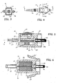
- Passageway 22 extends through main housing 12 . See Fig. 5.
- Splice member 16 is resiliently pressed upward against the flat surface 20 in housing 12 by a spring 18 .
- Spring 18 is shown as a cylindrical spring, but could be any type of a resilient element including a leaf spring.
- a ferrule assembly 24 (which may be of any configuration, although a DC ferrule made by Siecor Corp. of Hickory, N.C. is shown) is inserted into the front part 38 of the housing 12 .
- fiber optic stubs 26 which will mechanically and optically connect with the optical fibers from the cable, are secured within bores of the ferrule assembly 24 , and then the front face 28 of ferrule assembly 24 is polished.
- the fiber optic connector 10 also includes, in this preferred embodiment, two guide pins 30 and a ferrule/guide pin jacket 32 to hold the guide pins in the side grooves 34 of the ferrule assembly 24 .
- the jacket 32 is not necessary and can be replaced by any structure (e.g., an o-ring, a tie, etc.) that would keep the pins 30 aligned in the grooves 34 on either side of the ferrule assembly 24 .
- the ferrule assembly 24 is fixed in the front portion 38 of the main housing 12 by an adhesive, such as epoxy or an equivalent. See, e.g., Figs 5 and 6.
- an adhesive such as epoxy or an equivalent.
- the housing 12 and ferrule assembly 24 be of a unitary construction.
- the ferrule assembly 24 typically with fiber optic stubs 26 already in place, is mounted in the front portion 38 of the main housing 12 .
- a rearward portion of the ferrule assembly 24 is in communication with passageway 22 .
- Splice member 16 is supported by the spring 18 in the passageway 22 , which extends from the front portion 38 behind ferrule assembly 24 through to the rearward portion 40 of main housing 12 .
- spring 18 biases the splice member 16 against the top surface 20 of main housing 12 to hold the fiber optic stubs 26 and the optical fibers in mechanical and optical alignment.
- Figs. 5 and 7 spring 18 biases the splice member 16 against the top surface 20 of main housing 12 to hold the fiber optic stubs 26 and the optical fibers in mechanical and optical alignment.
- back member 14 is shown attached to the rear portion 40 of main housing 12 .
- the spring element 18 is in an opening 42 adjacent to and in communication with the passageway 22 .
- Button 21 is shown in opening 23 in main housing 12 , and in conjunction with Fig. 7, it can be seen that two clip members 44 engage an inner portion of main housing 12 to prevent the button 21 from being lifted or falling out of main housing 12 .
- button 21 has two downward projecting legs 46 to engage and depress the splice member 16 , thereby allowing optical fibers to be inserted between the upper surface 20 and the grooves 48 (see Fig. 6) in the splice member 16 .
- the button 21 when depressed moves the splice member 16 only 100 ⁇ m, a sufficient distance to allow the optical fibers to be inserted into the grooves 48 , but not so as to allow them to be inserted anywhere else in connector 10 . This arrangement ensures that the optical fibers will be in mechanical and optical contact with the fiber optic stubs 26 .
- the grooves are shown in splice member 16 .
- the grooves 48 it is possible for the grooves 48 to also be formed in either the flat upper surface 20 in the main housing 12 or in both the upper surface 22 of the main housing 12 and in the splice member 16 in order to provide a channel for the optical fibers.
- the optical fiber stubs 26 would extend rearwardly from the ferrule assembly 24 about half the distance to the back member 14 along the grooves 48 in splice member 16 .
- the back member 14 has an opening 50 that is bifurcated into two openings 52 to receive the optical fibers from the optical cable (not shown).
- the ferrule assembly 24 is a DC ferrule
- the back member 14 has two fiber bores 52 , which correspond to the two grooves 48 in the splice member 16 and bores in ferrule assembly 24 .
- Other ferrule assemblies having a differing number of fiber bores would have a corresponding number of grooves 48 in the splice member 16 , or upper surface 20 of the housing 12, and back member 14 .
- the fiber bores 52 could be located in elements other than the back member 14 .
- the bores 52 could be at the front end of crimp tube 19 or on the back end of splice member 16 and/or upper surface 20 of the main housing 12 .
- the strain relief boot 54 of Figs. 1, 4, and 8-12 are not shown in Figs. 5 and 6 so that the crimp tube can be clearly seen.
- the fiber optic connector 10 presents a configuration that mimics the MT-RJ configuration.
- the fiber optic connector 10 includes two latches 35 on the outside surface 36 of the fiber optic connector 10 to allow it to engage an associated adapter, shown in Figs. 8-12, rather than the standard MT-RJ latch. As discussed more fully below, this allows the user to change the polarity.
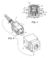
- Figs. 8-12 show fiber optic connector 10 of the present invention with an associated adapter 60.
- Adapter 60 is configured on a first side 62 to engage and hold fiber optic connector 10 in association with latches 35 .
- second side 64 of adapter 60 is configured to receive a MT-RJ type connector.
- the internal configuration of the second side 64 is described in detail in copending application serial number 09/ 118,440 , assigned to same assignee as the present invention, the contents of which are incorporated herein by reference.
- the ferrule assembly 24 and fiber optic connector 10 in Fig. 8 has guide pins
- the MT-RJ connector (not shown) that would be mated in Fig. 8 would not need the guide pins.
- connector 10 would not need to have the pins.
- the connector mounted behind the wall, connector 10 in this application would already have alignment pins installed and the user's connector would not, and could not, have alignment pins.
- the preferred outer configuration adapter 60 is configured such that it will fit a standard RJ-45 keystone footprint faceplate. Therefore, adapter 60 could be inserted into the faceplate by the installer, with second side 64 extending outward towards the desk or end user. The installer would then insert fiber optic connector 10 into first side 62 to provide a fiber connection at the desk or at the wall.
- the second side 64 of the adapter could come in to the wall surface at angles other than 90°, e.g., 45°, 30°, etc.
- the adapter 60 could also be configured to fit other standard openings, provided the openings allowed the adapter to have sufficient internal space to receive the desired connectors.
- Figures 10 and 11 illustrate the fiber optic connector 10 with an adapter 60 that is configured to have a DC ferrule from Siecor Corp. inserted on the second side of the adapter.
- the adapter 60 has a round opening 66 in the center to allow the DC ferrule (see Fig. 2) with two semi-circular slots 68 .
- the guide pins 30 on each side of the connector 10 align in slots 68 , and in conjunction with the opening 66 , align the ferrule assembly 24 in the adapter 60 to mate with a connector inserted from the other side of the adapter.
- fiber optic connector 10 can be inserted in one of two directions. As can be seen from Fig.
- fiber optic connector 10 is symmetrical about the line for the cross section of Fig. 5. Therefore, the installer could, in effect, reverse the polarity of the connection by simply turning fiber optic connector over 180° (with the button 21 facing downward rather that upward) and plugging it back in to the first side 62 . However, the normal installation is with the button 21 being upward, or at least using the button 21 as the reference point. Although not shown, a mark or indicator could be included on one surface of the adapter 60 to indicate the correct orientation for the user. The person installing the connector 10 would then know how to orient connector 10 to assist the user in achieving the correct polarity.
- Figure 12 shows yet another embodiment of adapter 60 as well as a new configuration for the front of fiber optic connector 10 .
- two individual ferrules are secured into the front surface of the main housing 12 rather than a single dual fiber ferrule as shown in the preferred embodiment.
- the remainder of the fiber optic connector 10 will be the same except the grooves in the splice member 16 and/or the upper surface 20 of passageway 22 would be further apart to coincide with the wider-spaced ferrules of this embodiment.
- the front side 64 of adapter 60 in Figure 10 corresponds to the LC connector, sold by Lucent Technologies, Inc.
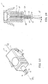
- Figs. 13 and 14 illustrate a fiber optic connector 10 that is the same as that shown in Figs. 1-10 above, but the ferrule assembly has been removed for clarity purposes. Similar parts have been labeled with similar numbers.
- the connector 10 in Figs. 13 and 14 uses, rather than the single crimp tube 19 from the previous embodiments, two crimp tubes 70 .
- the crimp tubes are preferably cylindrical in shape, although square, oval, or other shapes are possible.
- Crimp tube 70 has a first end 72 that is inserted into opening 50 of connector 10 .
- connector 10 is designed to hold two optical fibers and therefore opening 50 has a portion that is bifurcated into two openings 52 to receive the optical fibers.
- Each of the crimp tubes 70 is aligned with one of the openings 52 . While openings 52 are shown in the back member 14 , they may also be in splice member 16 . (It should be understood that the crimp tubes 70 can be used with any connector that uses optical fiber stubs and not only the connectors illustrated herein.)
- the crimp tubes 70 may also have a flared-out portion 74 at the second end 76. As can be seen in Fig. 14, the flared out portion causes the second ends 76 of the crimp tubes 70 to be pushed away from one another and off axis 78 through the center of connector 10 .
- Fig. 14 the flared out portion causes the second ends 76 of the crimp tubes 70 to be pushed away from one another and off axis 78 through the center of connector 10 .
- FIG. 15 illustrates another embodiment of crimp tubes 70 that have a flared out portion 80 that is smaller than flared-out portion 74 .
- the smaller portion 80 causes the angle the tubes 70 are offset to be reduced from that of the first embodiment.
- the crimp tube 70 preferably makes an angle with the axis 78 of between 0.5 and 3 degrees. Therefore, the preferable included angle of one crimp tube relative to the other is between 1 and 6 degrees. This range of angles provides the least amount of skiving of the fiber and achieves the greatest likelihood of insertion into the connector.
- the flared out portions 74,80 also provide the operator with a larger area to assist with insertion of the optical fibers.
- crimp tubes 70 may have their second ends 76 cut on an angle to provide an angled portion 82 .
- the angled portion 82 provides a shelf or wider opening to allow the operator to insert the optical fibers.
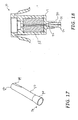
- the crimp tubes 70 may also have a flat portion 84 on an outside surface of first end 72 . See Fig. 17.
- the flat portions 84 are preferably aligned so they engage one another. See Fig. 18, showing a cross-section of the connector 10 with two crimp tubes 70 shown in Fig. 17. This arrangement allows the crimp tubes 70 to fit in a smaller area.
- the angle and the length of the flat portion 84 can be used to control the included angle of the crimp tubes 70 .
- the installer can insert one fiber at a time, rather than having to insert both fibers simultaneously with the oval crimp tube 19 .
- the oval crimp tube 19 it was preferable to insert both fibers to ensure that the correct fiber went into the correct bore.
- the crimp tubes 70 can prevent this from occurring.
Landscapes
- Physics & Mathematics (AREA)
- General Physics & Mathematics (AREA)
- Optics & Photonics (AREA)
- Mechanical Coupling Of Light Guides (AREA)
- Processing Of Terminals (AREA)
Applications Claiming Priority (2)
| Application Number | Priority Date | Filing Date | Title |
|---|---|---|---|
| US483250 | 2000-01-14 | ||
| US09/483,250 US6379052B1 (en) | 1999-05-12 | 2000-01-14 | Removably mounted fiber optic connector and associated adapter |
Publications (2)
| Publication Number | Publication Date |
|---|---|
| EP1116974A2 true EP1116974A2 (de) | 2001-07-18 |
| EP1116974A3 EP1116974A3 (de) | 2004-05-12 |
Family
ID=23919313
Family Applications (1)
| Application Number | Title | Priority Date | Filing Date |
|---|---|---|---|
| EP01100691A Withdrawn EP1116974A3 (de) | 2000-01-14 | 2001-01-11 | Lösbarer faseroptischer Stecker und zugehöriger Adapter |
Country Status (6)
| Country | Link |
|---|---|
| US (1) | US6379052B1 (de) |
| EP (1) | EP1116974A3 (de) |
| JP (1) | JP2001215361A (de) |
| AR (1) | AR029218A1 (de) |
| BR (1) | BR0100267A (de) |
| CA (1) | CA2327007A1 (de) |
Cited By (6)
| Publication number | Priority date | Publication date | Assignee | Title |
|---|---|---|---|---|
| WO2004026530A1 (en) * | 2002-09-19 | 2004-04-01 | 3M Innovative Properties Company | Optical fiber plug |
| WO2004027481A1 (en) * | 2002-09-19 | 2004-04-01 | 3M Innovative Properties Company | Optical fiber plug including fiber stubs and splice channels |
| US6973252B2 (en) | 2002-09-19 | 2005-12-06 | 3M Innovative Properties Company | Article for cleaving and polishing optical fiber ends |
| US9494744B2 (en) | 2014-11-10 | 2016-11-15 | Corning Optical Communications LLC | Fiber optic connector having a main connector body and a plurality of removable sub-connectors |
| CN111263907A (zh) * | 2017-11-02 | 2020-06-09 | 株式会社藤仓 | 光连接器、把持部件、以及光连接器的制造方法 |
| EP2685299B1 (de) * | 2011-03-09 | 2023-05-10 | The Furukawa Electric Co., Ltd. | Optischer stecker, verfahren zum ausrichten einer mehrkernfaser- und bündelstruktur sowie element zum umwandeln einer faseranordnung |
Families Citing this family (72)
| Publication number | Priority date | Publication date | Assignee | Title |
|---|---|---|---|---|
| US7056157B2 (en) * | 2000-05-26 | 2006-06-06 | Hubbell Incorporated | Adapter for data transmission systems |
| AUPS120702A0 (en) * | 2002-03-18 | 2002-04-18 | Kingfisher International Pty. Ltd. | An optical fibre connector system |
| US20040062488A1 (en) * | 2002-09-26 | 2004-04-01 | Charles Wood | Fiber optic adapter sleeve |
| DE10342908A1 (de) * | 2003-09-17 | 2005-04-28 | Krone Gmbh | Gehäuse für Glasfaser- Steckverbinder und Verfahren zum Verlegen von Glasfaserkabeln |
| US7192194B2 (en) * | 2005-01-13 | 2007-03-20 | Frank Giotto | Universal adapter for fiber optic connectors |
| TWM278133U (en) * | 2005-04-14 | 2005-10-11 | John Peng | Shielded waterproof connector |
| US11294136B2 (en) | 2008-08-29 | 2022-04-05 | Corning Optical Communications LLC | High density and bandwidth fiber optic apparatuses and related equipment and methods |
| US8452148B2 (en) | 2008-08-29 | 2013-05-28 | Corning Cable Systems Llc | Independently translatable modules and fiber optic equipment trays in fiber optic equipment |
| ATE534049T1 (de) | 2009-02-24 | 2011-12-15 | Ccs Technology Inc | Haltevorrichtung für ein kabel oder eine anordnung zur verwendung mit einem kabel |
| US8699838B2 (en) | 2009-05-14 | 2014-04-15 | Ccs Technology, Inc. | Fiber optic furcation module |
| US9075216B2 (en) | 2009-05-21 | 2015-07-07 | Corning Cable Systems Llc | Fiber optic housings configured to accommodate fiber optic modules/cassettes and fiber optic panels, and related components and methods |
| US8538226B2 (en) | 2009-05-21 | 2013-09-17 | Corning Cable Systems Llc | Fiber optic equipment guides and rails configured with stopping position(s), and related equipment and methods |
| US8712206B2 (en) | 2009-06-19 | 2014-04-29 | Corning Cable Systems Llc | High-density fiber optic modules and module housings and related equipment |
| WO2010148336A1 (en) | 2009-06-19 | 2010-12-23 | Corning Cable Systems Llc | High density and bandwidth fiber optic apparatuses and related equipment and methods |
| US8625950B2 (en) | 2009-12-18 | 2014-01-07 | Corning Cable Systems Llc | Rotary locking apparatus for fiber optic equipment trays and related methods |
| US8593828B2 (en) | 2010-02-04 | 2013-11-26 | Corning Cable Systems Llc | Communications equipment housings, assemblies, and related alignment features and methods |
| US8913866B2 (en) | 2010-03-26 | 2014-12-16 | Corning Cable Systems Llc | Movable adapter panel |
| AU2011265751B2 (en) | 2010-04-16 | 2015-09-10 | Corning Optical Communications LLC | Sealing and strain relief device for data cables |
| EP2381284B1 (de) | 2010-04-23 | 2014-12-31 | CCS Technology Inc. | Glasfaserverteilungsvorrichtung für Unterboden |
| US8705926B2 (en) | 2010-04-30 | 2014-04-22 | Corning Optical Communications LLC | Fiber optic housings having a removable top, and related components and methods |
| US9519118B2 (en) | 2010-04-30 | 2016-12-13 | Corning Optical Communications LLC | Removable fiber management sections for fiber optic housings, and related components and methods |
| US8879881B2 (en) | 2010-04-30 | 2014-11-04 | Corning Cable Systems Llc | Rotatable routing guide and assembly |
| US9632270B2 (en) | 2010-04-30 | 2017-04-25 | Corning Optical Communications LLC | Fiber optic housings configured for tool-less assembly, and related components and methods |
| US9720195B2 (en) | 2010-04-30 | 2017-08-01 | Corning Optical Communications LLC | Apparatuses and related components and methods for attachment and release of fiber optic housings to and from an equipment rack |
| US9075217B2 (en) | 2010-04-30 | 2015-07-07 | Corning Cable Systems Llc | Apparatuses and related components and methods for expanding capacity of fiber optic housings |
| US8660397B2 (en) | 2010-04-30 | 2014-02-25 | Corning Cable Systems Llc | Multi-layer module |
| JP5471801B2 (ja) * | 2010-05-13 | 2014-04-16 | 住友電気工業株式会社 | 光データリンク |
| US8718436B2 (en) | 2010-08-30 | 2014-05-06 | Corning Cable Systems Llc | Methods, apparatuses for providing secure fiber optic connections |
| US9279951B2 (en) | 2010-10-27 | 2016-03-08 | Corning Cable Systems Llc | Fiber optic module for limited space applications having a partially sealed module sub-assembly |
| US8662760B2 (en) | 2010-10-29 | 2014-03-04 | Corning Cable Systems Llc | Fiber optic connector employing optical fiber guide member |
| US9116324B2 (en) | 2010-10-29 | 2015-08-25 | Corning Cable Systems Llc | Stacked fiber optic modules and fiber optic equipment configured to support stacked fiber optic modules |
| CA2819235C (en) | 2010-11-30 | 2018-01-16 | Corning Cable Systems Llc | Fiber device holder and strain relief device |
| WO2012106510A2 (en) | 2011-02-02 | 2012-08-09 | Corning Cable Systems Llc | Dense fiber optic connector assemblies and related connectors and cables suitable for establishing optical connections for optical backplanes in equipment racks |
| US9008485B2 (en) | 2011-05-09 | 2015-04-14 | Corning Cable Systems Llc | Attachment mechanisms employed to attach a rear housing section to a fiber optic housing, and related assemblies and methods |
| WO2013003303A1 (en) | 2011-06-30 | 2013-01-03 | Corning Cable Systems Llc | Fiber optic equipment assemblies employing non-u-width-sized housings and related methods |
| CN102928931B (zh) * | 2011-08-11 | 2015-02-04 | 鸿富锦精密工业(深圳)有限公司 | 光纤连接器及其安装工具 |
| US8953924B2 (en) | 2011-09-02 | 2015-02-10 | Corning Cable Systems Llc | Removable strain relief brackets for securing fiber optic cables and/or optical fibers to fiber optic equipment, and related assemblies and methods |
| JP5390582B2 (ja) * | 2011-11-25 | 2014-01-15 | 三和電気工業株式会社 | 光コンセント |
| US9038832B2 (en) | 2011-11-30 | 2015-05-26 | Corning Cable Systems Llc | Adapter panel support assembly |
| US9250409B2 (en) | 2012-07-02 | 2016-02-02 | Corning Cable Systems Llc | Fiber-optic-module trays and drawers for fiber-optic equipment |
| US9042702B2 (en) | 2012-09-18 | 2015-05-26 | Corning Cable Systems Llc | Platforms and systems for fiber optic cable attachment |
| ES2551077T3 (es) | 2012-10-26 | 2015-11-16 | Ccs Technology, Inc. | Unidad de gestión de fibra óptica y dispositivo de distribución de fibra óptica |
| US8985862B2 (en) | 2013-02-28 | 2015-03-24 | Corning Cable Systems Llc | High-density multi-fiber adapter housings |
| CN111239918A (zh) * | 2014-06-09 | 2020-06-05 | 扇港元器件有限公司 | 减小轮廓的连接组件 |
| US9618702B2 (en) | 2014-06-09 | 2017-04-11 | Senko Advanced Components, Inc. | Reduced-profile data transmission element connectors, adapters, and connection assemblies thereof |
| US9810861B2 (en) * | 2014-12-19 | 2017-11-07 | 3M Innovative Properties Company | Ruggedized optical fiber connection structures and assemblies |
| US9726830B1 (en) | 2016-06-28 | 2017-08-08 | Senko Advanced Components, Inc. | Connector and adapter system for two-fiber mechanical transfer type ferrule |
| US10444444B2 (en) | 2017-01-30 | 2019-10-15 | Senko Advanced Components, Inc. | Remote release tab connector assembly |
| EP3574356A4 (de) * | 2017-01-30 | 2020-08-19 | Senko Advanced Components Inc. | Optische verbinder mit reversibler polarität |
| US10281668B2 (en) | 2017-07-14 | 2019-05-07 | Senko Advanced Components, Inc. | Ultra-small form factor optical connectors |
| US11822133B2 (en) | 2017-07-14 | 2023-11-21 | Senko Advanced Components, Inc. | Ultra-small form factor optical connector and adapter |
| US12001064B2 (en) | 2017-07-14 | 2024-06-04 | Senko Advanced Components, Inc. | Small form factor fiber optic connector with multi-purpose boot |
| US10718911B2 (en) | 2017-08-24 | 2020-07-21 | Senko Advanced Components, Inc. | Ultra-small form factor optical connectors using a push-pull boot receptacle release |
| US11002923B2 (en) | 2017-11-21 | 2021-05-11 | Senko Advanced Components, Inc. | Fiber optic connector with cable boot release having a two-piece clip assembly |
| CN115201974B (zh) * | 2017-12-19 | 2024-04-30 | 美国康涅克有限公司 | 具有推拉极性机构和载体的微型双工连接器 |
| US11112566B2 (en) | 2018-03-19 | 2021-09-07 | Senko Advanced Components, Inc. | Removal tool for removing a plural of micro optical connectors from an adapter interface |
| EP3776038B1 (de) | 2018-03-28 | 2024-07-03 | Senko Advanced Components Inc. | Faseroptischer steckverbinder mit kleinem formfaktor und multifunktionalem knickschutz |
| CN112088327A (zh) | 2018-07-15 | 2020-12-15 | 扇港元器件股份有限公司 | 超小型光学连接器和适配器 |
| US11073664B2 (en) * | 2018-08-13 | 2021-07-27 | Senko Advanced Components, Inc. | Cable boot assembly for releasing fiber optic connector from a receptacle |
| CN112955797B (zh) | 2018-09-12 | 2022-11-11 | 扇港元器件股份有限公司 | 具有用于利用缆线护套将连接器从插座释放的夹式推/拉舌片的lc型连接器 |
| US10921531B2 (en) | 2018-09-12 | 2021-02-16 | Senko Advanced Components, Inc. | LC type connector with push/pull assembly for releasing connector from a receptacle using a cable boot |
| US10921530B2 (en) | 2018-09-12 | 2021-02-16 | Senko Advanced Components, Inc. | LC type connector with push/pull assembly for releasing connector from a receptacle using a cable boot |
| US11806831B2 (en) | 2018-11-21 | 2023-11-07 | Senko Advanced Components, Inc. | Fixture and method for polishing fiber optic connector ferrules |
| US11175464B2 (en) | 2018-11-25 | 2021-11-16 | Senko Advanced Components, Inc. | Open ended spring body for use in an optical fiber connector |
| US12038613B2 (en) | 2019-03-28 | 2024-07-16 | Senko Advanced Components, Inc. | Behind-the-wall optical connector and assembly of the same |
| US11579379B2 (en) | 2019-03-28 | 2023-02-14 | Senko Advanced Components, Inc. | Fiber optic adapter assembly |
| US11340406B2 (en) | 2019-04-19 | 2022-05-24 | Senko Advanced Components, Inc. | Small form factor fiber optic connector with resilient latching mechanism for securing within a hook-less receptacle |
| CN114026480B (zh) | 2019-06-13 | 2023-05-26 | 扇港元器件有限公司 | 用于从插座端口释放光纤连接器的杆驱动闩锁臂和使用方法 |
| CN114600018B (zh) | 2019-07-23 | 2024-04-09 | 扇港元器件有限公司 | 用于接收与插芯组件相对的光纤连接器的超小型插座 |
| US10782500B1 (en) | 2019-10-25 | 2020-09-22 | Afl Telecommunications Llc | Fiber optic furcation units, kits, and methods |
| GB2589365B (en) * | 2019-11-28 | 2023-11-15 | Ridgemount Tech Limited | Fibre optic connector |
| JP7526637B2 (ja) * | 2020-10-20 | 2024-08-01 | 株式会社フジクラ | 光コネクタおよび光コネクタの製造方法 |
Family Cites Families (7)
| Publication number | Priority date | Publication date | Assignee | Title |
|---|---|---|---|---|
| US4291943A (en) * | 1977-08-05 | 1981-09-29 | Minnesota Mining And Manufacturing Company | Connector for optical fiber cables |
| US4233724A (en) * | 1979-04-20 | 1980-11-18 | Amp Incorporated | Method of accurately positioning fiber cables within ferrules |
| EP0527226A1 (de) * | 1991-03-01 | 1993-02-17 | The Whitaker Corporation | Optische wellenleiterverbindungsvorrichtung |
| JPH09318841A (ja) * | 1996-05-28 | 1997-12-12 | Kel Corp | 光ファイバ用コネクタ |
| US5862289A (en) * | 1997-02-18 | 1999-01-19 | Amphenol Corporation | Adhesiveless fiber optic connector, and an apparatus and method for terminating a fiber optic cable to an adhesiveless fiber optic connector |
| US6173097B1 (en) * | 1998-07-01 | 2001-01-09 | Siecor Operations, Llc | Field installable multifiber connector |
| US6623172B1 (en) * | 1999-05-12 | 2003-09-23 | Corning Cable Systems Llc | Removably mounted fiber optic connector and associated adapter |
-
2000
- 2000-01-14 US US09/483,250 patent/US6379052B1/en not_active Expired - Lifetime
- 2000-11-29 CA CA002327007A patent/CA2327007A1/en not_active Abandoned
-
2001
- 2001-01-02 AR ARP010100007A patent/AR029218A1/es unknown
- 2001-01-10 BR BR0100267-8A patent/BR0100267A/pt not_active Application Discontinuation
- 2001-01-11 EP EP01100691A patent/EP1116974A3/de not_active Withdrawn
- 2001-01-12 JP JP2001005061A patent/JP2001215361A/ja active Pending
Cited By (9)
| Publication number | Priority date | Publication date | Assignee | Title |
|---|---|---|---|---|
| WO2004026530A1 (en) * | 2002-09-19 | 2004-04-01 | 3M Innovative Properties Company | Optical fiber plug |
| WO2004027481A1 (en) * | 2002-09-19 | 2004-04-01 | 3M Innovative Properties Company | Optical fiber plug including fiber stubs and splice channels |
| US6848838B2 (en) * | 2002-09-19 | 2005-02-01 | 3M Innovative Properties Company | Optical fiber plug |
| US6870996B2 (en) | 2002-09-19 | 2005-03-22 | 3M Innovative Properties Company | Optical fiber plug including fiber positioning holder |
| US6973252B2 (en) | 2002-09-19 | 2005-12-06 | 3M Innovative Properties Company | Article for cleaving and polishing optical fiber ends |
| CN100432725C (zh) * | 2002-09-19 | 2008-11-12 | 3M创新有限公司 | 包括光纤短线和连接槽的光纤插头 |
| EP2685299B1 (de) * | 2011-03-09 | 2023-05-10 | The Furukawa Electric Co., Ltd. | Optischer stecker, verfahren zum ausrichten einer mehrkernfaser- und bündelstruktur sowie element zum umwandeln einer faseranordnung |
| US9494744B2 (en) | 2014-11-10 | 2016-11-15 | Corning Optical Communications LLC | Fiber optic connector having a main connector body and a plurality of removable sub-connectors |
| CN111263907A (zh) * | 2017-11-02 | 2020-06-09 | 株式会社藤仓 | 光连接器、把持部件、以及光连接器的制造方法 |
Also Published As
| Publication number | Publication date |
|---|---|
| AR029218A1 (es) | 2003-06-18 |
| BR0100267A (pt) | 2001-08-21 |
| CA2327007A1 (en) | 2001-07-14 |
| EP1116974A3 (de) | 2004-05-12 |
| JP2001215361A (ja) | 2001-08-10 |
| US6379052B1 (en) | 2002-04-30 |
Similar Documents
| Publication | Publication Date | Title |
|---|---|---|
| US6379052B1 (en) | Removably mounted fiber optic connector and associated adapter | |
| US6623172B1 (en) | Removably mounted fiber optic connector and associated adapter | |
| US12013578B2 (en) | Multifiber fiber optic connectors, cable assemblies and methods of making the same | |
| US10215930B2 (en) | Fiber optic connector with field installable outer connector housing | |
| CN100388028C (zh) | 连接器组件夹子 | |
| CN102508340B (zh) | 多纤光纤插座和插头组件 | |
| AU708527B2 (en) | Jack receptacle for an optical connector | |
| US7699533B2 (en) | Back-to-back receptacle | |
| EP1065542A1 (de) | Polaritätsumschaltung für optische Faserverbindung | |
| CA2441872A1 (en) | Keyed fibre optic connector | |
| US11640032B1 (en) | Splice-on fiber optic connector holder |
Legal Events
| Date | Code | Title | Description |
|---|---|---|---|
| PUAI | Public reference made under article 153(3) epc to a published international application that has entered the european phase |
Free format text: ORIGINAL CODE: 0009012 |
|
| AK | Designated contracting states |
Kind code of ref document: A2 Designated state(s): AT BE CH CY DE DK ES FI FR GB GR IE IT LI LU MC NL PT SE TR |
|
| AX | Request for extension of the european patent |
Free format text: AL;LT;LV;MK;RO;SI |
|
| PUAL | Search report despatched |
Free format text: ORIGINAL CODE: 0009013 |
|
| AK | Designated contracting states |
Kind code of ref document: A3 Designated state(s): AT BE CH CY DE DK ES FI FR GB GR IE IT LI LU MC NL PT SE TR |
|
| AX | Request for extension of the european patent |
Extension state: AL LT LV MK RO SI |
|
| 17P | Request for examination filed |
Effective date: 20041009 |
|
| 17Q | First examination report despatched |
Effective date: 20041110 |
|
| AKX | Designation fees paid |
Designated state(s): DE FR GB IT |
|
| GRAP | Despatch of communication of intention to grant a patent |
Free format text: ORIGINAL CODE: EPIDOSNIGR1 |
|
| RTI1 | Title (correction) |
Free format text: REMOVABLY MOUNTED FIBRE OPTIC CONNECTOR |
|
| STAA | Information on the status of an ep patent application or granted ep patent |
Free format text: STATUS: THE APPLICATION IS DEEMED TO BE WITHDRAWN |
|
| 18D | Application deemed to be withdrawn |
Effective date: 20060705 |