EP1117013A2 - Appareil de rechargement en toner - Google Patents
Appareil de rechargement en toner Download PDFInfo
- Publication number
- EP1117013A2 EP1117013A2 EP01100693A EP01100693A EP1117013A2 EP 1117013 A2 EP1117013 A2 EP 1117013A2 EP 01100693 A EP01100693 A EP 01100693A EP 01100693 A EP01100693 A EP 01100693A EP 1117013 A2 EP1117013 A2 EP 1117013A2
- Authority
- EP
- European Patent Office
- Prior art keywords
- bottle
- toner
- powder
- side wall
- receiving member
- Prior art date
- Legal status (The legal status is an assumption and is not a legal conclusion. Google has not performed a legal analysis and makes no representation as to the accuracy of the status listed.)
- Withdrawn
Links
- 239000000843 powder Substances 0.000 claims abstract description 37
- 230000015572 biosynthetic process Effects 0.000 claims 1
- 210000000078 claw Anatomy 0.000 description 4
- 238000003756 stirring Methods 0.000 description 2
- 239000013589 supplement Substances 0.000 description 2
- 230000006835 compression Effects 0.000 description 1
- 238000007906 compression Methods 0.000 description 1
- 230000008878 coupling Effects 0.000 description 1
- 238000010168 coupling process Methods 0.000 description 1
- 238000005859 coupling reaction Methods 0.000 description 1
- 238000002347 injection Methods 0.000 description 1
- 239000007924 injection Substances 0.000 description 1
- 238000009434 installation Methods 0.000 description 1
- 239000000463 material Substances 0.000 description 1
- 230000004048 modification Effects 0.000 description 1
- 238000012986 modification Methods 0.000 description 1
- 239000002991 molded plastic Substances 0.000 description 1
- 230000001502 supplementing effect Effects 0.000 description 1
Images


Classifications
-
- G—PHYSICS
- G03—PHOTOGRAPHY; CINEMATOGRAPHY; ANALOGOUS TECHNIQUES USING WAVES OTHER THAN OPTICAL WAVES; ELECTROGRAPHY; HOLOGRAPHY
- G03G—ELECTROGRAPHY; ELECTROPHOTOGRAPHY; MAGNETOGRAPHY
- G03G15/00—Apparatus for electrographic processes using a charge pattern
- G03G15/06—Apparatus for electrographic processes using a charge pattern for developing
- G03G15/08—Apparatus for electrographic processes using a charge pattern for developing using a solid developer, e.g. powder developer
- G03G15/0822—Arrangements for preparing, mixing, supplying or dispensing developer
- G03G15/0865—Arrangements for supplying new developer
- G03G15/0867—Arrangements for supplying new developer cylindrical developer cartridges, e.g. toner bottles for the developer replenishing opening
- G03G15/087—Developer cartridges having a longitudinal rotational axis, around which at least one part is rotated when mounting or using the cartridge
-
- G—PHYSICS
- G03—PHOTOGRAPHY; CINEMATOGRAPHY; ANALOGOUS TECHNIQUES USING WAVES OTHER THAN OPTICAL WAVES; ELECTROGRAPHY; HOLOGRAPHY
- G03G—ELECTROGRAPHY; ELECTROPHOTOGRAPHY; MAGNETOGRAPHY
- G03G2215/00—Apparatus for electrophotographic processes
- G03G2215/06—Developing structures, details
- G03G2215/066—Toner cartridge or other attachable and detachable container for supplying developer material to replace the used material
- G03G2215/0663—Toner cartridge or other attachable and detachable container for supplying developer material to replace the used material having a longitudinal rotational axis, around which at least one part is rotated when mounting or using the cartridge
- G03G2215/0678—Bottle shaped container having a bottle neck for toner discharge
Definitions
- the present invention relates to apparatus for adding toner to the toner hopper of an electrostatic reproduction machine.
- a toner powder supply system which includes a replaceable toner powder bottle located in an accessible position in the machine.
- a typical toner powder bottle has a base, a top and intermediate side walls, and a powder discharge opening formed in the base.
- Bayonet connecting means on the bottle cooperate with corresponding bayonet connecting means of a bottle receiving member to which the toner bottle is connected in use.
- the bottle is provided with a valve having an open position allowing flow of toner powder through the powder discharge opening and a closed position preventing flow of toner powder through the powder discharge opening.
- Cooperating valve actuating means formed on the bottle and the receiving member actuate the valve into the open position when the bottle is connected to the receiving member and into the closed position when the bottle is disconnected from the receiving member.
- the toner consumption is low, so that an amount of the toner to be supplemented into the toner hopper is relatively small, requiring a toner bottle with a small capacity. Therefore, the toner use can be easily supplemented into the toner hopper by grasping the toner bottle at the top.
- U.S. Pat. No. 4,060,105 to Feldeisen et al. discloses a toner loading apparatus including a toner bottle and receiver which co-act so as to eliminate or minimize the danger of generating toner clouds or spilling toner during the loading operation.
- the bottle has a body and a cap rotatably mounted on one end of the body.
- the body has a plurality of locating and locking lugs, which co-act with corresponding channels in the receiver so that the bottle can be inserted into the receiver in only one position.
- the bottle is simultaneously locked onto the hopper by the lugs being moved out of alignment with their corresponding channels. After being locked onto the hopper a bellows portion of the body is compressed to expel toner into the hopper.
- U.S. Pat. No. 4,615,364 to Kawata discloses a developer-supplying device including a developer hopper, a developer receptacle, and a spring-operated developer inlet cover.
- a bayonet type coupling member couples the receptacle to the hopper by rotation after the receptacle is installed on the hopper.
- a developer receptacle wall which forms the bottom of the receptacle when the latter is upended at the time developer is being supplied is formed on a slope to facilitate flow of the powdered developer from the receptacle, through the opening into the hopper.
- U.S. Pat. No. 5,089,854 to Kaieda discloses a toner supplementing container including a toner bottle having an opening, a shutter member movable between a closed position, in which the opening of the toner bottle is closed by the shutter member, and an open position, in which the opening of the toner bottle is not closed by the shutter member, and a shutter locking member for locking the shutter member into the closed position. Also disclosed is a hopper including a locking mechanism which allows movement of the shutter member of the toner bottle into the open position only when the locking mechanism is in its locked position.
- U.S. Pat. No. 5,345,297 to Katakabe et al. discloses a toner container including a toner container, a rotary shaft extending through the body of the toner container, a stirring vane fixed to one end of the rotary shaft, and a toner valve which is held in pressure contact with a seat for a toner discharge port by a compression spring, which is provided on the upper portion of the rotary shaft. As the rotary shaft is lifted, the toner valve is spaced from the seat for the toner discharge port and toner is discharged. The rotary shaft and attached stirring vane may be rotated to agitate the toner and increase toner fluidity.
- U.S. Pat. No. 5,710,963 to Dirx discloses a toner powder bottle including a bayonet mount for connection to a toner hopper and finger recesses formed in the conical walls adjacent to the top to facilitate axial and rotational manipulation of the bottle, thereby enabling connection of the bottle to the toner hopper.
- a toner powder bottle for supplying toner to an electrostatographic printing machine.
- the toner powder bottle includes a top, a base, a side wall, a powder discharge opening formed in the base, and connection means.
- the connection means cooperates with a corresponding connection means of a bottle receiving member to which the toner bottle is connected when in use. Facets are formed in the side wall of the toner bottle, with the facets providing flat lateral and axial function surfaces to facilitate axial and rotational manipulation of the bottle to enable connection of the bottle to the bottle receiving member.
- a printing machine of the type having a toner supply system.
- the toner supply system includes a toner powder bottle and a receiving member to which the bottle is connected when in use.
- the bottle includes a top, base, a powder discharge opening formed in the base, side walls, and connection means, which cooperates with corresponding connection means on the receiving member. Facets are formed in the side walls of the toner bottle, with the facets providing flat lateral and axial function surfaces to facilitate axial and rotational manipulation of the bottle.
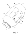
- FIG. 1 is an elevational view of the present invention.
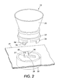
- FIG. 2 is an elevational view of the lower portion of the bottle and the bottle- receiving member of an electrostatographic printing machine.
- FIG. 3 is a top view of the toner bottle.
- FIG. 4 is an elevational view of the toner bottle in position in a printing or copying machine.
- the toner powder bottle 10 of the present invention which is formed of blow molded plastic material, has an open base 14 , a closed top 16 and intermediate side walls 18.
- the side walls 18 are substantially free from protrusions to enable the bottle to be of the maximum possible volume to fit within the space available within an electrostatographic copier or printer.
- the bottle 10 has an upper frusto-conical portion 20 , a lower frusto-conical portion 22 , and an intermediate portion 24 .
- the open base 14 defines a powder discharge opening 25 .
- the base 14 includes fixing lugs 29 to which a powder dispensing cap (not shown in FIGS. 1 and 2 ) is fitted.
- FIG. 2 there is shown the lower frusto-conical portion 22 of the bottle having a powder dispensing cap 32 fixed to the base of the bottle.
- the powder dispensing cap 32 has an open position allowing flow of toner powder through the powder discharge opening 25 and a closed position preventing flow of toner powder through the powder discharge opening 25 .
- the powder dispensing cap is injection molded and is of a type known to the art. Also formed on the powder dispensing cap are three bayonet claws, equally angularly spaced.
- the bottle 10 together with attached powder dispensing cap 32 , are connected in use to a bottle receiving member in the form of a hopper piece 30 , carried on a support plate 31 of the toner hopper 38 (indicated in FIG. 4 ) of a copying or printing machine.
- the hopper piece 30 is in the form of an open cylinder having three bayonet grooves 28 formed in the walls thereof, opening via notches 35 to the upper face of the hopper piece 30 .
- the bayonet claws 26 co-operate with the bayonet grooves 28 formed on the hopper piece 30 .
- Each of the notches 35 has a first side face 36 , which acts upon the actuator arm 34 of the dispensing cap 32 .
- the actuator arm 34 is rotated relative to the valve body causing the valve 32 to open.
- the bayonet connecting means 26 and the dispensing cap actuating means 34, 36 are operable by rotation of the bottle 10 through an angle of 90°.
- the notches 35 also each have a second side face 37 , which acts upon the actuator arm 34 of the dispensing cap 32 when the bottle is rotated counter-clockwise to release the bayonet claws 26 from the bayonet grooves 28 .
- the actuator arm 34 is rotated in the opposite direction relative to the dispensing cap, causing the dispensing cap 32 to close.
- the bottle can therefore be removed from the machine without fear of spillage of any remaining toner powder, which may remain therein.
- facets 40 are formed in the intermediate cylindrical section 24 between the upper frusto-conical portion 20 and the lower frusto-conical portion 22 .
- Each facet 40 has a generally flat configuration, side edges 42 and 44 and top and bottom edges 46 and 48 thereof forming a flat lateral and axial function surface. The function surface facilitates axial and rotational manipulation of the bottle 10 to enable connection of the bottle 10 to the hopper piece 30 .
- FIG. 3 illustrates a generally curved region 49 of the intermediate cylindrical section 24 in which facets are not formed.
- FIG. 4 shows the bottle 10 in position in a printing or copying machine.
- the dashed lines W indicate the position of adjacent walls and other components of the machine. These walls and components restrict access to the top 16 of the bottle.
- the provision of the facets 40 in the intermediate cylindrical section of the bottle enable the operator to insert the bottle 10 into the machine and connect it to the hopper 38 , by grasping the intermediate cylindrical section and rotating the bottle 10 . Manipulation of the bottle is thereby less hindered by the walls of the machine while the bottle is designed to have the maximum possible volume.
- the bottle shown in the accompanying Figures holds approximately 0.8 or 1.0 kg toner powder and is used as a replacement for a conventional bottle, which held 0.8 kg powder.
Landscapes
- Physics & Mathematics (AREA)
- General Physics & Mathematics (AREA)
- Dry Development In Electrophotography (AREA)
Applications Claiming Priority (2)
| Application Number | Priority Date | Filing Date | Title |
|---|---|---|---|
| US09/482,852 US20010008592A1 (en) | 2000-01-14 | 2000-01-14 | Toner loading apparatus |
| US482852 | 2000-01-14 |
Publications (1)
| Publication Number | Publication Date |
|---|---|
| EP1117013A2 true EP1117013A2 (fr) | 2001-07-18 |
Family
ID=23917697
Family Applications (1)
| Application Number | Title | Priority Date | Filing Date |
|---|---|---|---|
| EP01100693A Withdrawn EP1117013A2 (fr) | 2000-01-14 | 2001-01-11 | Appareil de rechargement en toner |
Country Status (3)
| Country | Link |
|---|---|
| US (1) | US20010008592A1 (fr) |
| EP (1) | EP1117013A2 (fr) |
| JP (1) | JP2001228695A (fr) |
Families Citing this family (7)
| Publication number | Priority date | Publication date | Assignee | Title |
|---|---|---|---|---|
| USD482059S1 (en) | 2002-11-12 | 2003-11-11 | Xerox Corporation | Toner loading bottle |
| USD475397S1 (en) | 2002-11-12 | 2003-06-03 | Xerox Corporation | Toner loading bottle |
| US9063463B2 (en) * | 2012-11-30 | 2015-06-23 | Xerox Corporation | Systems and methods for facilitating advanced toner dispensing from rotating toner cartridge components |
| JP7006094B2 (ja) | 2017-09-28 | 2022-01-24 | ブラザー工業株式会社 | 画像形成装置 |
| CN112041758B (zh) * | 2018-08-30 | 2023-11-10 | 惠普发展公司,有限责任合伙企业 | 打印颗粒补充装置 |
| JP2020158911A (ja) * | 2019-03-26 | 2020-10-01 | セイコーエプソン株式会社 | 添加剤収容具 |
| US11269266B2 (en) * | 2019-08-05 | 2022-03-08 | Canon Kabushiki Kaisha | Image forming apparatus and developer replenishment thereof |
-
2000
- 2000-01-14 US US09/482,852 patent/US20010008592A1/en not_active Abandoned
-
2001
- 2001-01-09 JP JP2001001025A patent/JP2001228695A/ja not_active Withdrawn
- 2001-01-11 EP EP01100693A patent/EP1117013A2/fr not_active Withdrawn
Also Published As
| Publication number | Publication date |
|---|---|
| JP2001228695A (ja) | 2001-08-24 |
| US20010008592A1 (en) | 2001-07-19 |
Similar Documents
| Publication | Publication Date | Title |
|---|---|---|
| US5441177A (en) | Toner container and toner replenishing device including a cap member having a shutter | |
| US5710963A (en) | Toner powder bottle | |
| US6363235B1 (en) | Toner bottle/cartridge housing attachment assembly | |
| US6332065B1 (en) | CRU/toner bottle connector assembly | |
| US6256469B1 (en) | Toner supply apparatus in image forming system | |
| RU2644081C1 (ru) | Контейнер порошка и устройство формирования изображения | |
| US4990964A (en) | Toner delivery system having a multi-functional toner container for non-mechanical printer and copier means | |
| US5768662A (en) | Toner supply cartridge for rotary developing device | |
| US5991584A (en) | Toner cartridge assembly | |
| EP1220052A2 (fr) | Récipient de développateur et appareil de formation d'images | |
| US4752807A (en) | Apparatus for adding toner to an electrographic development station | |
| CN115407631B (zh) | 显影剂供应容器 | |
| JPS62158681A (ja) | 粉状物の分配カ−トリツジ | |
| EP1117013A2 (fr) | Appareil de rechargement en toner | |
| JP2010511573A (ja) | 粉体およびペーストのための投与量分配装置 | |
| CN111108446A (zh) | 显影剂供应容器和显影剂供应系统 | |
| US6209995B1 (en) | Ink reservoir, ink reservoir refill container, and ink refill process | |
| US6628910B2 (en) | Toner cartridge for image forming apparatus | |
| JP3684843B2 (ja) | 現像剤補給装置 | |
| JP4681854B2 (ja) | 封止部材、トナー補給容器及び画像形成装置 | |
| CN100401203C (zh) | 显影剂供应装置和显影剂供应容器 | |
| US5472026A (en) | Toner loading system having a swiveling extendible filler snout | |
| US5028961A (en) | Development apparatus having a developer material storage chamber which automatically discharges upon operation of the mixer | |
| JP3012601B2 (ja) | インクカートリッジ攪拌装置 | |
| JP3917761B2 (ja) | トナー補給装置 |
Legal Events
| Date | Code | Title | Description |
|---|---|---|---|
| PUAI | Public reference made under article 153(3) epc to a published international application that has entered the european phase |
Free format text: ORIGINAL CODE: 0009012 |
|
| AK | Designated contracting states |
Kind code of ref document: A2 Designated state(s): AT BE CH CY DE DK ES FI FR GB GR IE IT LI LU MC NL PT SE TR |
|
| AX | Request for extension of the european patent |
Free format text: AL;LT;LV;MK;RO;SI |
|
| STAA | Information on the status of an ep patent application or granted ep patent |
Free format text: STATUS: THE APPLICATION IS DEEMED TO BE WITHDRAWN |
|
| 18D | Application deemed to be withdrawn |
Effective date: 20030801 |