EP1117018B1 - Systeme structure de controle et de commande de l'equipement technique d'une installation - Google Patents
Systeme structure de controle et de commande de l'equipement technique d'une installation Download PDFInfo
- Publication number
- EP1117018B1 EP1117018B1 EP99949483A EP99949483A EP1117018B1 EP 1117018 B1 EP1117018 B1 EP 1117018B1 EP 99949483 A EP99949483 A EP 99949483A EP 99949483 A EP99949483 A EP 99949483A EP 1117018 B1 EP1117018 B1 EP 1117018B1
- Authority
- EP
- European Patent Office
- Prior art keywords
- control
- monitoring
- building
- engineering equipment
- units
- Prior art date
- Legal status (The legal status is an assumption and is not a legal conclusion. Google has not performed a legal analysis and makes no representation as to the accuracy of the status listed.)
- Expired - Lifetime
Links
Images
Classifications
-
- G—PHYSICS
- G05—CONTROLLING; REGULATING
- G05B—CONTROL OR REGULATING SYSTEMS IN GENERAL; FUNCTIONAL ELEMENTS OF SUCH SYSTEMS; MONITORING OR TESTING ARRANGEMENTS FOR SUCH SYSTEMS OR ELEMENTS
- G05B23/00—Testing or monitoring of control systems or parts thereof
- G05B23/02—Electric testing or monitoring
- G05B23/0205—Electric testing or monitoring by means of a monitoring system capable of detecting and responding to faults
- G05B23/0208—Electric testing or monitoring by means of a monitoring system capable of detecting and responding to faults characterized by the configuration of the monitoring system
- G05B23/0213—Modular or universal configuration of the monitoring system, e.g. monitoring system having modules that may be combined to build monitoring program; monitoring system that can be applied to legacy systems; adaptable monitoring system; using different communication protocols
-
- G—PHYSICS
- G05—CONTROLLING; REGULATING
- G05B—CONTROL OR REGULATING SYSTEMS IN GENERAL; FUNCTIONAL ELEMENTS OF SUCH SYSTEMS; MONITORING OR TESTING ARRANGEMENTS FOR SUCH SYSTEMS OR ELEMENTS
- G05B15/00—Systems controlled by a computer
- G05B15/02—Systems controlled by a computer electric
-
- G—PHYSICS
- G05—CONTROLLING; REGULATING
- G05B—CONTROL OR REGULATING SYSTEMS IN GENERAL; FUNCTIONAL ELEMENTS OF SUCH SYSTEMS; MONITORING OR TESTING ARRANGEMENTS FOR SUCH SYSTEMS OR ELEMENTS
- G05B19/00—Program-control systems
- G05B19/02—Program-control systems electric
- G05B19/04—Program control other than numerical control, i.e. in sequence controllers or logic controllers
- G05B19/042—Program control other than numerical control, i.e. in sequence controllers or logic controllers using digital processors
- G05B19/0421—Multiprocessor system
-
- G—PHYSICS
- G05—CONTROLLING; REGULATING
- G05B—CONTROL OR REGULATING SYSTEMS IN GENERAL; FUNCTIONAL ELEMENTS OF SUCH SYSTEMS; MONITORING OR TESTING ARRANGEMENTS FOR SUCH SYSTEMS OR ELEMENTS
- G05B2219/00—Program-control systems
- G05B2219/20—Pc systems
- G05B2219/25—Pc structure of the system
- G05B2219/25011—Domotique, I-O bus, home automation, building automation
-
- G—PHYSICS
- G05—CONTROLLING; REGULATING
- G05B—CONTROL OR REGULATING SYSTEMS IN GENERAL; FUNCTIONAL ELEMENTS OF SUCH SYSTEMS; MONITORING OR TESTING ARRANGEMENTS FOR SUCH SYSTEMS OR ELEMENTS
- G05B2219/00—Program-control systems
- G05B2219/20—Pc systems
- G05B2219/25—Pc structure of the system
- G05B2219/25016—Eiba bus, european installation bus association, ib installation bus
-
- G—PHYSICS
- G05—CONTROLLING; REGULATING
- G05B—CONTROL OR REGULATING SYSTEMS IN GENERAL; FUNCTIONAL ELEMENTS OF SUCH SYSTEMS; MONITORING OR TESTING ARRANGEMENTS FOR SUCH SYSTEMS OR ELEMENTS
- G05B2219/00—Program-control systems
- G05B2219/20—Pc systems
- G05B2219/25—Pc structure of the system
- G05B2219/25022—LAN local area network for controllers
-
- G—PHYSICS
- G05—CONTROLLING; REGULATING
- G05B—CONTROL OR REGULATING SYSTEMS IN GENERAL; FUNCTIONAL ELEMENTS OF SUCH SYSTEMS; MONITORING OR TESTING ARRANGEMENTS FOR SUCH SYSTEMS OR ELEMENTS
- G05B2219/00—Program-control systems
- G05B2219/20—Pc systems
- G05B2219/25—Pc structure of the system
- G05B2219/25035—Star network
-
- G—PHYSICS
- G05—CONTROLLING; REGULATING
- G05B—CONTROL OR REGULATING SYSTEMS IN GENERAL; FUNCTIONAL ELEMENTS OF SUCH SYSTEMS; MONITORING OR TESTING ARRANGEMENTS FOR SUCH SYSTEMS OR ELEMENTS
- G05B2219/00—Program-control systems
- G05B2219/20—Pc systems
- G05B2219/25—Pc structure of the system
- G05B2219/25232—DCS, distributed control system, decentralised control unit
Definitions
- the invention relates to a structured system for monitoring and controlling an engineering equipment in an installation, mainly a building comprising several floors.
- the system includes a central computer module with an input-output-device, as well as a plurality of monitoring and/or measuring and/or control sensors and/or control devices for units or apparatus of the engineering equipment in the building connected via communication hubs to a centralized power supply system and units for independent control of said engineering equipment.
- the central computer module consists of a programmable computer server station having functions, according to a software, that provide for a centralized acquisition of monitoring data through information channels within a single network protocol, as well as for the processing of said monitoring data and for the output of control signals to the control devices for the units or apparatus of the engineering equipment in the building.
- Controllers are placed at the points of location of the communication hubs connected in a hierarchical-star circuit or a bus circuit to a central distribution frame of the centralized power supply system and units for off-line control of the engineering equipment, and further connected in a hierarchical-star circuit or a bus circuit to the input-output device of the central computer module, each of said controllers having a plurality of remote input-output modules connected serially or in above-mentioned star circuit thereto, while each of said remote input-output modules is further connected to a corresponding monitoring and/or measuring and/or control sensor and/or control device for a specific unit or apparatus of the engineering equipment in the building connected thereto.
- Each such monitoring sub-system performs limited local tasks of the automation and manual supervision of an existing engineering system.
- Analysis of existing systems indicates that to a greater or lesser degree such solutions have the following drawbacks in common: shortage of information for the maintenance services; lack of coordination between monitoring elements of various engineering systems; poor overall reliability of technological processes; use of morally outdated hardware; lack of unification of the equipment and cabling; lack of readily available spare equipment; high operational costs; slow reaction to failures of the equipement and restoration of the serviceability thereof; absence of engineering solutions to ensure sutained functioning of the systems; lack of automatic control functionality; limited dispatch capabilities due to the absence of means for remove transmission of information to the maintenance services of the building.
- the above-listed shortcomings can be eliminated by applying the technique of constructing a structured system for monitoring and controlling the engineering equipment of an installation.
- the main principles of such a technique are as follows: use of a common structured cable network within the installation; creation of a hierarchically structured control and information gathering system; concentration of information and distribution thereof according to the needs and levels of authority; integrated automation of information accounting and processing functions; integration with higher-level automatic management, control and information systems in the capacity of an information-supplying agent; use of engineering system equipment with a built-in monitoring and control functionality; unification of equipment and informational support; standardization of design solutions.
- the hierarchical structure of information gathering and management within the monitoring and control system makes it possible to integrate such structured monitoring and control system with other automated supervision and information systems making part of situational centers of various levels.
- Unification of the monitoring equipment makes it possible to reduce maintenance costs and shorten serviceability restoration time.
- the prior art knows a system for monitoring and controlling active engineering equipment built around a central computer module with an input-output device to which a plurality of monitoring and/or measuring and/or control sensors and control devices for the units and apparatus of the active engineering equipment in the building is linked via channels of an information network.
- the module consists of a programmable computer server station having functions, according to the software, that provide for the centralized acquisition of monitoring data through information channels within a single network protocol, as well as for the processing of said data and for the output of control signals to the control devices for the units and apparatus of the engineering equipment in the building (ref US Patent No. 5684374, G05 ⁇ 13/00, published 04.11.97).
- a specific feature of such a system is that all monitoring and control sensors and control devices thereof are linked directly to the input-output controller of the computer server station, which is the sole central controller.
- Such a system is justifiable for offices or buildings with a relatively small floor area, in which said sensors or devices are located in immediate proximity to the controller. In situations where the sensors are located at considerable distances from the controller, long cables have to be laid, which is not always justifiable economically.
- a scheme for monitoring and controlling said equipment leads to an excessive complexity of the scheme proper, makes it difficult to lay and debug, lowers throughput capacity, and results in the lack of support software with which these deficiencies can be eliminated.
- the prior art also knows another structured system for monitoring and controlling the engineering equipment of an installation, mainly a building comprising several floors.
- the system includes a central computer module with an input-output device to which a plurality of monitoring and/or measuring and/or control sensors and control devices for the units and apparatus of the engineering equipment in the building are linked via channels of an information network.
- the module consists of a programmable computer server station having functions, according to the software, that provide for the centralized acquisition of monitoring data through information channels within a single network protocol, as well as for the processing of said data and for the output of control signals to the control devices for the units and apparatus of the active engineering equipment in the building (ref. DE, Application No. 4125839, G05B 1500, published 04.02.93).
- the prior art also knows a system automation of the engineering equipment of a building that includes a supervising unit for supervising all the facilities of the building that is connected to sensors and actuators via a prewired network and local pre-automation devices common to all the facilities (ref. WO-A-95/27929, published 19.10.95).
- network-based monitoring and control systems are required to transmit not only digital (text) data, but also voice and video information.
- corresponding broadband applications have been developed, including multimedia and full-scale digital video conferencing applications.
- multimedia and full-scale digital video conferencing applications For these applications to be used, the transmission speeds and the volume of traffic in the local and global networks need be increased considerably.
- the network cables should naturally be designed so as to preclude signal loss therein.
- the object of the invention is achieved by a structured system for monitoring and controlling as defined in claim 1.
- the engineering result achieved consists in an improvement of the performance characteristics and efficiency of the monitoring and control system, and thus an improvement of the overall reliability of the functioning of the engineering systems in the building.
- This engineering result is achieved through the use of a structured system for monitoring and controlling the engineering equipment in an installation, mainly a building comprising several floors.
- This system includes a central computer module with an input-output device as well as a plurality of monitoring and/or measurement and/or control sensors and/or control devices for the units and apparatus of the engineering equipment in the building.
- the module consists of a programmable computer server station having functions, according to the software, that provide for the centralized acquisition of monitoring data through information channels within a single network protocol, as well as for the processing of said data and for the output of control signals to the control devices for the units and apparatus of the engineering equipment in the building.
- This system further includes controllers connected in a star circuit to the input-output device of the central computer module.
- Each controller has a plurality of remote input-output modules serially connected thereto, while each of said modules is linked to a corresponding monitoring and/or measuring and/or control sensor and/or device for controlling a specific unit or apparatus of the engineering equipment in the building.
- Each such controller has remote input-output modules connected thereto, which are in turn linked to said sensors or control devices related to the units and apparatus of at least one functionally independent section of the engineering equipment in the building.
- the functionally independent section of the engineering equipment in the building includes units and apparatus of the lift equipment, or pump equipment, or heat supply station, or electric power supply system of the building.
- the sensors and control devices that put out information-carrying signals in a format other than that of the common network protocol are connected to the appropriate controller via a data converter designed to convert data of one network protocol into data of another network protocol.
- the system is connected to a plurality of uninterrupted power supplies, which ensures survivability of the system against possible power outages.
- the controllers can be positioned at the points of location of the communications hubs that link the engineering equipment in the building to the common electric power supply system.
- monitoring and measuring sensors can be performed by level, flow, temperature and pressure sensors, respectively, while infrared sensors, photosensors and heat sensors can be used as the control sensors.
- the control devices are servo drives or drives having the function of performing an action in response to the signal from a sensor.
- These devices can be represented by apparatus for controlling the position of window blinds or window leafs, devices for remote opening/closing of doors or on/off switching of lights.
- the above-mentioned features are material, are inter-related with one another, and form a stable combination of material features sufficient to obtain the requisite engineering result.
- connection of the controllers to the input-output device of the central computer module in a hierarchical star circuit makes it possible, even with the use of cable sections of a limited length, to ensure a constancy of signal parameters during the transmission thereof over these sections while preserving the scheme of communication between the central module and the remote input-output modules to which the sensors and control devices are connected. It also becomes possible to place each such controller in the communications hub on a separate floor and use additional cabling to provide a link to the equipment available on said floor.
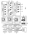
- the structured system for monitoring and controlling the engineering equipment of an installation in the form of a building comprising several floors includes a central computer module 1 with an input-output device 2.
- the module is a programmable computer server station 3 having functions, according to the software, that provide for the centralized acquisition of monitoring data through information channels within a single network protocol, as well as for the processing of said data and for the output of control signals to the control devices of the units and apparatus of the engineering equipment in the building.
- the server station also includes a redundant server 4.
- Used in the capacity of the programmable computer server station can be the station described in DE, No. 4125839, US, No. 5684374, or a station of the AlphaServer family manufactured by DIGITAL corporation (ref the leaflet "AlphaServer Family" published by DIGITAL corporation).
- Citect software package Used as software having the required functionality is the Citect software package (ref "Seize the Power" leaflet published in 1997 by Ci Technologies Pty Limited and devoted to Citect, version 5).
- Citect is a manager program with a differentiation of the levels of authority.
- the Citect software package is intended to provide a visual presentation of the object of automation.
- the program allows the operator to view the status and condition of all automated systems and apparatus in a dynamic mode and to produce control actions.
- the Citect package can also generate reports and output them to a printer to obtain said reports in hard copy at a preset time or at predetermined time intervals.
- the program includes a graphics editor which can be used to create images (video frames) on the computer monitor screen that will reflect the physical processes which take place in the real objects of automation and which the operator must monitor.
- the program allows the operator to observe current values of the parameters being monitored and the condition of damaged and other objects, perform manual control functions, change control coefficients, etc.
- Control of the object of automation can be effected with the use of a computer mouse, a functional keyboard or a standard keyboard, or from a special control board.
- the input-output device 2 of the central computer module has a plurality of controllers 5 connected thereto in a hierarchical-star (bus-star) circuit or in a bus (a bus-group) circuit.
- the function of the controllers is to support the process of data exchange and conversion of data from one protocol to another protocol.
- Each of the controllers has a plurality of remote input-output modules 6 connected thereto in a hierarchical-star circuit, while each of said modules is further connected to a corresponding monitoring and/or measuring and/or control sensor and/or control device for a specific unit or apparatus of the engineering equipment in the building.
- the controllers are placed at the points of location of communications hubs 7, which are connected in a hierarchical-star circuit to a central distribution frame 8 of the centralized power supply system and units 9 for off-line control of the engineering equipment (for details on connecting the equipment in a "hierarchical-star” circuit see the leaflet "AN&T SYSTIMAX®SCS. Recommendations on the Planning of Wiring of Copper and Optical Cables” by Lucent Technologies, 1996, page 3").
- Used as the controller 5 can be the multi-channel controller described in US, No. 5684374 (Ref. No. 16) and known as "IMC S Class Compact", manufactured by Allen-Bradley company (US), or a controller of the AC 31 series manufactured by ABB concern (ref. ABB's leaflet "AC 31 - A New Opening for Automation", 1998, pages 1 through 23).
- ABB leaflet describes remote input-output modules (controllers) that can be used as the remote input-output modules 6 within the scope of the present invention.
- controllers have the hardware and software needed to organize the exchange of data with stand-alone systems having a serial interface.
- the controllers 5 are joined into groups by a plurality of MODBUS buses (ref. earlier cited ABB leaflet, page 5) according to either a functional or a territorial principle.
- the total number of said buses depends on the number of ports available in the device that supports communication with the server.
- the remote input-output modules 6 are connected by means of bus CS 31BUS (ref. earlier cited ABB leaflet, pages 12 and 13) to the corresponding controller 5 either serially or in a hierarchical-star circuit.
- the controllers are placed at the points of location of said communications hubs. This allows the monitoring and/or measuring and/or control sensors and control devices for the engineering equipment available on said floor to be connected on a floor-by-floor basis.
- Used as monitoring sensors 10 and/or measuring sensors 11 are, respectively, level, flow, temperature, pressure, etc. sensors with the functionality, according to the design thereof, of passively registering and reflecting, in one form or another, the current value of a specific parameter.
- control sensors 12 Used as control sensors 12 are infrared sensors, photosensors and heat sensors belonging to the category of apparatus a change in the state whereof can be utilized as a control signal for switching some system or device on or off.
- said systems or devices are understood to include those from the plurality of known systems as, for example, a fire alarm system and an air conditioning or ventilation system responding to the signal of a dust sensor.
- Control devices 13 are understood to include servo drives or other drives having the function of performing an action in response to a signal from a sensor.
- Said drives and servo drives can be represented by apparatus for controlling the position of blinds, devices for remote opening/closing of doors or on/off switching of lights.
- each local engineering system which is a functionally independent section of the engineering equipment in the building and which includes units and apparatus of the lift equipment, or pump equipment, or heat supply station, or electric power supply system or ventilation equipment thereof, is a complete module capable of functioning both independently and as part of the claimed monitoring and control system.
- the modular structure ensures maximum flexibility and survivability of the system as a whole.
- Each module includes primary sensors and actuating devices, as well as devices 14 for matching the outputs of the primary sensors with the inputs of the controllers 5 or the remote input-output modules 6.
- each of the controllers within the claimed monitoring and control system can be remote input-output devices with which the primary sensors or control devices associated with the units and apparatus in at least one functionally independent section of the engineering equipment in the building are linked.
- At least one additional computer station 15 is connected to a specific input of a specific controller.
- the station 15 has its input-output module linked via a dedicated channel with the corresponding controller, and is further connected through local area network 16 to the central computer module.
- This communication arrangement allows the operator of the central computer module to have part of the information transmitted to the station 15, and thus to enable the operator thereof to perform off-line monitoring of the functioning of the units and apparatus of the separate engineering equipment module.
- the additional computer stations are arranged in a hierarchical-start circuit and can communicate with one another over the information channel(s) through standard local area network hubs in the dedicated channels of the controllers 5.
- Each functionally independent section or module of the engineering equipment in the building can be equipped with said stations 15.
- the present system is designed so as to permit incorporation thereof into the network of already existing monitoring systems, such as those employing the EIB protocol standard (ref. the leaflet "ABB i-bus® EIB Intelligent Installation System. A Step into the Future" published by ABB concern, 1996, pages 4 to 7).
- a converter 17 is interposed in the data lines of the EIB bus that provide a link to the corresponding controller 5.
- the function of said controller is to convert the data of one protocol into data of another protocol, for example the MODBUS.
- the system be connected to a plurality of uninterrupted power supplies (not shown).
- the central computer module can then be provided with the means for connecting it to an external global network to permit communication with other external monitoring and control systems.
- the Citect software package provides a remote monitoring capability based on the use of known hardware (ref. the leaflet "American Ref-Fuel” published by Ci Technologies Pty Limited, US, January 1998, page 8).
- the present invention makes it possible, by altering the scheme of the monitoring and control system, to ensure full monitoring and control coverage of the entire equipment of the engineering systems and complexes regardless of the location thereof with respect to the central computer module while retaining the network throughput capacity and signal quality.
- the present system makes it possible to not only perform centralized gathering of information and exercise control from a common center, but also to have part of its functions transferred to the local stations that service functionally independent engineering complexes and systems, while retaining the capability of monitoring the functioning of said stations.
- the present invention is industrially applicable, because it is based not on the use of any new means that permit implementation of monitoring and control functions, but rather on a new combination of the links between thereof This makes it possible to ensure full monitoring and control coverage of the entire equipment of the engineering systems and complexes regardless of the location thereof with respect to the central computer module, while retaining the network throughput capacity and signal quality, as well as to build networks of any configurations depending on the application software.
Landscapes
- Engineering & Computer Science (AREA)
- General Physics & Mathematics (AREA)
- Automation & Control Theory (AREA)
- Physics & Mathematics (AREA)
- General Engineering & Computer Science (AREA)
- Selective Calling Equipment (AREA)
- Nitrogen And Oxygen Or Sulfur-Condensed Heterocyclic Ring Systems (AREA)
- Train Traffic Observation, Control, And Security (AREA)
- Input From Keyboards Or The Like (AREA)
- Physical Or Chemical Processes And Apparatus (AREA)
- Steam Or Hot-Water Central Heating Systems (AREA)
- Alarm Systems (AREA)
- Programmable Controllers (AREA)
- Testing And Monitoring For Control Systems (AREA)
Claims (11)
- Système structuré destiné au contrôle et à la commande d'un équipement technique dans une installation, principalement un immeuble comprenant plusieurs étages, qui comprend un module (1) d'ordinateur central avec un dispositif (2) d'entrée-sortie, ainsi qu'une pluralité de capteurs de contrôle (10) et/ou de mesure (11) et/ou de commande (12) et/ou des dispositifs (13) de commande pour des unités ou appareils de l'équipement technique dans l'immeuble connectées par le biais de concentrateurs (7) de communication à un système d'alimentation en courant centralisé et des unités pour une commande indépendante (9) dudit équipement technique, ledit module (1) d'ordinateur central consistant en une station (3) de serveur d'ordinateurs programmables ayant des fonctions, selon un logiciel, qui fournissent une acquisition centralisée de données de contrôle au travers de canaux d'information dans un protocole de réseau unique, ainsi que le traitement desdites données de contrôle et la sortie de signaux de commande vers les dispositifs de commande pour les unités ou appareils de l'équipement technique dans l'immeuble, des dispositifs de commande (5) placés au niveau des points d'emplacement des concentrateurs (7) de communication connectés dans un circuit à hiérarchie en étoile ou un circuit de bus à un cadre de distribution central du système (8) d'alimentation en courant centralisé et à des unités pour une commande hors-ligne de l'équipement technique, avec les dispositifs de commande (5) connectés en outre dans un circuit à hiérarchie en étoile ou circuit de bus au dispositif (2) d'entrée-sortie du module (1) d'ordinateur central, chacun desdits dispositifs de commande (5) ayant une pluralité de modules (6) d'entrée-sortie distants connectés, en série ou dans un circuit en étoile mentionné ci-dessus, à ces derniers, tandis que chacun desdits modules (6) d'entrée-sortie distants est en outre connecté à un capteur de contrôle (10) et/ou de mesure (11) et/ou de commande (12) et/ou un dispositif (13) de commande pour une unité ou appareil spécifique de l'équipement technique dans l'immeuble qui est connectée,
caractérisé en ce que
il inclut au moins une station (15) d'ordinateur supplémentaire relié au travers de son module d'entrée-sortie par le biais du réseau (16) local avec le module (1) d'ordinateur central et, par le biais d'un canal dédié, avec le dispositif de commande (5) correspondant qui assure, selon le logiciel, le contrôle et la commande locale des unités et appareils dans au moins une section indépendante de manière fonctionnelle de l'équipement technique dans l'immeuble. - Système selon la revendication 1, caractérisé en ce que chaque dispositif de commande a une pluralité de modules (6) d'entrée-sortie distants connectés à ce dernier, les modules (6) étant reliés auxdits capteurs (10, 11, 12) ou au dispositif (13) de commande pour les unités et appareils dans au moins une section indépendante de manière fonctionnelle de l'équipement technique dans l'immeuble.
- Système selon la revendication 1 ou 2, caractérisé en ce que la section indépendante de manière fonctionnelle de l'équipement technique dans l'immeuble est représentée par les appareils et unités de l'équipement d'élévateur, ou de l'équipement de pompe, ou de la station d'alimentation en chauffage, ou du système d'alimentation en courant électrique de l'immeuble.
- Système selon la revendication 1, caractérisé en ce que les capteurs (10, 11, 12) et les dispositifs de commande (13) qui envoient des signaux porteurs d'information dans un format autre que le protocole du réseau commun sont connectés au dispositif de commande (5) correspondant par le biais d'un convertisseur (17) qui convertit des données d'un protocole de réseau en données d'un autre protocole de réseau.
- Système selon la revendication 1, caractérisé en ce qu'il est connecté à une pluralité de blocs d'alimentation ininterrompus.
- Système selon la revendication 1, caractérisé en ce que les capteurs de niveau, d'écoulement, de température et de pression, respectivement sont utilisés dans ce dernier en tant que capteurs de contrôle (10) et de mesure (11).
- Système selon la revendication 1, caractérisé en ce que des capteurs infrarouge, des capteurs optiques, des capteurs thermiques y sont utilisés en tant que capteurs de commande (12).
- Système selon la revendication 1, caractérisé en ce que les dispositifs (13) de commande sont des servo commandes ou commandes ayant la fonction de réaliser une action en réponse au signal provenant d'un capteur.
- Système selon la revendication 8, caractérisé en ce que lesdites commandes et servo commandes sont des appareils destinés à commander la position de volets et de dispositifs pour l'ouverture/la fermeture à distance des portes ou l'allumage/l'extinction des lumières.
- Système selon la revendication 1, caractérisé en ce que le module (1) d'ordinateur central est mis à disposition avec des moyens destinés à la connexion de ce dernier à un réseau global externe pour permettre une communication avec d'autres systèmes externes de contrôle et de commande.
- Système selon la revendication 1, caractérisé en ce qu'il inclut au moins deux stations d'ordinateur supplémentaires qui sont connectées l'une avec l'autre sur un canal d'information dans un circuit à hiérarchie en étoile par le biais de concentrateurs de réseau local intercalés dans les canaux dédiés.
Applications Claiming Priority (3)
| Application Number | Priority Date | Filing Date | Title |
|---|---|---|---|
| RU98117308A RU2133490C1 (ru) | 1998-09-21 | 1998-09-21 | Структурированная система мониторинга и управления инженерным оборудованием объекта |
| RU98117308 | 1998-09-21 | ||
| PCT/RU1999/000342 WO2000017718A1 (fr) | 1998-09-21 | 1999-09-20 | Systeme structure de controle et de commande de l'equipement technique d'une installation |
Publications (3)
| Publication Number | Publication Date |
|---|---|
| EP1117018A1 EP1117018A1 (fr) | 2001-07-18 |
| EP1117018A4 EP1117018A4 (fr) | 2001-12-05 |
| EP1117018B1 true EP1117018B1 (fr) | 2005-08-03 |
Family
ID=20210536
Family Applications (1)
| Application Number | Title | Priority Date | Filing Date |
|---|---|---|---|
| EP99949483A Expired - Lifetime EP1117018B1 (fr) | 1998-09-21 | 1999-09-20 | Systeme structure de controle et de commande de l'equipement technique d'une installation |
Country Status (10)
| Country | Link |
|---|---|
| US (1) | US6859668B1 (fr) |
| EP (1) | EP1117018B1 (fr) |
| AT (1) | ATE301301T1 (fr) |
| AU (1) | AU6234499A (fr) |
| CA (1) | CA2343992C (fr) |
| DE (1) | DE69926519T2 (fr) |
| EA (1) | EA002992B1 (fr) |
| IL (1) | IL141930A0 (fr) |
| RU (1) | RU2133490C1 (fr) |
| WO (1) | WO2000017718A1 (fr) |
Cited By (1)
| Publication number | Priority date | Publication date | Assignee | Title |
|---|---|---|---|---|
| CN102777974A (zh) * | 2012-08-09 | 2012-11-14 | 毛振刚 | 集中供热自动调节控制系统 |
Families Citing this family (42)
| Publication number | Priority date | Publication date | Assignee | Title |
|---|---|---|---|---|
| DE19910535A1 (de) * | 1999-03-09 | 2000-09-14 | Siemens Ag | Verfahren zur automatischen Wiedergewinnung von Engineeringdaten aus Anlagen |
| GB2364154B (en) * | 2000-06-27 | 2002-07-17 | Adrian Michael Godwin | Building status network |
| RU2178909C1 (ru) * | 2000-07-24 | 2002-01-27 | Гинзбург Виталий Вениаминович | Автоматизированная система диспетчерского управления инженерными системами здания |
| RU2211471C2 (ru) * | 2000-12-28 | 2003-08-27 | Федеральное государственное унитарное предприятие "Научно-производственное предприятие "Рубин" | Блок управления, защиты и сигнализации модуля компрессорного заправочного |
| US7621293B2 (en) * | 2001-04-05 | 2009-11-24 | Fisher Controls International Llc | Versatile emergency shutdown device controller implementing a pneumatic test for a system instrument device |
| RU2218587C2 (ru) * | 2001-05-29 | 2003-12-10 | Федеральное государственное унитарное предприятие "Научно-производственное предприятие "Рубин" | Комплекс средств автоматизации газопоршневого электроагрегата |
| JP2003006063A (ja) * | 2001-06-22 | 2003-01-10 | Nec Corp | 通信監視システムおよび監視サーバ |
| EP1288757A1 (fr) * | 2001-08-07 | 2003-03-05 | Siemens Aktiengesellschaft | Procédé et système de commande de processus pour la conduite d'une installation technique |
| DE10140763A1 (de) * | 2001-08-20 | 2003-03-06 | Siemens Ag | Verfahren und Anordnung zur Konfiguration von Baugruppen in einer Datenverarbeitungsanlage |
| US7430453B2 (en) * | 2001-11-08 | 2008-09-30 | Eim Company, Inc. | Remote replication of local actuator mode selection |
| US7187987B2 (en) * | 2002-03-01 | 2007-03-06 | Vkr Holding A/S | Method and a control system for controlled operation of movable members |
| RU2260201C2 (ru) * | 2003-09-23 | 2005-09-10 | Гинзбург Виталий Вениаминович | Способ оптимального управления тепловым режимом в помещениях зданий и сооружений |
| SG112018A1 (en) * | 2003-11-11 | 2005-06-29 | Inventio Ag | Elevator installation and monitoring system for an elevator installation |
| US7158977B2 (en) * | 2003-11-21 | 2007-01-02 | Lenovo (Singapore) Pte. Ltd. | Method and system for identifying master profile information using client properties selected from group consisting of client location, user functionality description, automatically retrieving master profile using master profile location in autonomic computing environment without intervention from the user |
| US7643891B2 (en) * | 2004-01-30 | 2010-01-05 | Siemens Industry, Inc. | Virtual field controller |
| RU2363974C2 (ru) * | 2004-03-02 | 2009-08-10 | Роузмаунт Инк. | Монтируемое в условиях эксплуатации устройство управления технологическим процессом с программируемым цифроаналоговым интерфейсом |
| US20050222835A1 (en) * | 2004-04-02 | 2005-10-06 | Fridolin Faist | Method for automatic modeling a process control system and corresponding process control system |
| RU2275669C1 (ru) * | 2004-09-20 | 2006-04-27 | Открытое акционерное общество "Научно-производственное предприятие "Рубин" (ОАО "НПП "Рубин") | Блок контроля и управления |
| US7630848B2 (en) * | 2005-05-25 | 2009-12-08 | Foss Analytical A/B | Analysis system and method implementing distributed processing |
| RU2304798C2 (ru) * | 2005-09-07 | 2007-08-20 | Открытое акционерное общество "Гипрогазцентр" | Многоуровневая автоматизированная система управления производственно-технологическими процессами с управлением затратами по месту их возникновения для технологических объектов газовой и нефтяной промышленности |
| RU2321175C1 (ru) * | 2006-07-17 | 2008-03-27 | Федеральное Государственное Унитарное Предприятие "Концерн "Системпром" | Способ контроля и управления радиоэлектронными средствами военных объектов и система для его реализации |
| RU2343526C2 (ru) * | 2006-11-07 | 2009-01-10 | Открытое акционерное общество "КАМАЗ-Металлургия" | Комплекс дистанционного автоматического управления освещением, вентиляцией корпусов, территории, контроля температуры в корпусах и несанкционированного вскрытия щитов управления, помещений предприятия |
| WO2008072991A1 (fr) * | 2006-12-11 | 2008-06-19 | Federalnoe Gosudarstvennoe Unitarnoe Predpriyatie 'rossysky Federalny Yaderny Tsentr-Vserossysky Nauchno-Issledovatelsky Institut Tekhnicheskoi Fiziki Imeni Akademika E.I. Zababakhina' | Système de collecte et de traitement d'informations destiné à un système intégré de sécurité d'un site |
| RU2363973C2 (ru) * | 2006-12-13 | 2009-08-10 | Николай Валентинович Татарченко | Модульная инженерная система |
| US7653443B2 (en) * | 2007-03-01 | 2010-01-26 | Daniel Flohr | Methods, systems, circuits and computer program products for electrical service demand management |
| RU2342793C1 (ru) * | 2007-04-03 | 2008-12-27 | Федеральное Государственное Унитарное Предприятие "Концерн "Системпром" | Автоматизированная система управления радиоэлектронными средствами военных объектов |
| US20090045925A1 (en) * | 2007-08-17 | 2009-02-19 | Franklin Fueling Systems, Inc. | System, Apparatus, and Method for Communicating Sensor Information of a System Component that is Disposed in a Hazardous Location |
| FR2955079B1 (fr) * | 2010-01-14 | 2012-03-23 | Electricite De France | Dispositif communicant et procede de consignation d'un equipement |
| US20110257938A1 (en) * | 2010-04-16 | 2011-10-20 | William Eyers | System and method for use in designing air intakes |
| US8386846B2 (en) * | 2010-05-06 | 2013-02-26 | Gigamon Llc | Network switch with backup power supply |
| US9862048B2 (en) * | 2010-10-07 | 2018-01-09 | Illinois Tool Works Inc. | Method and apparatus for monitoring weld cell |
| JP5635873B2 (ja) * | 2010-11-08 | 2014-12-03 | アズビル株式会社 | エンジニアリング装置およびポイント情報作成方法 |
| RU2482445C2 (ru) * | 2011-07-19 | 2013-05-20 | Федеральное государственное бюджетное учреждение науки Институт механики сплошных сред Уральского отделения Российской академии наук (ИМСС УрО РАН) | Устройство контроля состояния конструкции здания или инженерно-строительного сооружения |
| ITPR20120042A1 (it) * | 2012-07-02 | 2014-01-03 | Dvg Automation S P A | Apparecchio di comando e controllo delle funzioni di un attuatore |
| CN203552016U (zh) * | 2012-08-14 | 2014-04-16 | 费希尔控制国际公司 | 控制信号保护设备及其控制系统 |
| CN106647655A (zh) * | 2016-11-25 | 2017-05-10 | 中山银利智能科技股份有限公司 | 基于stm32的自动生产线控制系统及其控制方法 |
| RU2677429C2 (ru) * | 2017-01-30 | 2019-01-16 | Акционерное общество "РОТЕК" (АО "РОТЕК") | Способ удаленного мониторинга и прогнозирования состояния отдельных агрегатов и сложных технологических комплексов |
| FR3079633A1 (fr) * | 2018-03-27 | 2019-10-04 | Cp3I | Systeme de surveillance de machines |
| CN109491363B (zh) * | 2018-11-01 | 2020-08-25 | 北京长城华冠汽车科技股份有限公司 | 一种整车控制器的输出通道测试方法和装置 |
| RU2719714C1 (ru) * | 2019-05-13 | 2020-04-22 | Федеральное государственное казенное военное образовательное учреждение высшего образования "ВОЕННАЯ АКАДЕМИЯ МАТЕРИАЛЬНО-ТЕХНИЧЕСКОГО ОБЕСПЕЧЕНИЯ имени генерала армии А.В. Хрулева" | Комплексная система мониторинга, контроля и управления техническими системами жизнеобеспечения и безопасности автономных объектов |
| CN112915453B (zh) * | 2021-02-18 | 2022-05-24 | 中建八局第一建设有限公司 | 一种消防水管水压监测系统及方法 |
| CN113290708A (zh) * | 2021-06-01 | 2021-08-24 | 郑州水工机械有限公司 | 一机双控搅拌楼站控制系统 |
Family Cites Families (14)
| Publication number | Priority date | Publication date | Assignee | Title |
|---|---|---|---|---|
| US4319338A (en) * | 1979-12-12 | 1982-03-09 | Allen-Bradley Company | Industrial communications network with mastership determined by need |
| DE58907152D1 (de) * | 1988-06-08 | 1994-04-14 | Landis & Gyr Business Support | Anordnung zur Überwachung, Steuerung und Regelung einer betriebstechnischen Anlage eines Gebäudeautomationssystems. |
| US4964058A (en) * | 1988-10-13 | 1990-10-16 | Square D Company | Power management and automation system |
| US5696495A (en) * | 1989-10-04 | 1997-12-09 | Pietzsch Automatisierungstechnik Gmbh | System for controlling and regulating a construction installation having a plurality of components |
| US5475625A (en) * | 1991-01-16 | 1995-12-12 | Siemens Nixdorf Informationssysteme Aktiengesellschaft | Method and arrangement for monitoring computer manipulations |
| DE4125839A1 (de) * | 1991-08-03 | 1993-02-04 | Guenther Burkardt | Nah-versorgungs-system |
| US5394526A (en) * | 1993-02-01 | 1995-02-28 | Lsc, Inc. | Data server for transferring selected blocks of remote file to a distributed computer network involving only single data transfer operation |
| EP0716749A1 (fr) * | 1993-08-18 | 1996-06-19 | Real Time Data | Systeme de controle a distance de distributeurs automatiques |
| US6208904B1 (en) * | 1994-02-02 | 2001-03-27 | Mitsubishi Electric & Electronics Usa, Inc | General purpose data communications protocol converter |
| JPH07319511A (ja) * | 1994-03-31 | 1995-12-08 | Mitsubishi Electric Corp | モニタ方法 |
| FR2718543B1 (fr) * | 1994-04-08 | 1996-06-21 | Robot Consult Sa | Système et dispositif de pré-automatisation des installations d'un bâtiment. |
| US5684374A (en) * | 1995-07-27 | 1997-11-04 | Allen-Bradley Company, Inc. | Method and apparatus for tuning a motion control system having an external velocity loop |
| RU2106674C1 (ru) * | 1996-06-20 | 1998-03-10 | Российский Федеральный Ядерный Центр - Всероссийский Научно-Исследовательский Институт Экспериментальной Физики | Автоматизированный технологический комплекс |
| US6405103B1 (en) * | 1998-12-18 | 2002-06-11 | Comfort Systems, Inc. | Building control system |
-
1998
- 1998-09-21 RU RU98117308A patent/RU2133490C1/ru not_active IP Right Cessation
-
1999
- 1999-09-20 WO PCT/RU1999/000342 patent/WO2000017718A1/fr not_active Ceased
- 1999-09-20 US US09/787,483 patent/US6859668B1/en not_active Expired - Fee Related
- 1999-09-20 AT AT99949483T patent/ATE301301T1/de not_active IP Right Cessation
- 1999-09-20 EP EP99949483A patent/EP1117018B1/fr not_active Expired - Lifetime
- 1999-09-20 AU AU62344/99A patent/AU6234499A/en not_active Abandoned
- 1999-09-20 IL IL14193099A patent/IL141930A0/xx not_active IP Right Cessation
- 1999-09-20 DE DE69926519T patent/DE69926519T2/de not_active Expired - Fee Related
- 1999-09-20 EA EA200100281A patent/EA002992B1/ru not_active IP Right Cessation
- 1999-09-20 CA CA002343992A patent/CA2343992C/fr not_active Expired - Fee Related
Cited By (1)
| Publication number | Priority date | Publication date | Assignee | Title |
|---|---|---|---|---|
| CN102777974A (zh) * | 2012-08-09 | 2012-11-14 | 毛振刚 | 集中供热自动调节控制系统 |
Also Published As
| Publication number | Publication date |
|---|---|
| EA200100281A1 (ru) | 2001-08-27 |
| EP1117018A1 (fr) | 2001-07-18 |
| RU2133490C1 (ru) | 1999-07-20 |
| DE69926519D1 (de) | 2005-09-08 |
| IL141930A0 (en) | 2002-03-10 |
| CA2343992C (fr) | 2004-03-30 |
| CA2343992A1 (fr) | 2000-03-30 |
| EP1117018A4 (fr) | 2001-12-05 |
| EA002992B1 (ru) | 2002-12-26 |
| AU6234499A (en) | 2000-04-10 |
| DE69926519T2 (de) | 2006-03-30 |
| ATE301301T1 (de) | 2005-08-15 |
| US6859668B1 (en) | 2005-02-22 |
| WO2000017718A1 (fr) | 2000-03-30 |
Similar Documents
| Publication | Publication Date | Title |
|---|---|---|
| EP1117018B1 (fr) | Systeme structure de controle et de commande de l'equipement technique d'une installation | |
| US9705934B2 (en) | Oil field process control system | |
| CN103343681B (zh) | 基于ipc与plc的钻机集成双环网络耦合控制系统 | |
| CN102375453A (zh) | 过程控制环境中的过程控制设备的无缝集成 | |
| US20020194304A1 (en) | System and method for providing virtual online engineering of a production environment | |
| US8719468B2 (en) | Wireless fieldbus management | |
| CN209419641U (zh) | 基于多功能电力仪表的数据采集监控系统 | |
| CN113485266B (zh) | 一种核电厂bop工艺过程综合控制系统及方法 | |
| CN208596305U (zh) | 控制系统 | |
| Ang | Technical planning of factory data communications systems | |
| JPH08237762A (ja) | ビル管理システム | |
| CN112562436A (zh) | 用于智能变电站的监控培训系统 | |
| CN206805271U (zh) | 基于plc的钻机星形网络集成控制系统 | |
| CN214479838U (zh) | 水电站集控侧与电站侧监控系统离线调试结构 | |
| CN119071323A (zh) | 一种煤矿综合自动化控制系统 | |
| Kamrani et al. | Manufacturing enterprise integration using hierarchial control and distributed database | |
| Vairo | Technical Management for Buildings | |
| Subramanian et al. | Substation Control System-Present Practices and Future Trends | |
| Nishino et al. | A Broadband Network System for Factory Automation | |
| INTERBUS Club | The interbus | |
| Piggin et al. | Tool integration utilising fieldbus technology | |
| Damsker | Alarm monitoring and reporting systems in a distributed control environment | |
| Toyoda | BACnet® in Tokyo | |
| Ventosa et al. | An integrated station local control-telecontrol system, in the scenario of an overall telecontrol system | |
| Kaiser et al. | A digital, decentralized power station control system with bus-transmission facilitates the problem of backfitting |
Legal Events
| Date | Code | Title | Description |
|---|---|---|---|
| PUAI | Public reference made under article 153(3) epc to a published international application that has entered the european phase |
Free format text: ORIGINAL CODE: 0009012 |
|
| 17P | Request for examination filed |
Effective date: 20010411 |
|
| AK | Designated contracting states |
Kind code of ref document: A1 Designated state(s): AT BE CH CY DE DK ES FI FR GB GR IE IT LI LU MC NL PT SE |
|
| AX | Request for extension of the european patent |
Free format text: AL PAYMENT 20010411;LT PAYMENT 20010411;LV PAYMENT 20010411;RO PAYMENT 20010411;SI PAYMENT 20010411 |
|
| A4 | Supplementary search report drawn up and despatched |
Effective date: 20011024 |
|
| AK | Designated contracting states |
Kind code of ref document: A4 Designated state(s): AT BE CH CY DE DK ES FI FR GB GR IE IT LI LU MC NL PT SE |
|
| RIC1 | Information provided on ipc code assigned before grant |
Free format text: 7G 05B 15/00 A, 7G 05B 19/042 B |
|
| 17Q | First examination report despatched |
Effective date: 20020219 |
|
| GRAP | Despatch of communication of intention to grant a patent |
Free format text: ORIGINAL CODE: EPIDOSNIGR1 |
|
| GRAS | Grant fee paid |
Free format text: ORIGINAL CODE: EPIDOSNIGR3 |
|
| GRAA | (expected) grant |
Free format text: ORIGINAL CODE: 0009210 |
|
| AK | Designated contracting states |
Kind code of ref document: B1 Designated state(s): AT BE CH CY DE DK ES FI FR GB GR IE IT LI LU MC NL PT SE |
|
| AX | Request for extension of the european patent |
Extension state: AL LT LV RO SI |
|
| PG25 | Lapsed in a contracting state [announced via postgrant information from national office to epo] |
Ref country code: NL Free format text: LAPSE BECAUSE OF FAILURE TO SUBMIT A TRANSLATION OF THE DESCRIPTION OR TO PAY THE FEE WITHIN THE PRESCRIBED TIME-LIMIT Effective date: 20050803 Ref country code: IT Free format text: LAPSE BECAUSE OF FAILURE TO SUBMIT A TRANSLATION OF THE DESCRIPTION OR TO PAY THE FEE WITHIN THE PRESCRIBED TIME-LIMIT;WARNING: LAPSES OF ITALIAN PATENTS WITH EFFECTIVE DATE BEFORE 2007 MAY HAVE OCCURRED AT ANY TIME BEFORE 2007. THE CORRECT EFFECTIVE DATE MAY BE DIFFERENT FROM THE ONE RECORDED. Effective date: 20050803 Ref country code: FI Free format text: LAPSE BECAUSE OF FAILURE TO SUBMIT A TRANSLATION OF THE DESCRIPTION OR TO PAY THE FEE WITHIN THE PRESCRIBED TIME-LIMIT Effective date: 20050803 Ref country code: BE Free format text: LAPSE BECAUSE OF FAILURE TO SUBMIT A TRANSLATION OF THE DESCRIPTION OR TO PAY THE FEE WITHIN THE PRESCRIBED TIME-LIMIT Effective date: 20050803 |
|
| REG | Reference to a national code |
Ref country code: GB Ref legal event code: FG4D |
|
| REG | Reference to a national code |
Ref country code: CH Ref legal event code: EP |
|
| REG | Reference to a national code |
Ref country code: IE Ref legal event code: FG4D |
|
| REF | Corresponds to: |
Ref document number: 69926519 Country of ref document: DE Date of ref document: 20050908 Kind code of ref document: P |
|
| PG25 | Lapsed in a contracting state [announced via postgrant information from national office to epo] |
Ref country code: IE Free format text: LAPSE BECAUSE OF NON-PAYMENT OF DUE FEES Effective date: 20050920 Ref country code: CY Free format text: LAPSE BECAUSE OF FAILURE TO SUBMIT A TRANSLATION OF THE DESCRIPTION OR TO PAY THE FEE WITHIN THE PRESCRIBED TIME-LIMIT Effective date: 20050920 |
|
| PG25 | Lapsed in a contracting state [announced via postgrant information from national office to epo] |
Ref country code: MC Free format text: LAPSE BECAUSE OF NON-PAYMENT OF DUE FEES Effective date: 20050930 |
|
| PG25 | Lapsed in a contracting state [announced via postgrant information from national office to epo] |
Ref country code: LU Free format text: LAPSE BECAUSE OF NON-PAYMENT OF DUE FEES Effective date: 20051003 |
|
| PG25 | Lapsed in a contracting state [announced via postgrant information from national office to epo] |
Ref country code: SE Free format text: LAPSE BECAUSE OF FAILURE TO SUBMIT A TRANSLATION OF THE DESCRIPTION OR TO PAY THE FEE WITHIN THE PRESCRIBED TIME-LIMIT Effective date: 20051103 Ref country code: GR Free format text: LAPSE BECAUSE OF FAILURE TO SUBMIT A TRANSLATION OF THE DESCRIPTION OR TO PAY THE FEE WITHIN THE PRESCRIBED TIME-LIMIT Effective date: 20051103 Ref country code: DK Free format text: LAPSE BECAUSE OF FAILURE TO SUBMIT A TRANSLATION OF THE DESCRIPTION OR TO PAY THE FEE WITHIN THE PRESCRIBED TIME-LIMIT Effective date: 20051103 |
|
| PG25 | Lapsed in a contracting state [announced via postgrant information from national office to epo] |
Ref country code: ES Free format text: LAPSE BECAUSE OF FAILURE TO SUBMIT A TRANSLATION OF THE DESCRIPTION OR TO PAY THE FEE WITHIN THE PRESCRIBED TIME-LIMIT Effective date: 20051114 |
|
| REG | Reference to a national code |
Ref country code: CH Ref legal event code: NV Representative=s name: KELLER & PARTNER PATENTANWAELTE AG |
|
| PG25 | Lapsed in a contracting state [announced via postgrant information from national office to epo] |
Ref country code: PT Free format text: LAPSE BECAUSE OF FAILURE TO SUBMIT A TRANSLATION OF THE DESCRIPTION OR TO PAY THE FEE WITHIN THE PRESCRIBED TIME-LIMIT Effective date: 20060103 |
|
| LTIE | Lt: invalidation of european patent or patent extension |
Effective date: 20050803 |
|
| NLV1 | Nl: lapsed or annulled due to failure to fulfill the requirements of art. 29p and 29m of the patents act | ||
| ET | Fr: translation filed | ||
| PLBE | No opposition filed within time limit |
Free format text: ORIGINAL CODE: 0009261 |
|
| STAA | Information on the status of an ep patent application or granted ep patent |
Free format text: STATUS: NO OPPOSITION FILED WITHIN TIME LIMIT |
|
| REG | Reference to a national code |
Ref country code: IE Ref legal event code: MM4A |
|
| PG25 | Lapsed in a contracting state [announced via postgrant information from national office to epo] |
Ref country code: FR Free format text: LAPSE BECAUSE OF NON-PAYMENT OF DUE FEES Effective date: 20060630 |
|
| 26N | No opposition filed |
Effective date: 20060504 |
|
| REG | Reference to a national code |
Ref country code: FR Ref legal event code: ST Effective date: 20060630 |
|
| REG | Reference to a national code |
Ref country code: FR Ref legal event code: RN Ref country code: FR Ref legal event code: FC |
|
| PGFP | Annual fee paid to national office [announced via postgrant information from national office to epo] |
Ref country code: DE Payment date: 20061207 Year of fee payment: 8 |
|
| PGFP | Annual fee paid to national office [announced via postgrant information from national office to epo] |
Ref country code: FR Payment date: 20061213 Year of fee payment: 8 |
|
| PGFP | Annual fee paid to national office [announced via postgrant information from national office to epo] |
Ref country code: CH Payment date: 20061218 Year of fee payment: 8 Ref country code: AT Payment date: 20061218 Year of fee payment: 8 |
|
| PGFP | Annual fee paid to national office [announced via postgrant information from national office to epo] |
Ref country code: GB Payment date: 20070126 Year of fee payment: 8 |
|
| PGRI | Patent reinstated in contracting state [announced from national office to epo] |
Ref country code: FR Effective date: 20061012 |
|
| REG | Reference to a national code |
Ref country code: CH Ref legal event code: PL |
|
| GBPC | Gb: european patent ceased through non-payment of renewal fee |
Effective date: 20070920 |
|
| PG25 | Lapsed in a contracting state [announced via postgrant information from national office to epo] |
Ref country code: AT Free format text: LAPSE BECAUSE OF NON-PAYMENT OF DUE FEES Effective date: 20070920 |
|
| PG25 | Lapsed in a contracting state [announced via postgrant information from national office to epo] |
Ref country code: LI Free format text: LAPSE BECAUSE OF NON-PAYMENT OF DUE FEES Effective date: 20070930 Ref country code: DE Free format text: LAPSE BECAUSE OF NON-PAYMENT OF DUE FEES Effective date: 20080401 Ref country code: CH Free format text: LAPSE BECAUSE OF NON-PAYMENT OF DUE FEES Effective date: 20070930 |
|
| REG | Reference to a national code |
Ref country code: FR Ref legal event code: ST Effective date: 20080531 |
|
| PGRI | Patent reinstated in contracting state [announced from national office to epo] |
Ref country code: FR Effective date: 20061012 |
|
| PG25 | Lapsed in a contracting state [announced via postgrant information from national office to epo] |
Ref country code: GB Free format text: LAPSE BECAUSE OF NON-PAYMENT OF DUE FEES Effective date: 20070920 |