EP1117202B1 - Procédé de communication de données dans des systèmes de communication - Google Patents
Procédé de communication de données dans des systèmes de communication Download PDFInfo
- Publication number
- EP1117202B1 EP1117202B1 EP00310903A EP00310903A EP1117202B1 EP 1117202 B1 EP1117202 B1 EP 1117202B1 EP 00310903 A EP00310903 A EP 00310903A EP 00310903 A EP00310903 A EP 00310903A EP 1117202 B1 EP1117202 B1 EP 1117202B1
- Authority
- EP
- European Patent Office
- Prior art keywords
- data
- overhead
- payload
- aggregate
- multiframe
- Prior art date
- Legal status (The legal status is an assumption and is not a legal conclusion. Google has not performed a legal analysis and makes no representation as to the accuracy of the status listed.)
- Revoked
Links
Images



Classifications
-
- H—ELECTRICITY
- H04—ELECTRIC COMMUNICATION TECHNIQUE
- H04J—MULTIPLEX COMMUNICATION
- H04J3/00—Time-division multiplex systems
- H04J3/02—Details
- H04J3/06—Synchronising arrangements
- H04J3/0602—Systems characterised by the synchronising information used
-
- H—ELECTRICITY
- H04—ELECTRIC COMMUNICATION TECHNIQUE
- H04J—MULTIPLEX COMMUNICATION
- H04J3/00—Time-division multiplex systems
- H04J3/02—Details
- H04J3/06—Synchronising arrangements
-
- H—ELECTRICITY
- H04—ELECTRIC COMMUNICATION TECHNIQUE
- H04J—MULTIPLEX COMMUNICATION
- H04J3/00—Time-division multiplex systems
- H04J3/02—Details
- H04J3/06—Synchronising arrangements
- H04J3/0602—Systems characterised by the synchronising information used
- H04J3/0605—Special codes used as synchronising signal
-
- H—ELECTRICITY
- H04—ELECTRIC COMMUNICATION TECHNIQUE
- H04J—MULTIPLEX COMMUNICATION
- H04J3/00—Time-division multiplex systems
- H04J3/02—Details
- H04J3/14—Monitoring arrangements
Definitions
- the present invention relates to a method of communicating data in communication systems, in particular but not exclusively in optical communication systems.
- the invention also relates to a communication system operating according to the method.
- information is conveyed from a first node to a second node by modulating optical radiation generated in the first node and guiding the radiation, form example along optical fibre waveguides, to the second node whereat the radiation is detected and demodulated to yield the information thereat.
- the modulation can be either of digital or analogue form.
- block coded digital data is communicated with associated overhead data in a data stream having a succession of coded blocks.
- Each block contains N symbols wherein M of the symbols comprise information to be transmitted and the remaining N-M of the symbols comprise error correcting data.
- the ratio M/N comprises a first information rate.
- the coded blocks in the data stream are divided into a succession of frames, each frame comprising F of the coded clocks.
- a frame overhead symbol is added for each of the frames to provide data necessary for a receiver function such as synchronization.
- the addition of the frame overhead symbols effectively lowers the first information rate to a second information rate M'/N' as provided in Equation 1 (Eq. 1):
- M N M ⁇ + b N ⁇ + b
- N is less than 2 n +1, where n is the number of bits in each of the symbols.
- a plurality of X of the frames are formed into a multiframe containing FX coded blocks and PX frame overhead symbols.
- X is chosen to provide enough n-bit frame overhead symbols to implement the desired receiver function.
- each of the data block signals includes a first block synchronizing signal indicating the start of the data block signal, a data signal containing the information signal and a first parity signal derived by encoding the data signal.
- Each of the parity lock signals includes a second block synchronizing signal indicating the start of the parity block signal, a second parity signal and a third parity signal. Bit signals located at same bit positions in the respective second parity signals are derived by encoding bit signals located at the same positions in the respective data signals.
- Bit signals located at the same bit positions in the respective third parity signals are derived by encoding the bit signals located at the same bit positions in the respective first parity signals; alternatively, the third parity signal in each parity block signal is derived by encoding the second parity signal in each parity block signal.
- a VT group optical extension interface and VT group optical extension format method In the method, a VT group extension format defines a transport frame for the transfer of 135 bytes, each byte comprising 8 bits, the format providing a line rate of 8 640 Mbit/s. Each frame comprises a transport overhead portion and a payload portion. The transport portion comprises 27 bytes and defines various operations, administration and maintenance functions. Moreover, the payload portion comprises 108 bytes which directly correspond to one VT group of an STS-N frame.
- the VT group optical extension format line rate is determined an as integer multiple m of an STS-N network element clock where m is 6 if N is 1 and m is 18 if N is 3.
- An optical extension interface is provided between a VTG bus and an optical extension, the interface being responsive to the provision of a multiplexed VT group payload provided on the VTG bus for providing a corresponding VT group optical extension transport frame on the optical extension, the interface being further responsive to the provision of a VT group optical extension transport frame on the optical extension for providing a multiplexed VT group payload and associated path overhead to the VTG bus.
- Document EP0693833 shows a virtual tributary/tributary unit transport method including multiplexing with transport overhead and framing bandwidth for transport on selected transport formats such as VT-1.5 or VT-2.
- the amount of justification employed is a function of the payload data that can vary from client to client.
- the overhead information is isolated and interpreted, and then the blocks of data are processed to remove the justification to yield the payload data.
- bit error rate it is conventional practice for communication system operators to lease communication channels to clients on the contractual basis of bit error rate not exceeding a contract specified limit.
- bit error rate In the case of communication systems employing analogue modulation, guaranteeing bit error rate performance is difficult to determine based on signal-to-noise measurement.
- bit error rate can be measured but requires complete demodulation of the aggregate data to determine bit error rate.
- the inventors have appreciated that it is possible to employ an alternative method of encoding data in a communication system that addresses the aforementioned problems.
- a method of communicating data in communication systems each system including at least one channel comprising transmitting means, receiving means and data conveying means for conveying data from the transmitting means to the receiving means, the method characterized in that it includes the steps of:
- a multiframe in aggregate data comprising overhead data and payload data is defined as an arrangement of the overhead data such that the arrangement substantially repetitively occurs in the aggregate data and is operable to partition the payload data within the aggregate data.
- the fixed ratio of payload bits to overhead bits is in a range of 2:1 to 100:1.
- a ratio higher than 100:1 can result in synchronization problems at the receiving means, hence the aforementioned range is a practical compromise.
- the fixed ratio of payload bits to overhead bits is 31:1.
- Justification of payload data within aggregate data can result in complex methods being required to decode the aggregate data.
- the inventors have appreciated in the method of the invention that it is advantageous not to apply further justification to the received payload data when generating the aggregate data.
- the system operable according to the method includes a plurality of channels, each channel capable of adapting to the data rate of its associated payload data, the channels thereby capable of functioning mutually asynchronously.
- asynchronous operation is important to circumvent a need for performing justification in the system, thereby providing benefits of simplified aggregate data decoding in the receiving means.
- each channel includes phase locked loop means for synchronizing the channel to its associated payload data
- the overhead data and the payload data are preferably interleaved in the aggregate data.
- the multi-frames employed within the aggregate data comprise frames, the frames and multiframes identifiable at the receiving means by interpreting the position of overhead data within the aggregate data.
- the overhead data thereby provides the beneficial function of synchronization of overhead data at the receiving means.
- data block structure present within the payload data can be asynchronous to the frames and multiframes as a consequence, although this does not affect system operation.
- each multiframe conveniently comprises in a range of 2 to 100 frames. This range is chosen as a compromise between being able to include a number of specialized functions within the overhead data but not have so many frames in each multiframe so that multiframe synchronization at the receiving means becomes problematical. In practice, it is preferable for each multiframe to comprise eight frames.
- the overhead data associated with each multiframe comprises a synchronizing code (FAW) for assisting the receiving means to synchronize to the multiframes.
- the synchronization code can comprise four synchronization bytes, FAW1 to FAW4, in the overhead data.
- the four synchronization bytes FAW1 to FAW4 can have, for example, binary values of 1111 0110 b , 1111 0110 b , 0010 1000 b and 0010 1000 b allocated thereto respectively.
- the overhead data associated with each multiframe comprises an identity code (MIC) for use in identifying the multiframe.
- MIC identity code
- Missing multiframes are preferably identified at the receiving means by determining whether or not the identity code is incremented in a consistent manner for successive multiframes. Inconsistent incrementation is indicative of missing multiframes received at the receiving means.
- the identity code is incremented in module manner, for example in module 255; this enabling a single byte to be used in the overhead data for representing the code.
- inclusion of the MIC code is also found to assist with synchronisation of the receiving means to the aggregate data.
- the overhead data associated with each multiframe advantageously comprises balancing code (BAL) for ensuring that the overhead bytes associated with the multiframe include substantially equal numbers of O's and 1's.
- BAL balancing code
- the overhead data to include identity information regarding at least one of the transmitting means and the receiving means.
- the overhead data associated with each multiframe comprises trail trace identification code (TTI) for use by the receiving means for confirming whether or not it is connected to its correct corresponding transmitting means.
- TTI trail trace identification code
- the overhead data associated with each multiframe comprises automatic protection switching code (APS) for instructing the system to use alternative channels to convey the payload data in the event of failure of a channel within the system.
- APS automatic protection switching code
- the overhead data associated with each multiframe comprises a bit interleaved parity (BIP) code for each frame of the multiframe, the interleaved parity code usable by the receiving means for detecting the occurrence of corruption of payload data associated with the frame.
- BIP bit interleaved parity
- the BIP code provides a direct indication of bit error rate in the aggregate data; such a direct indication enables relatively simple monitors to be used for measuring bit error rate along the conveying means, for example for fault finding purposes.
- the method of the invention provides a fixed density of error rate indicating code relative to client payload data irrespective of client payload data rate.
- the overhead data includes an indication of the aggregate data rate at which the channel is expected to operate.
- the overhead data associated with each multiframe comprises a payload type indicator (PTI) code indicative of payload data rate supplied to the transmitting means.
- PTI payload type indicator
- the method of the invention is applicable to communication systems operating at serial bit rates approaching 10 Gbits/s and greater. It is presently relatively difficult and expensive to provide logic switching devices capable of operating at such high bit rates. Therefore, it is highly desirable to convert high bit rate serial data into parallel data to ease processing tasks performed in the transmitting means and also in the receiving means.
- the transmitting means is operable to receive the payload data as serial data and convert it to parallel data for combining with the overhead data to generate the aggregate data as serial data for transmission through the conveying means.
- the conveying means comprises one or more optical fibre waveguides for conveying the aggregate data, the aggregate data being modulated onto optical radiation, for example radiation generated by a distributed feedback (DFB) laser source, which is guided from the transmitting means to the receiving means along the one or more fibre waveguides.
- DFB distributed feedback
- a plurality of channels of the system are optically multiplexed along a single optical fibre waveguide of the conveying means.
- the conveying means advantageously comprises a radio link or an electrical coaxial cable for conveying the aggregate data.
- a communication system operable according to the method of the first aspect of the invention.
- the transmitting means When implementing the system in practice, it is found advantageous for the transmitting means to incorporate an adapter unit for combining the payload data with the overhead data to generate the aggregate data, and for the receiving means to incorporate a corresponding adapter unit for separating the payload data from the overhead data.
- Each adapter unit beneficially includes one or more phase locked loop clock circuits for synchronizing the units to data input applied thereto.
- the system includes a plurality of channels operable to adapt to the rate at which they receive payload data, the channels thereby capable of operating mutually asynchronously.
- Such asynchronous operation enables the system to accommodate payload data being supplied from different clients at mutually different payload bit rates without a need to employ justification in the aggregate data.
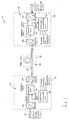
- the channel 10 comprises a transmitter unit 20, an optical fibre link 30 and a receiver unit 40 shown enclosed within dashed lines 25, 35, 45 respectively.
- the channel 10 operates by the transmitter unit 20 receiving payload data at its input from a sending client (not shown).
- the transmitter unit 20 proceeds to encode the payload data by arranging it into frames and multiframes to which are added overhead data to provide corresponding aggregate data.
- the aggregate data is conveyed as modulated optical radiation from the transmitter unit 20 through the fibre link 30 to the receiver unit 40.
- the receiver unit 40 receives the modulated radiation and derives therefrom the aggregate data.
- the receiver unit 40 decodes the aggregate data to separate out the overhead data from the payload data, and then outputs the payload data to a receiving client (not shown).
- the overhead data present in the aggregate data is interpreted by the receiver unit 40 and enables it to apply management and control functions. These functions will be described in more detail later and include path trace, automatic protection switching (APS), bit interleaved parity (BIP), forward and backward quality indication (FQI and BQI), forward and backward defect indication (FDI and BDI).
- APS automatic protection switching
- BIP
- the transmitter unit 20 includes a first optical-to-electrical converter 100, an overhead generator unit 105, an adapter unit 110 and a second electrical-to-optical converter 120.
- the first converter 100 is connected at its optical input to the sending client through an optical fibre 130.
- An electrical output from the converter 100 is connected to a first electrical input of the adapter 110.
- overhead data generated in the overhead unit 105 is conveyed through an electrical connection connecting the overhead unit 105 to a second electrical input of the adapter unit 110.
- An electrical output from the adapter unit 110 is connected to an electrical input of the second converter 120.
- the fibre link 30 is connected at its first end to an optical output of the second converter 120.
- the overhead generator unit 105 is also connected to overhead generator units of other channels, and also to local and regional management systems (not shown in Figure 1 ).
- the receiver unit 40 comprises a third optical-to-electrical converter 200, an adapter unit 210, a fourth electrical-to-optical converter 215 and an overhead generator unit 220.
- the third converter 200 is connected at its optical input to a second end of the fibre link 30.
- An electrical output of the converter 200 is connected to an electrical input of the adapter 210.
- the adapter 210 includes first and second electrical outputs; the first output is connected to an electrical input of the fourth converter 215 and the second output is connected to an input of the overhead interpreter unit 220.
- the interpreter unit 220 is also connected to interpreter units of other channels, to a local management system and also to the aforementioned regional management system (not shown in Figure 1 ).
- An optical output from the converter unit 215 is connected through an optical fibre to the receiving client (not shown).
- the first converter 100 receives payload data from the sending client through the fibre 130.
- the transmitter unit 20 is designed to accommodate payload data from the sending client at bit data rates of up to 10 Gbits/second and greater.
- the converter 100 converts the payload data into a corresponding electrical signal that propagates from the electrical output of the converter 100 to the first electrical input of the adapter unit 110.
- the overhead unit 105 receives management instructions from the local and regional management systems and generates corresponding overhead data that propagates to the second electrical input of the adapter unit 110.
- the adapter unit 110 then interleaves the overhead data with the payload data such that 31 bits of payload data are accompanied by 1 bit of overhead data in a fixed ratio of 31:1.
- the adapter unit 110 assembles the interleaved data into frames, each frame comprising 2048 bits of which 1984 bits and 64 bits correspond to payload data and overhead data respectively. Moreover, the adapter unit 110 further assembles frames into groups of eight frames, thereby generating corresponding multiframes. Structures of the frames and multiframes will be described in more detail later.
- the multiframes are output at the electrical output of the adapter unit 110 in the form of the aggregate data that propagates to the electrical input of the second converter 120.
- the converter 120 converts the aggregate data into corresponding digitally modulated optical radiation which is output at the optical output into the fibre link 30 along which the radiation propagates to the receiver unit 40; the converter 40 includes a modulated infra-red laser operable to output radiation at a wavelength in the order of 1550 nm.
- the third converter 200 receives the modulated radiation and converts it to a corresponding electrical signal that the adapter unit 210 receives at its electrical input; this conversion is performed by optical amplifiers, regenerators and associated photodetectors within the converter 200.
- the adapter unit 210 processes the electrical signal corresponding to the aggregate data by stripping out the overhead data therefrom and passing it to the interpreter unit 220.
- the adapter unit 210 further decodes the frames and multiframes to extract the payload data that is output from the adapter unit 210 to the electrical input of the fourth converter 215.
- the converter 215 converts the payload data and modulates it onto optical radiation which is output at the optical output of the converter 215 and propagates to the receiving client.
- the form of the aggregate data in the channel 10 is distinguished from conventional communication systems in that the number of bits of overhead data and payload data in the aggregate data is always in a fixed ratio. Moreover, justification is not employed with a consequence that blocks of data provided by the sending client are asynchronous to the frames and multiframes of the channel 10. As a consequence of the adapter unit 210 stripping out the overhead data and decoding the frames and multiframes, transmission from the sending client to the receiving client is transparent in the sense that the receiving client will be unaware that frames and multiframes are used to convey the payload data through the channel 10.
- bit error rate determination allows, in a communication system incorporating a plurality of channels similar to the channel 10, defective channels to be more easily identified and, if necessary, corresponding protection channels to be selected in substitution.
- a communication system can be constructed according to the invention that comprises a plurality of channels similar to the channel 10 where modulated optical radiation is optically multiplexed along a single optical fibre link.
- Such a system is illustrated in Figure 2 and indicated generally by 300.
- the system 300 comprises N transmitter units, for example transmitter units 20a, 20b corresponding to channels 1 and 2 respectively.
- Each transmitter unit 20 is connected at its optical input to a corresponding sending client, for example the channels 1 and 2 are connected to sending clients 1 and 2 respectively.
- the transmitter units 20 are interconnected at their associated overhead generator units 105 so that, for example, sending client 1 payload data can be directed through channel N in the event of channel 1 becoming defective as in protection switching.
- Optical outputs from the transmitter units 20 are connected to an optical multiplexer 310 which combines the outputs to provide a composite optical output.
- the composite output is connected to the first end of the fibre 150 of the fibre link 30.
- the second converters 120 of the transmitter units 20 in the system 300 are configured to output their optical radiation at mutually different wavelengths.
- the converters 120 of the channels 1, 2 and N can be configured to output optical radiation at nominal wavelengths of 1550, 1560 and 1600 nm respectively, although other wavelengths can alternatively be used if necessary.
- the fibre 150 is connected at its second end to an optical demultiplexer 320 comprising a plurality of Bragg grating optical filters, for example a filter 330, for isolating radiation components provided from the multiplexer 310 corresponding to each transmitter unit 20.
- the demultiplexer 320 is connected at its optical outputs to associated receiver units 40 that are in turn connected to associated receiving clients.
- the receiver units 40 are interconnected at their respective interpreter units 220 so that functions such as switching to a protection channel, for example channel N, can be implemented in the event of another channel developing a fault.
- payload data received from the sending clients is encoded in the transmitter units 20 to generate corresponding aggregate data thererat.
- the aggregate data of each transmitter unit 20 is modulated onto optical carrier radiation whose nominal wavelength is specific to each transmitter unit 20.
- the optical radiation output from the transmitter units 20 is optically combined in the multiplexer 310 to generate the composite radiation that propagates through the fibre link 30.
- the demultiplexer 320 receives the composite radiation at its optical input and filters out aggregate radiation corresponding to each transmitter unit 20.
- the aggregate radiation propagates to its respective receiver unit 40 that then decodes the aggregate data to provide payload data to its associated receiving client.
- the system 300 can be duplicated to provide an enlarged system comprising several multiplexers, demultiplexers and optical fibre links.
- Each transmitter unit and receiver unit in such an enlarged system can be connected to other transmitter units and receiver units respectively for providing functions such as protection switching in the event of a fibre link, a demultiplexer or a multiplexer become defective.
- Each channel in the system 300 adapts to the rate at which payload data is supplied from its respective sending client.
- the channels in the system 300 are capable of functioning mutually asynchronously.
- Such adaptation within the channels to the rates at which payload data is supplied by sending clients is performed within the adapter units 110, 210 of each channel.
- system 300 shown in Figure 3 is operable to provide communication links from the sending clients to the receiving client, it will be appreciated that bi-directional communication between the sending clients and the receiving clients is provided by including corresponding reverse directed channels (not shown) from the receiving clients to the sending clients, the reverse directed channels being of similar design to the channels illustrated in Figures 1 and 2 .
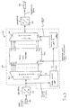
- the adapter unit 110 will be described in more detail with reference to Figure 3 .
- the ability of the channels of the system 300 to function mutually asynchronously circumvents the need for justification in the aggregate data, thereby enabling a fixed ratio of payload bits to overhead bits to be achieved which greatly simplifies overhead functions such as determination of bit error rate (BER), and also reduces jitter in the aggregate data propagating in the channel 10 and the system 300.
- BER bit error rate
- the adapter unit 110 shown included within a dashed line 490, comprises a 1-to-31 demultiplexer 500, a 32-to-1 multiplexer 510, a first phase locked loop (PLL1) 520, a second phase locked loop (PLL2) 530 and a data encoder 540.
- the encoder 540 is implemented as a field programmable logic device (FPLD), for example as manufactured by Xilinx Inc.
- the electrical output from the first converter 100 is connected to a serial data input of the demultiplexer 500 and to a reference input of the PLL1 520.
- a first output from the PLL1 520 is connected to a clocking input CLK of the demultiplexer 500.
- a second output from the PLL1 520 is connected to a reference input of the PLL2 530.
- the demultiplexer 500 comprises parallel outputs D 0 to D 30 which are connected to corresponding data inputs of the data encoder 540.
- the overhead unit 105 comprises an overhead data output connected to an overhead data input K 0 of the encoder 540.
- the encoder 540 further comprises parallel data outputs E 0 to E 31 connected to corresponding parallel inputs of the multiplexer 510.
- An output of the PLL2 530 is connected to a clocking input CLK of the multiplexer 510.
- the multiplexer 510 includes a multiplexed output connected to the electrical input of the second converter 120.
- the adapter unit 110 functions by receiving serial payload data from the first converter 100 at a bit rate of up to 10 Gbits/s or greater.
- the PLL1 520 synchronizes itself to the payload data and generates a corresponding synchronized clocking signal which clocks continuously even when the payload data remains at a particular logic state for several clock cycles.
- the PLL1 520 clocks both the demultiplexer 500 and the PLL2 530.
- the payload data is converted from a serial bit stream to 31-bit wide parallel words in the demultiplexer 500.
- the payload data is transferred in 31-bit words from the demultiplexer 500 to the encoder 540.
- the encoder 540 adds one bit of overhead data received from the overhead generator unit 105 to every 31 bits of payload data in a fixed ratio to provide output words at the outputs E 0 to E 31 .
- the output words are passed to the multiplexer 510 which converts the output words into a corresponding serial data stream, namely the aggregate data, that passes to the second converter 120 whereat it is modulated onto optical radiation for transmission along the fibre 150.
- Inclusion of the demultiplexer 500 provides the benefit that the encoder 540 receives data in the form of words and does not need to be capable of clocking at the rate of payload data which can approach 10 Gbits/s; the encoder 540 clocks at rates in the order of 300 MHz when the bit rate of payload data approaches 10 Gbits/s.
- the demultiplexer 500 is designed to be capable of handling up to 10 Gbits/s or greater serial data bit rates.
- Inclusion of the overhead data into the aggregate data means that the bit data rate in the aggregate data is 32 / 31 times greater than the payload traffic presented from the sending client to the adapter unit 110. It is the purpose of the PLL2 530 to provide a clocking signal at a rate F 2 which is frequency locked to the clocking signal at a rate F 1 provided from the PLL1 520. The clocking signal from the PLL2 530 clocks the multiplexer 510 at a rate 32 / 31 times greater than the demultiplexer 500 is clocked by the PLL1 520. Such a bit rate transformation prevents an accumulation of payload data in the adapter unit 540 which would occur if the demultiplexer 500 and multiplexer 510 were clocked at identical rates.
- the aggregate data is firstly loaded into a 1-to-32 demultiplexer operable to convert serial data into 32-bit word data, then the overhead bit is extracted from the 32-bit word data to yield a 31-bit word which is passed to a 31-to-1 bit multiplexer to convert the 31-bit word into corresponding serial payload data.
- the adapter unit 210 also incorporates two PLLs as shown in Figure 3 except that the second PLL connected to the multiplexer is operable to provide a 31 / 32 times frequency conversion.
- the data encoder 540 included within the adapter unit 110 is substituted with a decoder in the adapter unit 210 which is operable to output overhead data to its associated interpreter unit 220.
- a 1-to-16 demultiplexer 540 is used instead of the demultiplexer 500 in Figure 3 .
- a 16-to-1 multiplexer 550 is used instead of the multiplexer 510 in Figure 3 .
- an FPLD data encoder 560 including a buffer memory 570 is used instead of the encoder 540 in Figure 3 .
- payload data in the form of a serial bit stream passes from the converter 100 into the demultiplexer 540 which converts the serial stream into corresponding 16-bit parallel words.
- the words are loaded by the encoder 560 into its buffer memory 570 to provide payload data therein.
- the encoder 560 then adds an appropriate overhead bit to each concurrent group of 31 bits of payload data within the memory 570 to generate aggregate data therein and then proceeds to output the aggregate data in words of 16-bits length to the multiplexer 550.
- the multiplexer 550 converts the 16-bit words to a serial bit stream of aggregate data which is then output from the encoder unit 110 to the second converter 120 for modulation therein onto optical radiation for transmitting along the fibre 150.
- Bit rate conversion occurring at the adapter units 110, 120 circumvents the need to justify the aggregate data, thereby simplifying the aggregate data and enabling sub-node assessment of bit error rate to be made.
- the aggregate data is serial data and is punctuated into frames and multiframes by virtue of bit values of the overhead data added in a fixed ratio to the payload data at the adapter unit 110.
- Eight frames in sequence in the aggregate data form a multiframe.
- the structure of a frame is illustrated in Figure 5 and indicated by 600.
- Each frame 600 commences with an overhead bit A1 that is followed by 31 bits of sending client payload data (31 bits P/L) that, in turn, is followed by an overhead bit A2 and so on.
- an overhead bit A8 in the aggregate data is followed by 31 bits of payload data that, in turn, is followed by an overhead bit B1 and so on.
- the frame 600 terminates with an overhead bit H8 followed by 31 bits of payload data.
- each bit of overhead data in the frame 600 is accompanied by 31 bits of payload data in a fixed ratio of 1:31.
- the aggregate data corresponding to the frame 600 can be regarded conceptually as the frame 600 being read-out row-by-row, as represented by an arrow 610 indicating row direction and an arrow 620 indicating column direction.
- the frame 600 is thus read-out from its top lefthand corner (START) to its bottom right-hand corner (END) row-by-row to provide the aggregate data.
- the overhead bits A 1 to A8 form a byte A
- the overhead bits B1 to B8 form a byte B
- the overhead bits for each frame can be represented as illustrated in Table 1 as eight bytes; the payload data from the sending client is not shown in the table.
- Table 1 Overhead Byte A Overhead Byte B Overhead Byte C Overhead Byte D Overhead Byte E Overhead Byte F Overhead Byte G Overhead Byte H
- Eight frames similar to the frame 600 are output in sequence in the aggregate data to form a multiframe.
- the overhead bytes of the eight frames comprising the multiframe can be represented by symbols where byte A x corresponds to the overhead byte A of frame x where a subscript x is in a range of 1 to 8.
- a byte A 1 corresponds to an overhead byte A of the first frame in the multiframe
- a byte H 8 corresponds to an overhead byte H of the eighth frame in the multiframe.
- the overhead bytes of the multiframe can be arranged in tabular form as in Table 2.
- the overhead bytes appear in a sequence, although punctuated by payload data, such that byte A 1 is followed by byte B 1 and so on to byte H 1 followed by byte A 2 and so on until byte H 8 at the end of the multiframe.
- the units 105, 220 use the overhead bytes for performing a number of overhead functions which will now be described with reference to Figure 6 ; this diagram shows a representation of overhead bytes of a multiframe structure used in the channel 10 and the system 300.
- the overhead bytes perform different functions, for example as indicated by abbreviations in the diagram, namely: FAW: "frame alignment word”; MIC: “multiframe identity code”; BAL: “balancing byte”; SPA: “spare byte”; TTI: “trail trace identifier”; APS: “automatic protection channel”; FDI: “forward defect indication”; BDI: “backward defect indication”; FQI: “forward quality indicator”; BQI: “backward quality indicator”; PTI: “payload type indicator”; and BIP: "bit interleaved parity".
- the overhead generator unit 105 generates the overhead bytes shown in Figure 6 . Values of some of the overhead bytes are determined locally at the overhead unit 105 whereas others are generated in response to commands received from the aforementioned local and regional management systems, for example TTI values. In other words, the overhead bytes are generated on the basis of information provided either internally within the transmitter unit 20 or from the aforementioned management systems. These bytes are communicated in the aggregate data to the adapter unit 210 which isolates the overhead bytes and passes them to the interpreter unit 220 for interpretation.
- the interpreter unit 220 uses the overhead bytes FAW1, FAW2, FAW3, FAW4 to identify where multiframes start in the aggregate data, namely for synchronising to multiframes.
- these bytes FAW1, FAW 2, FAW3, FAW4 have fixed values of 1111 0110 b , 1111 0110 b , 0010 1000 b , 0010 1000 b respectively where a subscript b indicates a binary number.
- Alternative values can be used for these bytes FAW 1 to FAW4 provided that the values provide the channel 10 and system 300 with the capability of synchronising to multiframes.
- the multiframe identity code MIC is a byte value which is incremented by the overhead generator unit 105 for each subsequent multiframe. For example a first multiframe has a MIC value 0000 0001 b , a second multiframe following the first multiframe has a MIC value 0000 0010 b and so on; when the identity code reaches a value 1111 1111 b for the 255 th multiframe, the MIC resets to a 0000 0000 b value again for the 256 th multiframe and so on in a modulo 255 manner. Incrementation in other moduli, for example in modulo 8, is also possible for the MIC code instead of using modulo 255.
- the interpreter unit 220 is operable to monitor the identity code and ensure that correct incrementation occurs; any errors in incrementing the MIC are identified by the interpreter unit 220 as indicative of missing multiframes. Moreover, inclusion of the MIC code into the aggregate data assists the receiver unit 40 to synchronise to the aggregate data, namely frame alignment is improved thereby at the receiver unit 40.
- the MIC value can be incremented by more than 1 count for each subsequent multiframe, for example incrementation can be in steps of three counts so that a typical MIC counting sequence could be 1111 1110 b (decimal 254) for a first multiframe, 0000 0001 b (decimal 1) for a second multiframe, 0000 0100 b (decimal 4) for a third multiframe and so on.
- the interpreter unit 220 uses the balancing overhead bytes BAL for d.c. restoration purposes.
- the value of the balancing bytes are set by the overhead generator unit 105 so that for each of the frames 2 to 8 of the multiframe represented in Figure 6 , the number of 0's and 1's in its associated overhead bytes are equal.
- Such balancing is advantageous when photodetectors having their electrical outputs a.c. coupled to remove d.c. offset are employed in the channel 10 and system 300 for converting radiation modulated with the aggregate data into electrical signals for the adapter unit 210 and its associated interpreter unit 220.
- the multiframe in Figure 6 also includes spare bytes SPA which are unallocated initially but can be allocated by system users to perform additional functions after commissioning the system 300 if such functions are found to be necessary to assist system operation.
- the generator and interpreter units 105, 220 are software controlled and are therefore susceptible to being performance upgraded by software modification.
- the trail trace identifier overhead bytes TTI comprise a 16-byte string which is included from frame 2 overhead byte B 2 to frame 5 overhead byte D 5 as illustrated in Figure 6 .
- Bytes 2 to 16 of the string are user definable ASCII characters and byte 1 of the string includes a CRC-7 checksum value generated by the overhead unit 105 in accordance with an ITU communication specification G. 707 Annex B.
- the string is used by the system 300 to ensure that a receiving client is connected to its correct corresponding sending client.
- the automatic protection channel overhead bytes APS1 to APS4, namely frame 6 overhead bytes A 6 to D 6 . are used by the system 300 when a defective channel therein has to be bypassed and another channel of the system 300 allocated in substitution to convey its payload data.
- the interpreter unit 220 interprets these overhead bytes to determine whether or not its associated channel is to be bypassed and the identity of an alternative channel of the system 300 allocated in substitution.
- the overhead and interpreter units 105, 220 are operable in combination with the aforementioned local and regional management systems to determine interconnections within the system 300 when substitution occurs for routing payload data from an affected sending client to its associated receiving client.
- the forward defect indication overhead byte FDI namely frame 7 overhead byte A 7
- the forward defect indication overhead byte FDI is used in the channel 10 and system 300 to indicate downstream, namely on the receiving client's end of the fibre link 30, that a defect condition has been detected upstream, namely towards the corresponding sending client.
- the backward defect indication byte BDI namely frame 7 overhead byte B 7
- FDI and BDI overhead bytes thereby enable the location of a defect in the system 300 to be easily and rapidly identified.
- the forward quality indication overhead byte FQI namely frame 7 overhead byte C 7
- FQI is used for indicating downstream an error occurring upstream.
- the backward quality indication byte BQI namely frame 7 overhead byte D 7
- BQI is used for conveying a bit error count for the payload data of the preceding multiframe.
- the payload type indicator overhead byte PTI namely frame overhead byte A 8 , is used for indicating composition of the payload data or the maintenance status of a communication path conveying the multiframe and its associated payload data.
- interpretations for the overhead byte PTI are according to Table 3.
- bit interleaved parity overhead bytes BIP include a BIP-8 parity check value; a detailed definition is provided in ITU standard G. 707.
- Each frame has its associated BIP parity value which provides a parity check for the payload data of the frame.
- BIP byte allocation to each frame reduces the need for high-speed memory at the receiving unit 40 of the channel 10.
- distributing the BIP overhead bytes in the frames is preferable to concatenating the BIP bytes together in the multiframe.
- the BIP code provides a direct indication of bit error rate in the payload data because the ration of the number of the payload bits to the number of overhead bits is maintained in the system 300 in a fixed ratio.
- the adapter unit 110 can be modified so that the ratio is in a range of 1:2 bits to 1:100 bits depending upon the degree of overhead control required.
- An important point is that the ratio should be fixed and not dynamically variable as in prior art communication systems where justification is employed.
- the number of frames comprising a multiframe can be altered from eight frames comprising a multiframe as aforementioned.
- the number of frames forming a multiframe can be varied in a range of 2 to 100, although including more than 50 frames in a multiframe makes synchronisation more difficult at the receiver unit 40.
- positions of the overhead bytes performing specific functions can be altered provided they continue to perform their associated functions, for example, positions of the MIC and PTI overhead bytes can be exchanged in a modified version of the multiframe.
- the BIP overhead bytes of each frame can be arranged to be included at the last overhead byte of each frame, for example at overhead byte H 1 for frame 1.
- the fibre link 30 can comprise one or more optical fibres.
- the fibre link 30 can be substituted with a radio link, for example a satellite microwave link.
- the fibre link 30 can be replaced with one or more coaxial cable wire connections; such coaxial links generally have a lower data carrying capacity compared to optical fibre connections.
Landscapes
- Engineering & Computer Science (AREA)
- Computer Networks & Wireless Communication (AREA)
- Signal Processing (AREA)
- Time-Division Multiplex Systems (AREA)
- Communication Control (AREA)
- Optical Communication System (AREA)
- Mobile Radio Communication Systems (AREA)
- Synchronisation In Digital Transmission Systems (AREA)
- Detection And Prevention Of Errors In Transmission (AREA)
Claims (26)
- Procédé de communication de données dans des systèmes de communication (300), chaque système incluant au moins un canal (10) comprenant des moyens d'émission (20), des moyens de réception (40) et des moyens de transport de données (30) pour transporter des données des moyens d'émission (20) vers les moyens de réception (40), le procédé comprenant les étapes consistant à :(a) combiner des données de charge utile et des données de préfixe au niveau des moyens d'émission (20) afin de former des données agrégées (600) à cet emplacement en vue de la transmission aux moyens de réception (40), les données agrégées (600) étant divisées en multitrames ayant une pluralité de trames dans lesquelles le nombre de bits de données de préfixe est dans un rapport fixe par rapport au nombre de bits de données de charge utile ;(b) transmettre les données agrégées (600) des moyens d'émission (20) aux moyens de réception (40) via les moyens de transport (30) ;(c) recevoir les données agrégées (600) au niveau des moyens de réception (40), décoder les données agrégées afin d'isoler les données de préfixe des données de charge utile à cet emplacement, et interpréter les données de préfixe pour commander et gérer les données de charge utile à l'intérieur du système (300),caractérisé en ce que les moyens de transmission (20) sont mis en fonctionnement afin de générer les données agrégées (600) à un taux qui est supérieur au taux de réception des données de charge utile à cet emplacement de essentiellement une fraction (Rp+Ro) / (Rp), où Rp est le taux de réception des données de charge utile au niveau des moyens d'émission (20) et Ro est le taux auquel les données de préfixe sont ajoutées au niveau des moyens d'émission (20) afin de générer les données agrégées (600),
caractérisé par
le rapport du nombre de bits de données de préfixe par rapport au nombre de bits de charge utile étant fixe pour différents taux de réception des données de charge utile (Rp). - Procédé selon la revendication 1, dans lequel le rapport fixe des bits de charge utile par rapport aux bits de préfixe est compris dans une plage de 2:1 à 100:1.
- Procédé selon la revendication 1 ou 2, dans lequel le rapport fixe des bits de charge utile par rapport aux bits de préfixe est de 31 :1.
- Procédé selon la revendication 1, 2 ou 3, dans lequel le système est mis en fonctionnement afin de ne pas appliquer de justification supplémentaire aux données de charge utile lors de la génération des données agrégées (600).
- Procédé selon la revendication 1, 2, 3 ou 4, dans lequel le nombre d'octets de préfixe indicateurs d'une occurrence de taux d'erreur à l'intérieur des données agrégées par rapport au nombre d'octets de charge utile est dans un rapport fixe, fournissant ainsi une densité fixe d'octets de taux d'erreur par rapport aux octets de charge utile.
- Procédé selon la revendication 5, dans lequel le nombre d'octets de préfixe indicateurs d'une occurrence de taux d'erreur par rapport au nombre d'octets de charge utile correspondants est dans un rapport fixe de 1:248.
- Procédé selon une quelconque des revendications 1 à 6, dans lequel le système (300) inclut une pluralité de canaux (20a, 20b, 40a, 40b), chaque canal (20a, 20b, 40a, 40b) étant capable de s'adapter au débit de ses données de charge utile associées, les canaux (20a, 20b, 40a, 40b) étant ainsi capables de fonctionner de manière mutuellement asynchrone.
- Procédé selon une quelconque des revendications précédentes, dans lequel les données de préfixe et les données de charge utile sont entrelacées dans les données agrégées (600).
- Procédé selon une quelconque des revendications précédentes, dans lequel les trames et multitrames sont identifiables au niveau du moyen de réception (40) en interprétant la position des données de préfixe à l'intérieur des données agrégées.
- Procédé selon la revendication 9, dans lequel chaque multitrame comprend entre 2 et 100 trames.
- Procédé selon la revendication 9 ou 10, dans lequel chaque multitrame comprend 8 trames.
- Procédé selon la revendication 9, 10 ou 11, dans lequel les données de préfixe associées à chaque multitrame comprennent un code de synchronisation (FAW) pour assister les moyens de réception dans le cadre de la synchronisation aux multitrames.
- Procédé selon la revendication 12 ou 13, dans lequel le code de synchronisation comprend quatre octets de synchronisation (FAW 1 à 4) dans les données de préfixe.
- Procédé selon la revendication 12 ou 13, dans lequel les quatre octets de synchronisation (FAW 1 à 4) ont des valeurs binaires de 1111 0110b, 1111 0110b, 0010 1000b et 0010 1000b qui leur sont respectivement allouées.
- Procédé selon une quelconque des revendications 9 à 14, dans lequel les données de préfixe associées à chaque multitrame comprennent un code d'identité (MIC) à utiliser lors de l'identification de la multitrame.
- Procédé selon la revendication 15, dans lequel le code d'identité (MIC) est incrémenté pour des multitrames successives.
- Procédé selon la revendication 15 ou 16, dans lequel le code d'identité (MIC) est incrémenté de manière modulo.
- Procédé selon la revendication 16 ou 17, dans lequel le code d'identité (MIC) est incrémenté dans des étapes d'une pluralité de comptages pour des multitrames successives.
- Procédé selon la revendication 16, 17 ou 18, dans lequel les moyens de réception sont mis en fonctionnement afin de déterminer si ou non des multitrames sont manquantes en surveillant que le code d'identité (MIC) est incrémenté de manière consistante de multitrame à multitrame.
- Procédé selon une quelconque des revendications 9 à 19, dans lequel les données de préfixe associées à chaque multitrame comprennent un code d'équilibrage (BAL) pour garantir que les octets de préfixe associés à la multitrame incluent essentiellement des nombres égaux de 0's et 1's.
- Procédé selon une quelconque des revendications 9 à 20, dans lequel les données de préfixe associées à chaque multitrame comprennent un code d'identification de trace de chemin (TTI) à utiliser par les moyens de réception pour confirmer si ou non ils sont connectés à leurs moyens d'émission (20) corrects correspondants.
- Procédé selon une quelconque des revendications 9 à 21, dans lequel les données de préfixe associées à chaque multitrame comprennent un code de commutation de protection automatique (APS) pour enjoindre au système (300) d'utiliser des canaux alternatifs pour transporter les données de charge utile en cas de défaillance de canal à l'intérieur du système (300).
- Procédé selon une quelconque des revendications 9 à 22, dans lequel les données de préfixe associées à chaque multitrame comprennent un code de parité avec entrelacement de bits (BIP) pour chaque trame de la multitrame, le code de parité avec entrelacement étant utilisable par les moyens de réception (40) pour détecter l'occurrence d'une corruption des données de charge utile associées à la trame.
- Procédé selon une quelconque des revendications 9 à 23, dans lequel les données de préfixe associées à chaque multitrame comprennent un code d'indicateur de type de charge utile (PTI) indiquant le débit de charge utile entrant dans les moyens d'émission (20).
- Procédé selon une quelconque des revendications précédentes, dans lequel les moyens d'émission (20) sont mis en fonctionnement afin de recevoir les données de charge utile comme des données sérielles et de les convertir en données parallèles (D0 à D30) en vue d'une combinaison avec les données de préfixe (K0) afin de générer les données agrégées (600) comme des données sérielles en vue d'une transmission via les moyens de transport (30).
- Système de communication (300), comprenant au moins un canal (10) comprenant des moyens d'émission (20), des moyens de réception (40) et des moyens de transport de données (30) pour transporter des données des moyens d'émission (20) vers les moyens de réception (40), dans lequel :(a) les moyens d'émission sont mis en fonctionnement afin de combiner des données de charge utile et des données de préfixe afin de former des données agrégées (600) à cet emplacement en vue de la transmission aux moyens de réception (40), les données agrégées (600) étant divisées en multitrames ayant une pluralité de trames dans lesquelles le nombre de bits de données de préfixe est dans un rapport fixe par rapport au nombre de bits de données de charge utile ;(b) les moyens d'émission sont mis en fonctionnement afin de transmettre les données agrégées (600) aux moyens de réception (40) via les moyens de transport (30) ;(c) les moyens de réception sont mis en fonctionnement afin de recevoir les données agrégées (600), décoder les données agrégées afin d'isoler les données de préfixe des données de charge utile à cet emplacement, et interpréter les données de préfixe pour commander et gérer les données de charge utile à l'intérieur du système (300), les moyens d'émission (20) étant mis en fonctionnement afin de générer les données agrégées (600) à un taux qui est supérieur au taux de réception des données de charge utile à cet emplacement de essentiellement une fraction (Rp+Ro) / (Rp), où Rp est le taux de réception des données de charge utile au niveau des moyens d'émission (20) et Ro est le taux auquel les données de préfixe sont ajoutées au niveau des moyens d'émission (20) afin de générer les données agrégées (600), caractérisé en ce que les moyens d'émission sont mis en fonctionnement afin de maintenir le rapport du nombre de bits de données de préfixe fixe pour des taux de réception différents des données de charge utile (Rp).
Priority Applications (3)
| Application Number | Priority Date | Filing Date | Title |
|---|---|---|---|
| EP08166016.9A EP2009824B1 (fr) | 2000-01-14 | 2000-12-07 | Procédé de communication de données dans des systèmes de communication |
| DK08166016.9T DK2009824T3 (en) | 2000-01-14 | 2000-12-07 | PROCEDURE FOR COMMUNICATING DATA IN COMMUNICATION SYSTEMS |
| EP09166999.4A EP2109239B1 (fr) | 2000-01-14 | 2000-12-07 | Procédé de communication de données dans des systèmes de communication |
Applications Claiming Priority (2)
| Application Number | Priority Date | Filing Date | Title |
|---|---|---|---|
| GB0000791A GB2358332B (en) | 2000-01-14 | 2000-01-14 | Method of communicating data in a communication system |
| GB0000791 | 2000-01-14 |
Related Child Applications (2)
| Application Number | Title | Priority Date | Filing Date |
|---|---|---|---|
| EP08166016.9A Division EP2009824B1 (fr) | 2000-01-14 | 2000-12-07 | Procédé de communication de données dans des systèmes de communication |
| EP09166999.4A Division EP2109239B1 (fr) | 2000-01-14 | 2000-12-07 | Procédé de communication de données dans des systèmes de communication |
Publications (3)
| Publication Number | Publication Date |
|---|---|
| EP1117202A2 EP1117202A2 (fr) | 2001-07-18 |
| EP1117202A3 EP1117202A3 (fr) | 2006-08-02 |
| EP1117202B1 true EP1117202B1 (fr) | 2008-10-08 |
Family
ID=9883657
Family Applications (3)
| Application Number | Title | Priority Date | Filing Date |
|---|---|---|---|
| EP09166999.4A Expired - Lifetime EP2109239B1 (fr) | 2000-01-14 | 2000-12-07 | Procédé de communication de données dans des systèmes de communication |
| EP00310903A Revoked EP1117202B1 (fr) | 2000-01-14 | 2000-12-07 | Procédé de communication de données dans des systèmes de communication |
| EP08166016.9A Expired - Lifetime EP2009824B1 (fr) | 2000-01-14 | 2000-12-07 | Procédé de communication de données dans des systèmes de communication |
Family Applications Before (1)
| Application Number | Title | Priority Date | Filing Date |
|---|---|---|---|
| EP09166999.4A Expired - Lifetime EP2109239B1 (fr) | 2000-01-14 | 2000-12-07 | Procédé de communication de données dans des systèmes de communication |
Family Applications After (1)
| Application Number | Title | Priority Date | Filing Date |
|---|---|---|---|
| EP08166016.9A Expired - Lifetime EP2009824B1 (fr) | 2000-01-14 | 2000-12-07 | Procédé de communication de données dans des systèmes de communication |
Country Status (14)
| Country | Link |
|---|---|
| US (1) | US6810046B2 (fr) |
| EP (3) | EP2109239B1 (fr) |
| JP (2) | JP4846101B2 (fr) |
| CN (1) | CN1252960C (fr) |
| AT (1) | ATE410846T1 (fr) |
| AU (1) | AU1369401A (fr) |
| DE (1) | DE60040452D1 (fr) |
| DK (2) | DK2009824T3 (fr) |
| ES (3) | ES2526357T3 (fr) |
| GB (1) | GB2358332B (fr) |
| NO (1) | NO20010225L (fr) |
| PT (2) | PT2109239E (fr) |
| RU (1) | RU2001101418A (fr) |
| ZA (1) | ZA200007323B (fr) |
Families Citing this family (52)
| Publication number | Priority date | Publication date | Assignee | Title |
|---|---|---|---|---|
| US7382736B2 (en) | 1999-01-12 | 2008-06-03 | Mcdata Corporation | Method for scoring queued frames for selective transmission through a switch |
| GB2366971A (en) * | 2000-09-13 | 2002-03-20 | Marconi Comm Ltd | Bit and frame synchronisation |
| US7236490B2 (en) | 2000-11-17 | 2007-06-26 | Foundry Networks, Inc. | Backplane interface adapter |
| US7596139B2 (en) | 2000-11-17 | 2009-09-29 | Foundry Networks, Inc. | Backplane interface adapter with error control and redundant fabric |
| US7002980B1 (en) | 2000-12-19 | 2006-02-21 | Chiaro Networks, Ltd. | System and method for router queue and congestion management |
| US20020085591A1 (en) * | 2001-01-03 | 2002-07-04 | Michael Mesh | Fiber optic communication system |
| US7016378B1 (en) * | 2001-01-26 | 2006-03-21 | Ciena Corporation | Method and system for automatically provisioning an overhead byte |
| US7218636B2 (en) * | 2001-06-13 | 2007-05-15 | Inrange Technology Corporation | Method and apparatus for rendering a cell-based switch useful for frame based application protocols |
| US7092361B2 (en) * | 2001-12-17 | 2006-08-15 | Alcatel Canada Inc. | System and method for transmission of operations, administration and maintenance packets between ATM and switching networks upon failures |
| AU2003214677B2 (en) * | 2002-03-27 | 2005-12-22 | Samsung Electronics Co., Ltd. | Apparatus and Method for Receiving Packet Data Control Channel in a Mobile Communication System |
| JP3851836B2 (ja) | 2002-04-19 | 2006-11-29 | 富士通株式会社 | 波長多重伝送システム及び波長多重伝送装置 |
| US20120155466A1 (en) | 2002-05-06 | 2012-06-21 | Ian Edward Davis | Method and apparatus for efficiently processing data packets in a computer network |
| US7468975B1 (en) | 2002-05-06 | 2008-12-23 | Foundry Networks, Inc. | Flexible method for processing data packets in a network routing system for enhanced efficiency and monitoring capability |
| US7187687B1 (en) | 2002-05-06 | 2007-03-06 | Foundry Networks, Inc. | Pipeline method and system for switching packets |
| US7649885B1 (en) | 2002-05-06 | 2010-01-19 | Foundry Networks, Inc. | Network routing system for enhanced efficiency and monitoring capability |
| US7266117B1 (en) | 2002-05-06 | 2007-09-04 | Foundry Networks, Inc. | System architecture for very fast ethernet blade |
| US7111226B1 (en) * | 2002-05-31 | 2006-09-19 | Broadcom Corporation | Communication decoder employing single trellis to support multiple code rates and/or multiple modulations |
| US7313097B2 (en) * | 2002-08-06 | 2007-12-25 | Broadcom Corporation | Loop back testing structure for high-speed serial bit stream TX and RX chip set |
| US6901072B1 (en) | 2003-05-15 | 2005-05-31 | Foundry Networks, Inc. | System and method for high speed packet transmission implementing dual transmit and receive pipelines |
| US7817659B2 (en) * | 2004-03-26 | 2010-10-19 | Foundry Networks, Llc | Method and apparatus for aggregating input data streams |
| EP1585244B1 (fr) * | 2004-04-05 | 2009-06-03 | Alcatel Lucent | Division fonctionnelle d' unité matérielle dans une plate-forme de système d'un élément de réseau de télécommunication |
| US7535842B1 (en) * | 2004-04-09 | 2009-05-19 | Nortel Networks Limited | Method and system for merging bandwidth in multiplexing flows |
| US8730961B1 (en) | 2004-04-26 | 2014-05-20 | Foundry Networks, Llc | System and method for optimizing router lookup |
| CN100349390C (zh) | 2004-08-11 | 2007-11-14 | 华为技术有限公司 | 光传送网中传输低速率业务信号的方法及其装置 |
| US7657703B1 (en) | 2004-10-29 | 2010-02-02 | Foundry Networks, Inc. | Double density content addressable memory (CAM) lookup scheme |
| CN100411347C (zh) * | 2004-11-30 | 2008-08-13 | 华为技术有限公司 | 一种数据通信信道带宽自协商方法 |
| CN1791057B (zh) * | 2004-12-15 | 2011-06-15 | 华为技术有限公司 | 在光传送网中传输数据业务的方法及其装置 |
| US8448162B2 (en) | 2005-12-28 | 2013-05-21 | Foundry Networks, Llc | Hitless software upgrades |
| CN100512309C (zh) * | 2006-02-27 | 2009-07-08 | 华为技术有限公司 | 一种开销的传输方法 |
| US7903654B2 (en) | 2006-08-22 | 2011-03-08 | Foundry Networks, Llc | System and method for ECMP load sharing |
| US8238255B2 (en) | 2006-11-22 | 2012-08-07 | Foundry Networks, Llc | Recovering from failures without impact on data traffic in a shared bus architecture |
| US8395996B2 (en) | 2007-01-11 | 2013-03-12 | Foundry Networks, Llc | Techniques for processing incoming failure detection protocol packets |
| US7605737B2 (en) * | 2007-03-08 | 2009-10-20 | Texas Instruments Incorporated | Data encoding in a clocked data interface |
| US8037399B2 (en) | 2007-07-18 | 2011-10-11 | Foundry Networks, Llc | Techniques for segmented CRC design in high speed networks |
| US8271859B2 (en) | 2007-07-18 | 2012-09-18 | Foundry Networks Llc | Segmented CRC design in high speed networks |
| US8149839B1 (en) | 2007-09-26 | 2012-04-03 | Foundry Networks, Llc | Selection of trunk ports and paths using rotation |
| JP2009194581A (ja) * | 2008-02-14 | 2009-08-27 | Nec Corp | フレーム復元方法、フレーム復元回路及びフレーム復元プログラム |
| CN101645748B (zh) * | 2008-08-05 | 2012-06-06 | 华为技术有限公司 | 下行复帧的传输方法及装置 |
| US8300584B2 (en) | 2009-05-11 | 2012-10-30 | Alcatel Lucent | System and method for cell-edge performance management in wireless systems using distributed scheduling |
| US8090901B2 (en) | 2009-05-14 | 2012-01-03 | Brocade Communications Systems, Inc. | TCAM management approach that minimize movements |
| US8599850B2 (en) | 2009-09-21 | 2013-12-03 | Brocade Communications Systems, Inc. | Provisioning single or multistage networks using ethernet service instances (ESIs) |
| US9065625B2 (en) * | 2012-02-24 | 2015-06-23 | Raytheon Applied Signal Technology, Inc. | Impaired carrier coding |
| JP5863595B2 (ja) * | 2012-08-13 | 2016-02-16 | 日本電信電話株式会社 | タイムスロットインタリーブ伝送方法及びタイムスロットインタリーブ伝送システム |
| US8976678B2 (en) | 2012-11-30 | 2015-03-10 | Electro-Motive Diesel, Inc. | Multiple line communications for locomotive consist |
| US9071338B2 (en) | 2012-11-30 | 2015-06-30 | Electro-Motive Diesel, Inc. | Reliable data transfer for locomotive consist communications |
| US9078256B2 (en) | 2012-11-30 | 2015-07-07 | Electro-Motive Diesel, Inc. | Data communication systems and methods for locomotive consists |
| US9019918B2 (en) | 2012-11-30 | 2015-04-28 | Electro-Motive Diesel, Inc. | Transmission spectrum selection for locomotive consist communications |
| US9001683B2 (en) | 2012-11-30 | 2015-04-07 | Electro-Motive Diesel, Inc. | Selective routing of communications in locomotive consist |
| US9252886B2 (en) * | 2013-01-24 | 2016-02-02 | Sumitomo Electric Industries, Ltd. | Optical transmitter |
| CN103248584B (zh) * | 2013-04-27 | 2016-12-28 | 华为技术有限公司 | 一种通信方法及装置 |
| CN110830143B (zh) * | 2018-08-13 | 2022-03-25 | 中兴通讯股份有限公司 | 一种业务传输方法及装置、光传送网设备、存储介质 |
| US12407445B2 (en) * | 2022-01-21 | 2025-09-02 | Hughes Network Systems, Llc | Systems and methods for improving communication throughput |
Family Cites Families (16)
| Publication number | Priority date | Publication date | Assignee | Title |
|---|---|---|---|---|
| US4501000A (en) * | 1981-07-27 | 1985-02-19 | Sony Corporation | Method of coding binary data |
| JPS61171243A (ja) * | 1985-01-25 | 1986-08-01 | Fujitsu Ltd | 多重チヤンネルフレ−ムのタイムスロツト割当方式 |
| JPS6364435A (ja) * | 1986-09-05 | 1988-03-22 | Hitachi Ltd | マルチスロットアクセス環状伝送装置及び方法 |
| JP3025968B2 (ja) * | 1988-02-10 | 2000-03-27 | 日本電信電話株式会社 | セル多重伝送方式 |
| US5432800A (en) * | 1991-10-29 | 1995-07-11 | Hitachi, Ltd. | Methods and apparatuses for transmission and reception of information signals |
| US5475716A (en) * | 1994-01-18 | 1995-12-12 | Gi Corporation | Method for communicating block coded digital data with associated synchronization/control data |
| US5579323A (en) | 1994-07-22 | 1996-11-26 | Alcatel Network Systems, Inc. | Virtual tributary/tributary unit transport method and apparatus |
| US5490142A (en) * | 1994-09-30 | 1996-02-06 | Alcatel Network Systems, Inc. | VT group optical extension interface and VT group optical extension format method |
| JP2773689B2 (ja) * | 1995-06-23 | 1998-07-09 | 日本電気株式会社 | Atmアダプテーションレイヤにおけるデータ変換方式 |
| JPH09298522A (ja) * | 1996-04-26 | 1997-11-18 | Matsushita Electric Ind Co Ltd | 高速信号と低速信号の多重方法 |
| US5787074A (en) * | 1996-06-28 | 1998-07-28 | Mci Communications Corporation | System and method for monitoring point activation |
| JP3774042B2 (ja) * | 1997-09-11 | 2006-05-10 | 富士通株式会社 | ショートセル多重装置 |
| US6292495B1 (en) * | 1998-04-10 | 2001-09-18 | Cisco Technology, Inc. | Segmented permanent virtual circuits |
| US6307867B1 (en) * | 1998-05-14 | 2001-10-23 | Telefonaktiebolaget Lm Ericsson (Publ) | Data transmission over a communications link with variable transmission rates |
| FI108824B (fi) * | 1998-06-03 | 2002-03-28 | Nokia Corp | Datasiirtomenetelmiä tietoliikennejärjestelmässä |
| US6650630B1 (en) * | 1999-06-25 | 2003-11-18 | Telefonaktiebolaget Lm Ericsson (Publ) | Resource management and traffic control in time-division-duplex communication systems |
-
2000
- 2000-01-14 GB GB0000791A patent/GB2358332B/en not_active Expired - Lifetime
- 2000-12-07 ES ES09166999.4T patent/ES2526357T3/es not_active Expired - Lifetime
- 2000-12-07 EP EP09166999.4A patent/EP2109239B1/fr not_active Expired - Lifetime
- 2000-12-07 EP EP00310903A patent/EP1117202B1/fr not_active Revoked
- 2000-12-07 DE DE60040452T patent/DE60040452D1/de not_active Expired - Lifetime
- 2000-12-07 EP EP08166016.9A patent/EP2009824B1/fr not_active Expired - Lifetime
- 2000-12-07 PT PT91669994T patent/PT2109239E/pt unknown
- 2000-12-07 PT PT81660169T patent/PT2009824E/pt unknown
- 2000-12-07 DK DK08166016.9T patent/DK2009824T3/en active
- 2000-12-07 AT AT00310903T patent/ATE410846T1/de not_active IP Right Cessation
- 2000-12-07 ES ES00310903T patent/ES2313873T3/es not_active Expired - Lifetime
- 2000-12-07 DK DK09166999.4T patent/DK2109239T3/en active
- 2000-12-07 ES ES08166016.9T patent/ES2562604T3/es not_active Expired - Lifetime
- 2000-12-08 ZA ZA200007323A patent/ZA200007323B/xx unknown
- 2000-12-28 US US09/751,294 patent/US6810046B2/en not_active Expired - Lifetime
-
2001
- 2001-01-12 AU AU13694/01A patent/AU1369401A/en not_active Abandoned
- 2001-01-12 NO NO20010225A patent/NO20010225L/no not_active Application Discontinuation
- 2001-01-12 RU RU2001101418/09A patent/RU2001101418A/ru not_active Application Discontinuation
- 2001-01-15 JP JP2001006564A patent/JP4846101B2/ja not_active Expired - Lifetime
- 2001-01-15 CN CNB011015195A patent/CN1252960C/zh not_active Ceased
-
2011
- 2011-05-02 JP JP2011102780A patent/JP5378446B2/ja not_active Expired - Lifetime
Also Published As
| Publication number | Publication date |
|---|---|
| EP2009824A3 (fr) | 2009-03-11 |
| EP2009824B1 (fr) | 2015-11-11 |
| ES2313873T3 (es) | 2009-03-16 |
| ES2562604T3 (es) | 2016-03-07 |
| EP2009824A2 (fr) | 2008-12-31 |
| PT2109239E (pt) | 2015-01-02 |
| GB2358332B (en) | 2002-05-29 |
| NO20010225D0 (no) | 2001-01-12 |
| GB0000791D0 (en) | 2000-03-08 |
| US6810046B2 (en) | 2004-10-26 |
| DE60040452D1 (de) | 2008-11-20 |
| ATE410846T1 (de) | 2008-10-15 |
| AU1369401A (en) | 2001-07-19 |
| NO20010225L (no) | 2001-07-16 |
| CN1306351A (zh) | 2001-08-01 |
| HK1036892A1 (en) | 2002-01-18 |
| JP2001244907A (ja) | 2001-09-07 |
| JP5378446B2 (ja) | 2013-12-25 |
| US20020031146A1 (en) | 2002-03-14 |
| DK2109239T3 (en) | 2015-01-05 |
| JP2011211718A (ja) | 2011-10-20 |
| ZA200007323B (en) | 2001-06-13 |
| ES2526357T3 (es) | 2015-01-09 |
| EP1117202A2 (fr) | 2001-07-18 |
| GB2358332A (en) | 2001-07-18 |
| EP2109239B1 (fr) | 2014-10-22 |
| JP4846101B2 (ja) | 2011-12-28 |
| PT2009824E (pt) | 2016-01-20 |
| RU2001101418A (ru) | 2002-12-20 |
| EP1117202A3 (fr) | 2006-08-02 |
| EP2109239A3 (fr) | 2010-02-17 |
| DK2009824T3 (en) | 2016-02-15 |
| EP2109239A2 (fr) | 2009-10-14 |
| CN1252960C (zh) | 2006-04-19 |
Similar Documents
| Publication | Publication Date | Title |
|---|---|---|
| EP1117202B1 (fr) | Procédé de communication de données dans des systèmes de communication | |
| EP0874487B1 (fr) | Transmission transparente dans un système de télécommunication | |
| US10097480B2 (en) | Time transfer systems and methods over flexible ethernet | |
| RU2331157C2 (ru) | Способ, устройство и система для оптической связи | |
| EP0874488B1 (fr) | Multiplexeur/demultiplexeur transparent | |
| JP5071963B2 (ja) | デジタル伝送システム、およびデジタル伝送方法 | |
| US7555008B2 (en) | Method and apparatus for providing a Gigabit Ethernet circuit pack | |
| AU740763B2 (en) | Data transmission in an SDH network | |
| JPH11331132A (ja) | 光伝送システム及び光伝送装置 | |
| US6870860B1 (en) | Semi-transparent time division multiplexer/demultiplexer | |
| US20090245292A1 (en) | Clock recovery apparatus and method | |
| US6594047B1 (en) | Apparatus and method for providing optical channel overhead in optical transport networks | |
| ITMI20000545A1 (it) | Metodo ed apparato per trasmettere/ricevere segnali digitali di livello stm-4(sdh) o sts-12(sonet) su due portanti rf in una sezione di rige | |
| US7526197B2 (en) | Utilizing the protecting bandwidth in a SONET network | |
| US7292608B1 (en) | Method and apparatus for transferring synchronous optical network/synchronous digital hierarchy(SONET/SDH) frames on parallel transmission links | |
| US7002957B2 (en) | Method of transporting frames of information between parts of a network through an intermediate network | |
| US7126943B2 (en) | Method and apparatus for interfacing a parallel connection | |
| US6901082B1 (en) | Method and apparatus for communicating information | |
| US6915348B1 (en) | Validation of a connection between arbitrary end-points in a communications network using an augmented SPE | |
| US7162536B1 (en) | Validation of a connection between arbitrary end-nodes in a communications network | |
| JP4941547B2 (ja) | 光伝送装置及び光伝送方法 |
Legal Events
| Date | Code | Title | Description |
|---|---|---|---|
| PUAI | Public reference made under article 153(3) epc to a published international application that has entered the european phase |
Free format text: ORIGINAL CODE: 0009012 |
|
| AK | Designated contracting states |
Kind code of ref document: A2 Designated state(s): AT BE CH CY DE DK ES FI FR GB GR IE IT LI LU MC NL PT SE TR |
|
| AX | Request for extension of the european patent |
Free format text: AL;LT;LV;MK;RO;SI |
|
| RAP1 | Party data changed (applicant data changed or rights of an application transferred) |
Owner name: MARCONI UK INTELLECTUAL PROPERTY LTD |
|
| PUAL | Search report despatched |
Free format text: ORIGINAL CODE: 0009013 |
|
| AK | Designated contracting states |
Kind code of ref document: A3 Designated state(s): AT BE CH CY DE DK ES FI FR GB GR IE IT LI LU MC NL PT SE TR |
|
| AX | Request for extension of the european patent |
Extension state: AL LT LV MK RO SI |
|
| RAP1 | Party data changed (applicant data changed or rights of an application transferred) |
Owner name: M(DGP1) LTD |
|
| RAP1 | Party data changed (applicant data changed or rights of an application transferred) |
Owner name: ERICSSON AB |
|
| RAP1 | Party data changed (applicant data changed or rights of an application transferred) |
Owner name: ERICSSON AB |
|
| 17P | Request for examination filed |
Effective date: 20070201 |
|
| AKX | Designation fees paid |
Designated state(s): AT BE CH CY DE DK ES FI FR GB GR IE IT LI LU MC NL PT SE TR |
|
| 17Q | First examination report despatched |
Effective date: 20070326 |
|
| GRAP | Despatch of communication of intention to grant a patent |
Free format text: ORIGINAL CODE: EPIDOSNIGR1 |
|
| GRAS | Grant fee paid |
Free format text: ORIGINAL CODE: EPIDOSNIGR3 |
|
| GRAA | (expected) grant |
Free format text: ORIGINAL CODE: 0009210 |
|
| AK | Designated contracting states |
Kind code of ref document: B1 Designated state(s): AT BE CH CY DE DK ES FI FR GB GR IE IT LI LU MC NL PT SE TR |
|
| REG | Reference to a national code |
Ref country code: GB Ref legal event code: FG4D |
|
| REG | Reference to a national code |
Ref country code: CH Ref legal event code: EP |
|
| REG | Reference to a national code |
Ref country code: IE Ref legal event code: FG4D |
|
| REG | Reference to a national code |
Ref country code: CH Ref legal event code: NV Representative=s name: ISLER & PEDRAZZINI AG |
|
| REF | Corresponds to: |
Ref document number: 60040452 Country of ref document: DE Date of ref document: 20081120 Kind code of ref document: P |
|
| REG | Reference to a national code |
Ref country code: ES Ref legal event code: FG2A Ref document number: 2313873 Country of ref document: ES Kind code of ref document: T3 |
|
| PG25 | Lapsed in a contracting state [announced via postgrant information from national office to epo] |
Ref country code: AT Free format text: LAPSE BECAUSE OF FAILURE TO SUBMIT A TRANSLATION OF THE DESCRIPTION OR TO PAY THE FEE WITHIN THE PRESCRIBED TIME-LIMIT Effective date: 20081008 |
|
| PG25 | Lapsed in a contracting state [announced via postgrant information from national office to epo] |
Ref country code: PT Free format text: LAPSE BECAUSE OF FAILURE TO SUBMIT A TRANSLATION OF THE DESCRIPTION OR TO PAY THE FEE WITHIN THE PRESCRIBED TIME-LIMIT Effective date: 20090217 |
|
| PLBI | Opposition filed |
Free format text: ORIGINAL CODE: 0009260 |
|
| PG25 | Lapsed in a contracting state [announced via postgrant information from national office to epo] |
Ref country code: BE Free format text: LAPSE BECAUSE OF FAILURE TO SUBMIT A TRANSLATION OF THE DESCRIPTION OR TO PAY THE FEE WITHIN THE PRESCRIBED TIME-LIMIT Effective date: 20081008 Ref country code: MC Free format text: LAPSE BECAUSE OF NON-PAYMENT OF DUE FEES Effective date: 20081231 Ref country code: DK Free format text: LAPSE BECAUSE OF FAILURE TO SUBMIT A TRANSLATION OF THE DESCRIPTION OR TO PAY THE FEE WITHIN THE PRESCRIBED TIME-LIMIT Effective date: 20081008 |
|
| PLAX | Notice of opposition and request to file observation + time limit sent |
Free format text: ORIGINAL CODE: EPIDOSNOBS2 |
|
| 26 | Opposition filed |
Opponent name: NAEGERL, JOEL Effective date: 20090707 |
|
| PG25 | Lapsed in a contracting state [announced via postgrant information from national office to epo] |
Ref country code: SE Free format text: LAPSE BECAUSE OF FAILURE TO SUBMIT A TRANSLATION OF THE DESCRIPTION OR TO PAY THE FEE WITHIN THE PRESCRIBED TIME-LIMIT Effective date: 20090108 |
|
| NLR1 | Nl: opposition has been filed with the epo |
Opponent name: NAEGERL, JOEL |
|
| PG25 | Lapsed in a contracting state [announced via postgrant information from national office to epo] |
Ref country code: IE Free format text: LAPSE BECAUSE OF NON-PAYMENT OF DUE FEES Effective date: 20081207 |
|
| PLAB | Opposition data, opponent's data or that of the opponent's representative modified |
Free format text: ORIGINAL CODE: 0009299OPPO |
|
| PLBB | Reply of patent proprietor to notice(s) of opposition received |
Free format text: ORIGINAL CODE: EPIDOSNOBS3 |
|
| RAP2 | Party data changed (patent owner data changed or rights of a patent transferred) |
Owner name: ERICSSON AB |
|
| REG | Reference to a national code |
Ref country code: CH Ref legal event code: PFA Owner name: ERICSSON AB Free format text: ERICSSON AB#TORSHAMNSGATEN 23#STOCKHOLM (SE) -TRANSFER TO- ERICSSON AB#TORSHAMNSGATAN 23#164 80 STOCKHOLM (SE) |
|
| PG25 | Lapsed in a contracting state [announced via postgrant information from national office to epo] |
Ref country code: LU Free format text: LAPSE BECAUSE OF NON-PAYMENT OF DUE FEES Effective date: 20081207 |
|
| PLCK | Communication despatched that opposition was rejected |
Free format text: ORIGINAL CODE: EPIDOSNREJ1 |
|
| PG25 | Lapsed in a contracting state [announced via postgrant information from national office to epo] |
Ref country code: CY Free format text: LAPSE BECAUSE OF FAILURE TO SUBMIT A TRANSLATION OF THE DESCRIPTION OR TO PAY THE FEE WITHIN THE PRESCRIBED TIME-LIMIT Effective date: 20081008 |
|
| APBM | Appeal reference recorded |
Free format text: ORIGINAL CODE: EPIDOSNREFNO |
|
| APBP | Date of receipt of notice of appeal recorded |
Free format text: ORIGINAL CODE: EPIDOSNNOA2O |
|
| APAH | Appeal reference modified |
Free format text: ORIGINAL CODE: EPIDOSCREFNO |
|
| PG25 | Lapsed in a contracting state [announced via postgrant information from national office to epo] |
Ref country code: GR Free format text: LAPSE BECAUSE OF FAILURE TO SUBMIT A TRANSLATION OF THE DESCRIPTION OR TO PAY THE FEE WITHIN THE PRESCRIBED TIME-LIMIT Effective date: 20090109 |
|
| APBQ | Date of receipt of statement of grounds of appeal recorded |
Free format text: ORIGINAL CODE: EPIDOSNNOA3O |
|
| APBU | Appeal procedure closed |
Free format text: ORIGINAL CODE: EPIDOSNNOA9O |
|
| APBC | Information on closure of appeal procedure deleted |
Free format text: ORIGINAL CODE: EPIDOSDNOA9O |
|
| PGFP | Annual fee paid to national office [announced via postgrant information from national office to epo] |
Ref country code: FI Payment date: 20121231 Year of fee payment: 13 Ref country code: CH Payment date: 20121226 Year of fee payment: 13 |
|
| PGFP | Annual fee paid to national office [announced via postgrant information from national office to epo] |
Ref country code: GB Payment date: 20121227 Year of fee payment: 13 Ref country code: IT Payment date: 20121219 Year of fee payment: 13 Ref country code: TR Payment date: 20121127 Year of fee payment: 13 |
|
| REG | Reference to a national code |
Ref country code: DE Ref legal event code: R064 Ref document number: 60040452 Country of ref document: DE Ref country code: DE Ref legal event code: R103 Ref document number: 60040452 Country of ref document: DE |
|
| APBU | Appeal procedure closed |
Free format text: ORIGINAL CODE: EPIDOSNNOA9O |
|
| PGFP | Annual fee paid to national office [announced via postgrant information from national office to epo] |
Ref country code: FR Payment date: 20130110 Year of fee payment: 13 |
|
| PGFP | Annual fee paid to national office [announced via postgrant information from national office to epo] |
Ref country code: ES Payment date: 20121226 Year of fee payment: 13 Ref country code: DE Payment date: 20121231 Year of fee payment: 13 |
|
| PGFP | Annual fee paid to national office [announced via postgrant information from national office to epo] |
Ref country code: NL Payment date: 20121225 Year of fee payment: 13 |
|
| RDAF | Communication despatched that patent is revoked |
Free format text: ORIGINAL CODE: EPIDOSNREV1 |
|
| RDAG | Patent revoked |
Free format text: ORIGINAL CODE: 0009271 |
|
| STAA | Information on the status of an ep patent application or granted ep patent |
Free format text: STATUS: PATENT REVOKED |
|
| REG | Reference to a national code |
Ref country code: CH Ref legal event code: PL |
|
| 27W | Patent revoked |
Effective date: 20130312 |
|
| GBPR | Gb: patent revoked under art. 102 of the ep convention designating the uk as contracting state |
Effective date: 20130312 |
|
| PG25 | Lapsed in a contracting state [announced via postgrant information from national office to epo] |
Ref country code: CH Free format text: LAPSE BECAUSE OF THE APPLICANT RENOUNCES Effective date: 20081008 Ref country code: LI Free format text: LAPSE BECAUSE OF THE APPLICANT RENOUNCES Effective date: 20081008 |
|
| REG | Reference to a national code |
Ref country code: DE Ref legal event code: R107 Ref document number: 60040452 Country of ref document: DE Effective date: 20130829 |