EP1117280A2 - Injektor von flüssigen Abfällen in einem induktiv-gekoppelten Plasmabrenner - Google Patents
Injektor von flüssigen Abfällen in einem induktiv-gekoppelten Plasmabrenner Download PDFInfo
- Publication number
- EP1117280A2 EP1117280A2 EP00310685A EP00310685A EP1117280A2 EP 1117280 A2 EP1117280 A2 EP 1117280A2 EP 00310685 A EP00310685 A EP 00310685A EP 00310685 A EP00310685 A EP 00310685A EP 1117280 A2 EP1117280 A2 EP 1117280A2
- Authority
- EP
- European Patent Office
- Prior art keywords
- molten salt
- chamber
- wall
- recited
- plasma torch
- Prior art date
- Legal status (The legal status is an assumption and is not a legal conclusion. Google has not performed a legal analysis and makes no representation as to the accuracy of the status listed.)
- Withdrawn
Links
- 230000006698 induction Effects 0.000 title claims abstract description 18
- 239000010808 liquid waste Substances 0.000 title description 2
- 150000003839 salts Chemical class 0.000 claims abstract description 89
- 230000008016 vaporization Effects 0.000 claims abstract description 19
- 239000012159 carrier gas Substances 0.000 claims abstract description 16
- 238000004064 recycling Methods 0.000 claims abstract description 8
- 238000005507 spraying Methods 0.000 claims abstract 4
- 239000007789 gas Substances 0.000 claims description 37
- 238000004140 cleaning Methods 0.000 claims description 22
- 238000009616 inductively coupled plasma Methods 0.000 claims description 21
- 239000012530 fluid Substances 0.000 claims description 17
- 238000000034 method Methods 0.000 claims description 12
- 239000002826 coolant Substances 0.000 claims description 10
- 239000000463 material Substances 0.000 claims description 10
- 238000009834 vaporization Methods 0.000 claims description 8
- XLYOFNOQVPJJNP-UHFFFAOYSA-N water Chemical compound O XLYOFNOQVPJJNP-UHFFFAOYSA-N 0.000 claims description 7
- 239000000919 ceramic Substances 0.000 claims description 5
- 230000008021 deposition Effects 0.000 claims description 4
- 238000010438 heat treatment Methods 0.000 claims description 4
- DGAQECJNVWCQMB-PUAWFVPOSA-M Ilexoside XXIX Chemical compound C[C@@H]1CC[C@@]2(CC[C@@]3(C(=CC[C@H]4[C@]3(CC[C@@H]5[C@@]4(CC[C@@H](C5(C)C)OS(=O)(=O)[O-])C)C)[C@@H]2[C@]1(C)O)C)C(=O)O[C@H]6[C@@H]([C@H]([C@@H]([C@H](O6)CO)O)O)O.[Na+] DGAQECJNVWCQMB-PUAWFVPOSA-M 0.000 claims description 3
- 238000009833 condensation Methods 0.000 claims description 3
- 230000005494 condensation Effects 0.000 claims description 3
- 229910052708 sodium Inorganic materials 0.000 claims description 3
- 239000011734 sodium Substances 0.000 claims description 3
- 239000007788 liquid Substances 0.000 claims description 2
- 230000003993 interaction Effects 0.000 claims 1
- 230000005855 radiation Effects 0.000 claims 1
- 210000002381 plasma Anatomy 0.000 description 20
- XKRFYHLGVUSROY-UHFFFAOYSA-N Argon Chemical compound [Ar] XKRFYHLGVUSROY-UHFFFAOYSA-N 0.000 description 14
- 239000010408 film Substances 0.000 description 8
- 229910052786 argon Inorganic materials 0.000 description 7
- 239000002699 waste material Substances 0.000 description 7
- 230000005672 electromagnetic field Effects 0.000 description 5
- 238000002347 injection Methods 0.000 description 5
- 239000007924 injection Substances 0.000 description 5
- 239000011819 refractory material Substances 0.000 description 5
- 238000010276 construction Methods 0.000 description 4
- RYGMFSIKBFXOCR-UHFFFAOYSA-N Copper Chemical compound [Cu] RYGMFSIKBFXOCR-UHFFFAOYSA-N 0.000 description 3
- HEMHJVSKTPXQMS-UHFFFAOYSA-M Sodium hydroxide Chemical compound [OH-].[Na+] HEMHJVSKTPXQMS-UHFFFAOYSA-M 0.000 description 3
- 229910052802 copper Inorganic materials 0.000 description 3
- 239000010949 copper Substances 0.000 description 3
- 230000002093 peripheral effect Effects 0.000 description 3
- 239000002002 slurry Substances 0.000 description 3
- PNEYBMLMFCGWSK-UHFFFAOYSA-N aluminium oxide Inorganic materials [O-2].[O-2].[O-2].[Al+3].[Al+3] PNEYBMLMFCGWSK-UHFFFAOYSA-N 0.000 description 2
- 238000000889 atomisation Methods 0.000 description 2
- 238000004891 communication Methods 0.000 description 2
- 229910052593 corundum Inorganic materials 0.000 description 2
- 230000003247 decreasing effect Effects 0.000 description 2
- 238000013461 design Methods 0.000 description 2
- 238000001704 evaporation Methods 0.000 description 2
- 230000008020 evaporation Effects 0.000 description 2
- 238000012545 processing Methods 0.000 description 2
- 239000000126 substance Substances 0.000 description 2
- 230000008646 thermal stress Effects 0.000 description 2
- 238000012546 transfer Methods 0.000 description 2
- 229910001845 yogo sapphire Inorganic materials 0.000 description 2
- 230000002411 adverse Effects 0.000 description 1
- 238000005219 brazing Methods 0.000 description 1
- 238000001816 cooling Methods 0.000 description 1
- 239000000112 cooling gas Substances 0.000 description 1
- 238000000151 deposition Methods 0.000 description 1
- 230000000694 effects Effects 0.000 description 1
- 238000004519 manufacturing process Methods 0.000 description 1
- 229910044991 metal oxide Inorganic materials 0.000 description 1
- 150000004706 metal oxides Chemical class 0.000 description 1
- 230000000116 mitigating effect Effects 0.000 description 1
- 229910052756 noble gas Inorganic materials 0.000 description 1
- 239000012811 non-conductive material Substances 0.000 description 1
- 239000002245 particle Substances 0.000 description 1
- 230000035515 penetration Effects 0.000 description 1
- 238000001020 plasma etching Methods 0.000 description 1
- 239000010453 quartz Substances 0.000 description 1
- 239000003870 refractory metal Substances 0.000 description 1
- 230000035939 shock Effects 0.000 description 1
- VYPSYNLAJGMNEJ-UHFFFAOYSA-N silicon dioxide Inorganic materials O=[Si]=O VYPSYNLAJGMNEJ-UHFFFAOYSA-N 0.000 description 1
- 238000005245 sintering Methods 0.000 description 1
- KKCBUQHMOMHUOY-UHFFFAOYSA-N sodium oxide Chemical compound [O-2].[Na+].[Na+] KKCBUQHMOMHUOY-UHFFFAOYSA-N 0.000 description 1
- 229910001948 sodium oxide Inorganic materials 0.000 description 1
- 239000000243 solution Substances 0.000 description 1
- 238000004611 spectroscopical analysis Methods 0.000 description 1
- 239000007921 spray Substances 0.000 description 1
- 230000035882 stress Effects 0.000 description 1
- 239000010409 thin film Substances 0.000 description 1
- 238000004056 waste incineration Methods 0.000 description 1
Images

Classifications
-
- H—ELECTRICITY
- H05—ELECTRIC TECHNIQUES NOT OTHERWISE PROVIDED FOR
- H05H—PLASMA TECHNIQUE; PRODUCTION OF ACCELERATED ELECTRICALLY-CHARGED PARTICLES OR OF NEUTRONS; PRODUCTION OR ACCELERATION OF NEUTRAL MOLECULAR OR ATOMIC BEAMS
- H05H1/00—Generating plasma; Handling plasma
- H05H1/24—Generating plasma
- H05H1/26—Plasma torches
- H05H1/30—Plasma torches using applied electromagnetic fields, e.g. high frequency or microwave energy
-
- H—ELECTRICITY
- H05—ELECTRIC TECHNIQUES NOT OTHERWISE PROVIDED FOR
- H05H—PLASMA TECHNIQUE; PRODUCTION OF ACCELERATED ELECTRICALLY-CHARGED PARTICLES OR OF NEUTRONS; PRODUCTION OR ACCELERATION OF NEUTRAL MOLECULAR OR ATOMIC BEAMS
- H05H1/00—Generating plasma; Handling plasma
- H05H1/24—Generating plasma
- H05H1/26—Plasma torches
- H05H1/32—Plasma torches using an arc
- H05H1/42—Plasma torches using an arc with provisions for introducing materials into the plasma, e.g. powder or liquid
Definitions
- the present invention pertains generally to high frequency Inductively Coupled Plasma (ICP) torches. More specifically, the present invention pertains to ICP torches which minimize the gas feed that is required to initiate and maintain the atomization or vaporization of molten salt materials.
- the present invention is particularly, but not exclusively, useful as an ICP torch for a molten salt, such as a multi-component nuclear waste slurry, which includes both a volatile component and a refractory component.
- ICP torches which can produce high temperature gaseous plasmas for such purposes as plasma etching, evaporation of refractory materials, spectroscopy, sintering waste incineration and mitigation are well known.
- the wide range of applications for which ICP torches can be used is due to the fact that these torches are generally capable of producing heat loads in excess of 100 MW/m 2 on the surface of small particles or droplets injected in the plasma.
- Another application, among several, which is attracting new attention is the creation of plasmas for the purposes of remediating the refractory components of nuclear waste.
- an ICP torch will produce a plasma by ionizing a gaseous substance with a high frequency RF electromagnetic field (i.e. RF. power).
- the gaseous substance in this case is usually referred to as a carrier gas, and the electromagnetic field is typically produced by an induction coil at frequencies in a general range of 0.4 - 30 MHz.
- the result is a high temperature gas flow having temperatures that reach upward to about 10,000 - 20,000°K.
- the power density that can be generated in an ICP torch is limited by the heating of the side wall of the plasma torch chamber.
- the side wall of the torch chamber should have a high heat conductivity to keep the wall temperature at a sufficiently low operational temperature (e.g. significantly below the range of 10,000 - 20,000°K).
- the side wall should also have a high electrical resistivity to allow for the penetration of an AC electromagnetic field into the plasma chamber.
- an object of the present invention to provide an ICP torch and a method for vaporizing a molten salt that contains both a volatile component and a refractory component wherein the volatile component is initially vaporized to create a carrier gas that will heat the refractory component, which will then be vaporized.
- Another object of the present invention is to provide an ICP torch and a method for vaporizing a molten salt which reduces the gas-to-waste feed ratio to minimize the gas throughput.
- Yet another object of the present invention is to provide an ICP torch and a method for vaporizing a molten salt which will control the deposit of condensed vapors inside the chamber of the torch.
- Still another object of the present invention is to provide an ICP torch and a method for vaporizing a molten salt which is relatively simple to manufacture, is easy to use and is comparatively cost effective.
- an inductively coupled plasma torch atomizes a molten salt that contains both a volatile component and a refractory component. More specifically, the molten salt is atomized in the plasma chamber of the plasma torch, in stages. Initially, the plasma torch vaporizes the volatile component of the molten salt to create a carrier gas in the chamber. The torch then uses the heat and pressure that are generated by the carrier gas to promote a subsequent vaporization of the refractory component. The result is a lower gas throughput for the plasma torch. Additionally, the plasma torch is constructed to prevent, or at least minimize, the condensation of molten salt vapors in the chamber that would otherwise adversely affect the operation of the plasma torch.
- the plasma torch of the present invention includes a cylindrical shaped outer member and a cylindrical shaped inner member that is coaxially positioned inside the outer member.
- a space is established between the two members.
- the purpose of this space is actually twofold. First, it is the location for the induction coil which is used to generate r.f. power for the plasma torch. Second, the space also holds a fluid coolant which cools the induction coil, as well as the torch itself. Additionally, the inner member defines an axially elongated chamber.
- the inner member will be constructed with different configurations.
- the inner member will be configured to accommodate a cleaning gas which will enter the chamber and remain near the wall of the inner member.
- the inner member is configured to support and carry a film of the molten salt.
- the inner wall is constructed to help minimize the gas-to-waste feed ratio and to control deposits on the wall.
- the mechanism for injecting the molten salt into the chamber is a nozzle or multiple nozzles.
- the nozzle is designed to spray droplets of the molten salt into the chamber that have diameters which are approximately less than one hundred microns ( ⁇ 100 ⁇ m).
- the injection mechanism for this embodiment can include various passageways for directing a cleaning gas, such as sodium vapor or water vapor, over the inner wall. The main purpose of this cleaning gas is to inhibit, or prevent, the condensation of molten salt vapors on the inner wall.
- the cylindrical inner wall will include a plurality of elongated, preferably copper, segments. Specifically, each segment is aligned substantially parallel to the axis of the chamber, each segment is juxtaposed between two other segments, and each segment is formed with an axially aligned liquid coolant channel. Further, a spacing plate, that is made of an electrically insolating material, is positioned between each pair of juxtaposed segments. Additionally, each segment is provided with a ceramic shield which is mounted on the segment to interface with the chamber. Preferably, the ceramic shield is made of a refractory material which has a low electrical resistivity and a high thermal shock resistance.
- the mechanism for injecting a molten salt into the plasma chamber includes a jet which is positioned at one end of the chamber to direct the molten salt tangentially onto the inner wall.
- a diverter is positioned at the opposite end of the chamber from the jet to receive the unevaporated molten salt film from the inner wall. The diverter will then remove unevaporated molten salt from the chamber and redirect the unevaporated molten salt back to the jet for recycling.
- FIG. 1 one embodiment for an ICP torch in accordance with the present invention is shown and is generally designated 10.
- a source 12 of the material which is to be vaporized by the torch 10 e.g. molten salt
- the material that is held in the source 12 includes both a volatile component, such as sodium oxide or sodium hydroxide, and a refractory component, such as the refractory metal oxides Al 2 O 3 or UO 3 .
- the present invention is not limited to only the materials mentioned herein. Instead, the present invention contemplates the treatment of many different types of waste streams, including nuclear waste.
- Fig. 1 it will be seen that the torch 10 has a generally cylindrical shaped body member 14 and a nozzle 16 which is mounted at one end of the body member 14. As shown, the nozzle 16 is connected in fluid communication with the molten salt source 12 via the feed line 18. Additionally, Fig. 1 shows that a source 20 of a cleaning (shielding) gas and an RF generator 22 are provided as peripheral equipment.
- the typical operational parameters for the RF generator 22 will be a frequency of about 3 MHz, a power of about 150kW and a loop voltage of about 3kV.
- the body member 14 includes several specific components which are positioned between an upper end plate assembly 24 and a lower end plate assembly 26. These components include a cylindrical outer member 28 and a cylindrical inner member 30 which is coaxially positioned inside the outer member 28. A space 32 is thus established between the outer member 28 and the inner member 30 which serves as a water jacket for holding a fluid coolant. More specifically, the water jacket is used to cool an induction coil 34 which is positioned in the space 32. With this particular construction, it is preferable that the inner member 30 be made of quartz, or of some other electrically nonconductive material, so that the electromagnetic field which is generated by the induction coil 32 can radiate into the chamber 36.
- segmented wall 38 which, in effect, is an extension of the inner member 30.
- the segmented wall 38 is made of copper and, as shown by cross referencing Fig. 2 with Fig. 3, the wall 38 includes a plurality of elongated segments 40 which surround the chamber 36.
- a spacing plate 42 which is positioned between every pair of juxtaposed segments 40 (e.g. segments 40a and 40b in Fig. 3).
- this spacing plate 42 is made of an electrically insolating material which will allow the electromagnetic field that is generated by the induction coil 34 to enter the chamber 36.
- each of the segments 40 is provided with an axial water channel 44 which will allow water to be pumped through the segment 40 for the purpose of helping to cool the segments 40 and also the inner member 30.
- the segmented wall 38 includes a plurality of armor heat shields 46 which also help to cool the body member 14.
- the shields 46 are ceramic and made of a refractory material such as SiC, Al 2 O 3 , SiN, BN, or some other suitable material which can operate at high surface temperatures with minimal thermal stress.
- the shields 46 can be mechanically attached to the copper segments 40 in any manner well known in the art, such as by brazing.
- the geometry of the shields 46 is a matter of design preference and may include stress reliefs to reduce thermal stress. As contemplated by the present invention, during the operation of the torch 10, the surface temperature of the shields 46 will be around 1100°C.
- Figs. 2 and 3 indicate there is a system of various fluid passageways which will transfer a cleaning gas from the source 20 into the chamber 36.
- a feed 48 is provided to transfer a cleaning gas, such as a sodium vapor or a dry water vapor, from the source of cleaning gas 20 to the body member 14.
- the cleaning (shielding) gas first enters a primary fluid passageway 50 that is located inside the inner member 30 and next to the segmented wall 38.
- a plurality of cross fluid passageways 52 then pass the cleaning gas through the spacing plates 42, and between the segments 40, to the injection fluid passageways 54.
- the cleaning gas then enter the chamber 36 from the injection fluid passageways 54 and is directed from there to cover the inner wall 56 of the chamber 36.
- the feed line 48 is also in fluid communication with the chamber 36 of torch 10 via a fluid passageway 58 which surrounds the nozzle 16.
- the purpose of the feed line 48 and the fluid passageways 50, 52, 54 and 58 is to provide a cleaning (shielding) gas which will cover the inner wall 56, and help protect the inner wall 56 from an unwanted build-up of deposits during the operation of the torch 10.
- the flow rate of the cleaning (shielding) gas will be about seven liters per minute.
- a gas such as Argon is first used to initiate the reaction in chamber 36.
- RF power is generated inside the chamber 36. This is done by the generator 22, through its connections 60a and 60b with the induction coil 34.
- the Argon (or any other recycling gas) is then fed through the nozzle 16 into the chamber 36.
- the RF power atomizes the Argon gas in the chamber 36 to, thereby, heat the inner wall 56 of the chamber 36 to some nominal value.
- the cleaning (shielding) gas is introduced into the chamber. Once the cleaning gas is being introduced into the chamber 36, the molten salt from source 12 can begin to be gradually fed into the chamber 36.
- the flow rate of molten salt through the nozzle 16 and into the chamber 36 continues to be gradually increased until it reaches an operational throughput flow of about one gallon per second. While the molten salt throughput is being increased, the injection of the Argon is gradually decreased until it is no longer necessary to inject the Argon. The injection of the cleaning (shielding) gas, however, is not changed and it continues throughout the operation of the torch 10.
- the molten salt when it is injected into the chamber 36, it is injected as droplets 62 (see Fig. 2) which have a diameter in a range of from fifty to one hundred microns.
- the droplets 62 will include both the volatile component and the refractory component of the molten salt.
- the volatile component of the droplets 62 is vaporized to create a working gas in the chamber 36.
- temperatures and pressures in the chamber 36 are dramatically increased. In turn, these temperatures and pressures break down the refractory component of the molten salt.
- the residence time of the fine droplets 64 in the chamber 36 will be about 5x10 -4 seconds.
- the 5x10 -4 seconds, although short, is sufficient for full evaporation of the residual refractory component in the fine droplets 64 before they leave the torch 10 through the exit aperture 66.
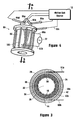
- Fig. 4 An alternate embodiment for the ICP torch of the present invention is shown in Fig. 4 and is generally designated 80.
- the molten salt is provided as droplets 62 which contain both a volatile component and a refractory component.
- the volatile component is first vaporized to create a working gas, and the working gas breaks down the refractory component into fine droplets 64.
- the fine droplets 64 are then also vaporized.
- the primary differences between the torch 80 and the torch 10 is the fact that for the torch 80, the molten salt itself is used for maintaining relatively lower operational temperatures on the structure of the torch 80. Recall, for the torch 10 the segmented wall 38 performed this function. Additionally, for the torch 80, the molten salt itself is used to shield the inner wall 56 from unwanted depositions. For the torch 10 this function was accomplished using the cleaning (shielding) gas.
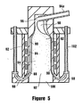
- the torch 80 includes an outer cylindrical member 82 and an inner cylindrical member 84.
- the members 82 and 84 are coaxial and, as shown, they establish a space 86 between them for an induction coil 88.
- the space 86 for torch 80 not only provides a position for the induction coil 88, it also establishes a water jacket for the induction coil 88.
- the inner member 84 establishes an inner wall 90 that effectively defines the chamber 92 of torch 80.
- the torch 80 uses a plurality of feed lines 94a-d.
- the feed lines 94 of which the feed line 94a is exemplary, will introduce the molten salt as a slurry 96 which is directed tangentially against the inner wall 90.
- V ⁇ 0.5 to 2 m/sec
- the operation of the torch 80 is initiated in a manner similar to that disclosed above for torch 10. Specifically, a noble gas, such as Argon, is used to heat the chamber 92. Once the chamber is heated, the throughput of molten salt is gradually increased until the Argon gas is no longer required. During the transit of the film of molten salt through the chamber 92, the heat that is inside the chamber 92 will cause the molten salt to boil off as droplets 62. As before, the volatile component of the droplets 62 then vaporize to break down the refractory component into fine droplets 64. The resultant fine droplets 64 of the refractory component, in turn, also vaporize. All of this occurs in the manner described above for the operation of torch 10.
- a noble gas such as Argon
Landscapes
- Physics & Mathematics (AREA)
- Engineering & Computer Science (AREA)
- Plasma & Fusion (AREA)
- Spectroscopy & Molecular Physics (AREA)
- Electromagnetism (AREA)
- Plasma Technology (AREA)
- Physical Or Chemical Processes And Apparatus (AREA)
- Vaporization, Distillation, Condensation, Sublimation, And Cold Traps (AREA)
Applications Claiming Priority (2)
| Application Number | Priority Date | Filing Date | Title |
|---|---|---|---|
| US480097 | 1990-02-14 | ||
| US09/480,097 US6410880B1 (en) | 2000-01-10 | 2000-01-10 | Induction plasma torch liquid waste injector |
Publications (2)
| Publication Number | Publication Date |
|---|---|
| EP1117280A2 true EP1117280A2 (de) | 2001-07-18 |
| EP1117280A3 EP1117280A3 (de) | 2003-05-14 |
Family
ID=23906664
Family Applications (1)
| Application Number | Title | Priority Date | Filing Date |
|---|---|---|---|
| EP00310685A Withdrawn EP1117280A3 (de) | 2000-01-10 | 2000-12-01 | Injektor von flüssigen Abfällen in einem induktiv-gekoppelten Plasmabrenner |
Country Status (3)
| Country | Link |
|---|---|
| US (1) | US6410880B1 (de) |
| EP (1) | EP1117280A3 (de) |
| JP (1) | JP3603028B2 (de) |
Cited By (1)
| Publication number | Priority date | Publication date | Assignee | Title |
|---|---|---|---|---|
| EP1367441B1 (de) * | 2002-05-28 | 2013-08-28 | University of Central Florida Foundation, Inc. | Gasdynamisch-kontrollierte Tröpfchen als Target für eine Laser-Plasma Strahlungsquelle im extrem-ultravioletten Bereich |
Families Citing this family (26)
| Publication number | Priority date | Publication date | Assignee | Title |
|---|---|---|---|---|
| US6579805B1 (en) * | 1999-01-05 | 2003-06-17 | Ronal Systems Corp. | In situ chemical generator and method |
| US7857972B2 (en) | 2003-09-05 | 2010-12-28 | Foret Plasma Labs, Llc | Apparatus for treating liquids with wave energy from an electrical arc |
| US7622693B2 (en) | 2001-07-16 | 2009-11-24 | Foret Plasma Labs, Llc | Plasma whirl reactor apparatus and methods of use |
| US8764978B2 (en) | 2001-07-16 | 2014-07-01 | Foret Plasma Labs, Llc | System for treating a substance with wave energy from an electrical arc and a second source |
| US8981250B2 (en) * | 2001-07-16 | 2015-03-17 | Foret Plasma Labs, Llc | Apparatus for treating a substance with wave energy from plasma and an electrical Arc |
| US10188119B2 (en) | 2001-07-16 | 2019-01-29 | Foret Plasma Labs, Llc | Method for treating a substance with wave energy from plasma and an electrical arc |
| US6787044B1 (en) | 2003-03-10 | 2004-09-07 | Archimedes Technology Group, Inc. | High frequency wave heated plasma mass filter |
| US7375035B2 (en) * | 2003-04-29 | 2008-05-20 | Ronal Systems Corporation | Host and ancillary tool interface methodology for distributed processing |
| US7429714B2 (en) * | 2003-06-20 | 2008-09-30 | Ronal Systems Corporation | Modular ICP torch assembly |
| US20050172896A1 (en) * | 2004-02-10 | 2005-08-11 | Tihiro Ohkawa | Injector for plasma mass filter |
| US20050194099A1 (en) * | 2004-03-03 | 2005-09-08 | Jewett Russell F.Jr. | Inductively coupled plasma source using induced eddy currents |
| US8357242B2 (en) | 2007-05-03 | 2013-01-22 | Jewett Russell F | Crystalline film devices, apparatuses for and methods of fabrication |
| US20060233968A1 (en) * | 2005-04-19 | 2006-10-19 | Tihiro Ohkawa | System and method for vaporizing a metal |
| US20070092050A1 (en) * | 2005-10-21 | 2007-04-26 | Parks Paul B | Microwave-powered pellet accelerator |
| US7831008B2 (en) * | 2005-10-21 | 2010-11-09 | General Atomics | Microwave-powered pellet accelerator |
| CA2683165C (en) | 2006-04-05 | 2013-06-11 | Foret Plasma Labs, Llc | System, method and apparatus for treating liquids with wave energy from plasma |
| US8199790B2 (en) * | 2007-11-02 | 2012-06-12 | Plasma Waste Recycling, Inc. | Reactor vessel for plasma gasification |
| US9174296B2 (en) * | 2010-10-20 | 2015-11-03 | Lam Research Corporation | Plasma ignition and sustaining methods and apparatuses |
| CN104520453A (zh) | 2011-11-10 | 2015-04-15 | 先进磁工艺股份有限公司 | 用于分离的磁电-等离子体分离器及方法 |
| US9279722B2 (en) | 2012-04-30 | 2016-03-08 | Agilent Technologies, Inc. | Optical emission system including dichroic beam combiner |
| US9499443B2 (en) | 2012-12-11 | 2016-11-22 | Foret Plasma Labs, Llc | Apparatus and method for sintering proppants |
| CN105189919B (zh) | 2013-03-12 | 2017-12-01 | 弗雷特等离子实验室公司 | 用于烧结支撑剂的设备和方法 |
| US9717139B1 (en) * | 2013-08-26 | 2017-07-25 | Elemental Scientific, Inc. | Torch cooling device |
| US10847277B2 (en) | 2016-09-30 | 2020-11-24 | Plasmanano Corporation | Apparatus for reducing radioactive nuclear waste and toxic waste volume |
| CN112709997B (zh) * | 2021-02-01 | 2024-09-24 | 山东欧卡环保工程有限公司 | 一种等离子连续裂解和玻璃化处理废液设备及处理方法 |
| CN112709996B (zh) * | 2021-03-09 | 2024-09-24 | 山东欧卡环保工程有限公司 | 一种处理废液的等离子焚烧裂解炉 |
Family Cites Families (8)
| Publication number | Priority date | Publication date | Assignee | Title |
|---|---|---|---|---|
| SE338962B (de) | 1970-06-04 | 1971-09-27 | B Lehnert | |
| US4431901A (en) | 1982-07-02 | 1984-02-14 | The United States Of America As Represented By The United States Department Of Energy | Induction plasma tube |
| US4897579A (en) * | 1987-04-13 | 1990-01-30 | The United States Of America As Represented By The United States Department Of Energy | Method of processing materials using an inductively coupled plasma |
| US5070228A (en) * | 1990-06-18 | 1991-12-03 | General Electric Company | Method for plasma spray joining active metal substrates |
| US5560844A (en) | 1994-05-26 | 1996-10-01 | Universite De Sherbrooke | Liquid film stabilized induction plasma torch |
| US5611947A (en) | 1994-09-07 | 1997-03-18 | Alliant Techsystems, Inc. | Induction steam plasma torch for generating a steam plasma for treating a feed slurry |
| GB9704077D0 (en) | 1996-03-15 | 1997-04-16 | British Nuclear Fuels Plc | Improvements in and relating to processing |
| US5877471A (en) * | 1997-06-11 | 1999-03-02 | The Regents Of The University Of California | Plasma torch having a cooled shield assembly |
-
2000
- 2000-01-10 US US09/480,097 patent/US6410880B1/en not_active Expired - Fee Related
- 2000-12-01 EP EP00310685A patent/EP1117280A3/de not_active Withdrawn
-
2001
- 2001-01-09 JP JP2001000929A patent/JP3603028B2/ja not_active Expired - Fee Related
Cited By (1)
| Publication number | Priority date | Publication date | Assignee | Title |
|---|---|---|---|---|
| EP1367441B1 (de) * | 2002-05-28 | 2013-08-28 | University of Central Florida Foundation, Inc. | Gasdynamisch-kontrollierte Tröpfchen als Target für eine Laser-Plasma Strahlungsquelle im extrem-ultravioletten Bereich |
Also Published As
| Publication number | Publication date |
|---|---|
| JP2001252554A (ja) | 2001-09-18 |
| JP3603028B2 (ja) | 2004-12-15 |
| US6410880B1 (en) | 2002-06-25 |
| EP1117280A3 (de) | 2003-05-14 |
Similar Documents
| Publication | Publication Date | Title |
|---|---|---|
| US6410880B1 (en) | Induction plasma torch liquid waste injector | |
| US9932673B2 (en) | Microwave plasma apparatus and method for materials processing | |
| US20240043142A1 (en) | Sources for plasma assisted electric propulsion | |
| US5144110A (en) | Plasma spray gun and method of use | |
| KR100776068B1 (ko) | 트윈 플라즈마 토치 장치 | |
| EP0368547B1 (de) | Verfahren und Vorrichtung zur Erzeugung von Plasma | |
| US5560844A (en) | Liquid film stabilized induction plasma torch | |
| JP4082905B2 (ja) | プラズマ被膜表面仕上げの方法及び装置 | |
| RU2569861C2 (ru) | Система термического плазменно-дугового проволочного напыления | |
| US20050223992A1 (en) | Miniature microwave plasma torch application and method of use thereof | |
| US5630880A (en) | Method and apparatus for a large volume plasma processor that can utilize any feedstock material | |
| JPH0450070B2 (de) | ||
| KR200493866Y1 (ko) | 열 플라즈마 토치 | |
| US6943316B2 (en) | Arrangement for generating an active gas jet | |
| KR102106179B1 (ko) | 현탁액 플라즈마 용사 공정을 위한 반응성 기체 보호대 또는 화염 피복 | |
| US10730239B1 (en) | 3D printing apparatus using a beam of an atmospheric pressure inductively coupled plasma generator | |
| US8028654B2 (en) | Planar controlled zone microwave plasma system | |
| US5159173A (en) | Apparatus for reducing plasma constriction by intermediate injection of hydrogen in RF plasma gun | |
| US5095189A (en) | Method for reducing plasma constriction by intermediate injection of hydrogen in RF plasma gun | |
| US5743961A (en) | Thermal spray coating apparatus | |
| JP7503345B2 (ja) | コーティング用粉体エアロゾル蒸着用マイクロ波プラズマノズル、及びこれを利用するコーティング用粉体エアロゾルによるコーティング装置 | |
| KR102625384B1 (ko) | 플라즈마 토치 및 이를 이용하여 대상기체를 처리하는 방법 | |
| Ripley et al. | Controlled zone microwave plasma system | |
| Schram et al. | Method of treating surfaces of substrates with the aid of a plasma and a reactor for carrying out the method |
Legal Events
| Date | Code | Title | Description |
|---|---|---|---|
| PUAI | Public reference made under article 153(3) epc to a published international application that has entered the european phase |
Free format text: ORIGINAL CODE: 0009012 |
|
| AK | Designated contracting states |
Kind code of ref document: A2 Designated state(s): AT BE CH CY DE DK ES FI FR GB GR IE IT LI LU MC NL PT SE TR |
|
| AX | Request for extension of the european patent |
Free format text: AL;LT;LV;MK;RO;SI |
|
| PUAL | Search report despatched |
Free format text: ORIGINAL CODE: 0009013 |
|
| AK | Designated contracting states |
Designated state(s): AT BE CH CY DE DK ES FI FR GB GR IE IT LI LU MC NL PT SE TR |
|
| AX | Request for extension of the european patent |
Extension state: AL LT LV MK RO SI |
|
| RIC1 | Information provided on ipc code assigned before grant |
Ipc: 7H 05H 1/30 B Ipc: 7H 05H 1/42 A |
|
| 17P | Request for examination filed |
Effective date: 20030718 |
|
| AKX | Designation fees paid |
Designated state(s): DE FR GB |
|
| RAP1 | Party data changed (applicant data changed or rights of an application transferred) |
Owner name: ARCHIMEDES OPERATING, LLC |
|
| STAA | Information on the status of an ep patent application or granted ep patent |
Free format text: STATUS: THE APPLICATION HAS BEEN WITHDRAWN |
|
| 18W | Application withdrawn |
Effective date: 20060503 |