EP1117460B1 - Catheter de melange de composants - Google Patents
Catheter de melange de composants Download PDFInfo
- Publication number
- EP1117460B1 EP1117460B1 EP99950119A EP99950119A EP1117460B1 EP 1117460 B1 EP1117460 B1 EP 1117460B1 EP 99950119 A EP99950119 A EP 99950119A EP 99950119 A EP99950119 A EP 99950119A EP 1117460 B1 EP1117460 B1 EP 1117460B1
- Authority
- EP
- European Patent Office
- Prior art keywords
- catheter
- applicator
- sealant
- respect
- component
- Prior art date
- Legal status (The legal status is an assumption and is not a legal conclusion. Google has not performed a legal analysis and makes no representation as to the accuracy of the status listed.)
- Expired - Lifetime
Links
- 239000000565 sealant Substances 0.000 claims abstract description 84
- 230000009977 dual effect Effects 0.000 claims abstract description 11
- 239000012858 resilient material Substances 0.000 claims abstract description 3
- 230000007246 mechanism Effects 0.000 claims description 22
- 239000003795 chemical substances by application Substances 0.000 claims description 12
- 239000012530 fluid Substances 0.000 claims description 9
- 239000000463 material Substances 0.000 claims description 8
- 239000007788 liquid Substances 0.000 claims description 3
- 239000003381 stabilizer Substances 0.000 claims 3
- 239000011343 solid material Substances 0.000 claims 1
- 108010049003 Fibrinogen Proteins 0.000 abstract description 12
- 102000008946 Fibrinogen Human genes 0.000 abstract description 12
- 229940012952 fibrinogen Drugs 0.000 abstract description 12
- 108090000190 Thrombin Proteins 0.000 abstract description 6
- 229960004072 thrombin Drugs 0.000 abstract description 6
- 230000000451 tissue damage Effects 0.000 abstract 1
- 231100000827 tissue damage Toxicity 0.000 abstract 1
- 230000000087 stabilizing effect Effects 0.000 description 11
- 238000000034 method Methods 0.000 description 8
- 210000001519 tissue Anatomy 0.000 description 5
- 239000012190 activator Substances 0.000 description 3
- 230000015271 coagulation Effects 0.000 description 3
- 238000005345 coagulation Methods 0.000 description 3
- 238000010276 construction Methods 0.000 description 3
- 230000000994 depressogenic effect Effects 0.000 description 3
- 230000000694 effects Effects 0.000 description 3
- 239000000203 mixture Substances 0.000 description 3
- 238000007906 compression Methods 0.000 description 2
- 230000006835 compression Effects 0.000 description 2
- 210000003811 finger Anatomy 0.000 description 2
- -1 for example Substances 0.000 description 2
- 230000004048 modification Effects 0.000 description 2
- 238000012986 modification Methods 0.000 description 2
- 230000037361 pathway Effects 0.000 description 2
- 239000007787 solid Substances 0.000 description 2
- 238000007711 solidification Methods 0.000 description 2
- 230000008023 solidification Effects 0.000 description 2
- 239000000126 substance Substances 0.000 description 2
- 238000001356 surgical procedure Methods 0.000 description 2
- BHPQYMZQTOCNFJ-UHFFFAOYSA-N Calcium cation Chemical compound [Ca+2] BHPQYMZQTOCNFJ-UHFFFAOYSA-N 0.000 description 1
- 241001631457 Cannula Species 0.000 description 1
- 108010071289 Factor XIII Proteins 0.000 description 1
- 102000009123 Fibrin Human genes 0.000 description 1
- 108010073385 Fibrin Proteins 0.000 description 1
- BWGVNKXGVNDBDI-UHFFFAOYSA-N Fibrin monomer Chemical compound CNC(=O)CNC(=O)CN BWGVNKXGVNDBDI-UHFFFAOYSA-N 0.000 description 1
- 239000004743 Polypropylene Substances 0.000 description 1
- 230000002745 absorbent Effects 0.000 description 1
- 239000002250 absorbent Substances 0.000 description 1
- 230000009471 action Effects 0.000 description 1
- 230000004913 activation Effects 0.000 description 1
- 239000012620 biological material Substances 0.000 description 1
- 230000005540 biological transmission Effects 0.000 description 1
- 230000023555 blood coagulation Effects 0.000 description 1
- 229910001424 calcium ion Inorganic materials 0.000 description 1
- 239000003054 catalyst Substances 0.000 description 1
- 230000001112 coagulating effect Effects 0.000 description 1
- 238000007599 discharging Methods 0.000 description 1
- 238000013156 embolectomy Methods 0.000 description 1
- 230000003073 embolic effect Effects 0.000 description 1
- 229920006335 epoxy glue Polymers 0.000 description 1
- 229940012444 factor xiii Drugs 0.000 description 1
- 229950003499 fibrin Drugs 0.000 description 1
- 238000009472 formulation Methods 0.000 description 1
- 230000023597 hemostasis Effects 0.000 description 1
- 230000008105 immune reaction Effects 0.000 description 1
- 230000006698 induction Effects 0.000 description 1
- 208000015181 infectious disease Diseases 0.000 description 1
- 210000002381 plasma Anatomy 0.000 description 1
- 230000000379 polymerizing effect Effects 0.000 description 1
- 229920001155 polypropylene Polymers 0.000 description 1
- 238000002360 preparation method Methods 0.000 description 1
- 238000010926 purge Methods 0.000 description 1
- 229920002379 silicone rubber Polymers 0.000 description 1
- 239000004945 silicone rubber Substances 0.000 description 1
- 239000007779 soft material Substances 0.000 description 1
- 238000009987 spinning Methods 0.000 description 1
- 229910001220 stainless steel Inorganic materials 0.000 description 1
- 239000010935 stainless steel Substances 0.000 description 1
- 230000001225 therapeutic effect Effects 0.000 description 1
- 210000003813 thumb Anatomy 0.000 description 1
- 239000003106 tissue adhesive Substances 0.000 description 1
- 230000029663 wound healing Effects 0.000 description 1
Images






Classifications
-
- A—HUMAN NECESSITIES
- A61—MEDICAL OR VETERINARY SCIENCE; HYGIENE
- A61M—DEVICES FOR INTRODUCING MEDIA INTO, OR ONTO, THE BODY; DEVICES FOR TRANSDUCING BODY MEDIA OR FOR TAKING MEDIA FROM THE BODY; DEVICES FOR PRODUCING OR ENDING SLEEP OR STUPOR
- A61M37/00—Other apparatus for introducing media into the body; Percutany, i.e. introducing medicines into the body by diffusion through the skin
-
- A—HUMAN NECESSITIES
- A61—MEDICAL OR VETERINARY SCIENCE; HYGIENE
- A61M—DEVICES FOR INTRODUCING MEDIA INTO, OR ONTO, THE BODY; DEVICES FOR TRANSDUCING BODY MEDIA OR FOR TAKING MEDIA FROM THE BODY; DEVICES FOR PRODUCING OR ENDING SLEEP OR STUPOR
- A61M2202/00—Special media to be introduced, removed or treated
- A61M2202/04—Liquids
- A61M2202/0413—Blood
- A61M2202/0415—Plasma
- A61M2202/0425—Thrombin
-
- A—HUMAN NECESSITIES
- A61—MEDICAL OR VETERINARY SCIENCE; HYGIENE
- A61M—DEVICES FOR INTRODUCING MEDIA INTO, OR ONTO, THE BODY; DEVICES FOR TRANSDUCING BODY MEDIA OR FOR TAKING MEDIA FROM THE BODY; DEVICES FOR PRODUCING OR ENDING SLEEP OR STUPOR
- A61M2202/00—Special media to be introduced, removed or treated
- A61M2202/04—Liquids
- A61M2202/0413—Blood
- A61M2202/0445—Proteins
- A61M2202/0447—Glycoproteins
- A61M2202/0449—Fibrinogen, also called factor 1
Definitions
- the present invention relates to an apparatus for applying component parts of a sealant which when mixed transforms from a fluidic state to a non-fluidic state.
- the present invention is directed to an apparatus in which sealant components are mixed prior to being applied to biological tissue to effect hemostasis or achieve other therapeutic results.
- tissue sealants and other biological materials are an important emerging surgical technique, well adapted for the operating room or field environments such as the doctor's office or mobile medical units.
- application of such sealants via a catheter provides a non evasive medical technique.
- Preferred sealants include fibrin sealants which are formed from blood plasma components and comprise, on the one hand, a first component containing fibrinogen and Factor XIII and on the other hand a second component which usually includes thrombin, and calcium ions.
- the fibrinogen is capable of a polymerizing and being cross-linked to form a solid tibrin clot when the components are mixed.
- the necessary additional factors to simulate relevant portions of the natural blood coagulation cascade are suitably distributed between the fibrinogen and thrombin components.
- a popular manually operable applicator for such two-component sealants employs a dual syringe construction wherein two syringes, connected by yoke, each provide a reservoir for one of the components.
- the sealant components are discharged in separate streams and mixed externally of the applicator.
- Such applicators are similar in principle to household epoxy glue applicators commonly available in hardware stores. Achieving effective mixing externally of the applicator is problematic.
- the possibility of retrograde clearing of the mixed fluids pathway within the applicator, using suction is also disclosed.
- the applicator is provided with suitable suction conduits and valving to apply suction to the work surface, to prepare it for the application of sealant, for example by removing fluids.
- the valving is operable to effect retrograde clearing of a sealant dispensing pathway. Enhanced mixing is possible for example, by impingement and problems of fouling by deposited solids are avoided.
- One difficulty is that the coagulating nature of the sealants causes the discharge opening or openings of an application device to become clogged so that flow out of the applicator slows down or stops.
- US-A-5,443,454 describes an embolectomy catheter containing a lumen for the introduction of a liquid substance and provided in the distal and thereof with spinning means for extruding the liquid substance in the form of a filamentous embolic material.
- the present invention solves this problem by providing a sealant applicator comprising a dual catheter communicating with fluid sealant agent sources, for example, two internal reservoirs, which sealant applicator can effectively deliver multiple sealant components to a remote tip of the catheter for mixing and dispensing to an area of application.
- This catheter is a dual catheter having one catheter movably mounted with respect to another, for example longitudinally within the other. The movable catheter is then used as a plunger to unclog the openings.
- the present invention enables an effective sealant composition to reach an area of application by mixing the sealant components to application or contact with the work surface and providing for removal of coagulated sealant.
- the sealant is a biological sealant, for example a tissue adhesive, and the area of application is a biological tissue subject to surgery.
- the sealant components can comprise a first, structural component capable of gelling, and preferably of solidification and a second, activation component which activates such gelling and, optionally, solidification. More preferably, the sealant is a tissue sealant and the first component comprises fibrinogen and the second component comprises, or can generate a fibrinogen activator, especially thrombin or an equivalent thereof.
- Applicator tO comprises a pair of inner and outer coaxial catheters 12 and 14.
- inner and outer catheters 12 and 14 are elongated tubes.
- Inner and outer catheters 12 and 14 are constructed out of any suitable, preferably sterilizable material, for example, stainless steel or polypropylene, and may be rigid or flexible, or may comprise both rigid and flexible components along their lengths.
- catheters are substantially longer than the dispensing cannulas described in preferred embodiments of the parent application, having, for example, a length of at least 10 cm, often at least 20 cm and sometimes being substantially longer, for example a meter or more.
- catheters are flexible, or have a flexible portion.
- Inner catheter 14 defines an area 16 and is of a smaller diameter than outer catheter 12, this allows outer catheter 12 to surround inner catheter 14 leaving a second area 18.
- Outer catheter 12 is configured to have an opening 20 for dispersing a mixed sealant 22.
- Sealant 22 is typically comprised of a first sealant agent or component 24 and a second agent or component 26.
- Component 24 is contained within area 16 and component 26 is contained with area 18.
- Inner catheter 14 has an opening 28 for discharge of component 24, and in the position shown in Figure 1 is retracted behind opening 20 of outer catheter 12 to provide a mixing volume 29.
- areas 16 and 18 and their respective ratios are of such a configuration as to provide desired proportions of components 24 and 26 to provide a sealant 22 in accordance with the required parameters.
- areas 16 and 18 and their corresponding volumes may be varied to provide a sealant 22 of various characteristics. For instance, a sealant that may require a longer time to cure or a sealant that may require lesser time to cure by using a lesser or greater proportion or concentration of activator, e.g. thrombin for a fibrinogen sealant.
- Areas 16 and 18 are of sufficient size to allow for unimpeded flow of the sealant components.
- Inner catheter 14 is slidably or otherwise movably mounted with respect to outer catheter 12 to permit relative movement of inner catheter 14 in the directions of arrow 30.
- outer catheter 12 allows opening 28 of inner catheter 14 to be positioned within outer catheter 12 and away from opening 20. This position allows components 24 and 26 to mix in an area in close proximity to opening 20. Moreover, and as illustrated in Figure 3a, the position of opening 28 may be further retracted with respect to outer catheter 12. This positioning will provide a larger mixing volume 29 allowing for a longer mixing time of component 24 and 26.
- opening 28 may be positioned closer to opening 20, if desired, to reduce the volume of mixing volume 29 and the time components 24 and 26 are in contact with each other inside applicator 10. This may be appropriate for a very fast setting sealant.
- a stabilizing ring 27 (as illustrated by the dashed lines in Figure 3a) or the equivalent thereof can be affixed to inner catheter 14 and extend outwardly to outer catheter 12. Stabilizing ring 27 provides stability to inner catheter 14 and is configured to allow component 26 to flow through the same.
- a plurality of stabilizing rings 27 may positioned within applicator 10 to provide stability to inner catheter 14.
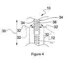
- the movement of inner catheter 14 may be effected by any suitable mechanism for example, a proximally located ratchet and pawl mechanism as illustrated in Figure 4.
- a locking mechanism 32 restricts the movement of the proximal end of inner catheter 14 by engaging with a plurality of nubs 34. Movement of mechanism 32 into a position, as illustrated by the dashed lines in Figure 4 will once more allow inner catheter 14 to move in the direction of arrow 30.
- Mechanism 32 may be configured to have a conveniently placed trigger to facilitate the release.
- mechanism 32 can work in conjunction with a return spring 35 which is depressed as inner catheter 14 is depressed. Accordingly, as mechanism 32 is released the force of spring 35 acts to return inner catheter 14 to its original position.
- inner catheter 14 may be provided with graduated markings 36.
- Markings 36 can indicate the relative position of opening 28 of inner catheter 14 with respect to opening 20 of outer catheter 12. For instance, a marking of zero would indicate that opening 28 and opening 20 are flush with each other. Other markings such as +1, +2, +3, or - 1, -2, -3 would indicate the respective location of opening 28 with respect to 20.
- markings 36 can indicate the flow output of sealant 22 depending on the position of opening 28.
- markings 36 can be configured to indicate flow output of mixed sealant 22, such as millimeters per second or any other suitable indicator of flow output.
- markings 36 may also be configured to refer to the mixture ratio of component 24 with respect to component 26.
- inner catheter 14 with respect to outer catheter 12 also allows a user to conveniently purge any clot of hardened sealant 22 from opening 20, as will now be further explained.
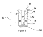
- stabilizing ring 27 ( Figures 3a and 3b) is also used as a plunger for removal of clot 38.
- stabilizing ring 27 is slidably mounted in area 18 positioned between inner catheter 14 and outer catheter 12. Movement of ring 27 is effected through the use of a user manipulated trigger mechanism. To remove clot 38 the user simply causes ring 27 to move towards opening 20. Such movement will dislodge clot 38.
- a plurality of stabilizing rings 27 may be positioned throughout area 18.
- Stabilizing ring 27 allows component 26 to flow through area 18 unimpeded, however, stabilizing ring 27 is constructed in such a manner as to force clot 38 from opening 20 once stabilizing ring 27 has made contact with clot 38.
- One such configuration is that of a spoked wheel (Figure 3b) wherein the spokes 33 of stabilizing ring or rings 27 define a plurality of openings 35. Openings 35 are large enough to allow component 26 to pass through while being small enough to force the removal of clot 38.
- ring or rings 27 is a disk having a plurality of smaller openings 35 ( Figure 3c).
- Movement of stabilizing ring 27 is effected through the use of a trigger mechanism, such as a plunger or the equivalent thereof, positioned at the proximal end of applicator 10 which is conveniently accessed by the user's finger or thumb.
- a trigger mechanism such as a plunger or the equivalent thereof
- ring or rings 27 are secured to inner catheter 14. Thus, as the user manipulates or moves inner catheter 14 ring 27 also moves.
- rings 27, or inner catheter 14 with rings 27 secured to it are capable of being rotated as they are being depressed. Such rotation will enhance the dislodging of clot 38.
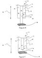
- FIG. 7 a user first moves inner catheter 14 into the position illustrated in Figure 7. The movement will dislodge clot 38 from opening 28 of inner catheter 14. Then the user moves inner catheter 14 into the position illustrated in Figure 8. This movement allows inner catheter 14 to act as a plunger which will dislodge clot 38 from opening 20 thereby discharging clot 38 from applicator 10.
- catheters 12 and 14 may be constructed out of a flexible material capable of being manipulated into the squeezed position illustrated by the dashed lines. This configuration allows the distal end of applicator 10 to be compressed to dislodge clot 38. In addition, small amounts of components 24 and 26 will be forcibly dispelled during this compression and will aid in the clearing of applicator 10.
- the manipulation of applicator 10 can be performed by the fingers of the user or a pinching mechanism which could be hand held or adhered to applicator 10.
- catheters 12 and 14 may be constructed out of a flexible material capable of be manipulated at the proximal end of applicator 10 to effectively pinch off the supply of components 26 and 24.
- the compression of catheters 12 and 14 at the proximal end also causes small amounts of components 24 and 26 to be discharged.
- Such placement of a pinching mechanism or pinching capability at the proximal end of applicator 10 also provides for an ergonomic device.
- Openings 28 and 20 may be equipped with a closing mechanism, such as removable cover 31 (illustrated in Figure 9) which prevents unrestricted flow of components 24 and 26 from inner and outer catheters 12 and 14 between uses.
- a closing mechanism such as removable cover 31 (illustrated in Figure 9) which prevents unrestricted flow of components 24 and 26 from inner and outer catheters 12 and 14 between uses.
- FIG. 10 and 10a an alternative embodiment of the present invention is illustrated.
- components and/or parts performing analogous or similar functions are numbered in multiples of 100.
- an opening or plurality of openings 128 are positioned along the elongated portions or walls of catheter 114. These openings allow component 124 to mix with component 126 throughout an extended mixing volume 129 prior to discharge of mixed sealant 122 from opening 120.
- This embodiment allows for a particularly effective mixing of components 124 and 126 prior to application.
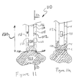
- catheter 114 In this embodiment the end of catheter 114 is closed. Accordingly, mixed sealant 122 is applied to the required location through opening 120. Catheter 114 may also be positioned to apply sealant 122 as illustrated in Figures 11 and 11a.
- catheter 114 may also be used as a plunger to remove clot 138 (as illustrated by the dashed lines in Figure 11a).
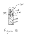
- catheter 214 is configured to have a plurality of smaller openings 228 throughout a selected length of the distal end of the catheter 214, for example 1 or 2 cm., or the entire surface of catheter 214.
- This configuration allows for an even greater mixing volume 229.
- sufficient pressure of sealant agent or component is maintained in inner catheter 214 to ensure avoid possible backflow and clogging of openings 228 owing to mixing of the sealant components in the openings.
- small amounts of components 24 and 26 may also be expelled with the clot to ensure that all of the clot is removed from applicator 10.
- a flexible connector 14a is connected to the proximal end of inner catheter 14.
- Flexible connector 14a supplies area 16 with sealant component 24.
- the flexible nature of connector 14a allows inner catheter 14 to move in the directions of arrow 30.
- Movement of inner catheter 14 is facilitated by the manipulation of an actuating mechanism 40 which is secured to inner catheter 14 via a clamping device 42.
- Such manipulation causes a corresponding movement of inner catheter 14, and may be effected by a manual control (not shown), for example a spring-loaded depressible button or trigger.
- a flexible gasket 44 allows for movement of inner catheter 14 while providing a secure seal around catheters 14 and 12.
- Outer catheter 12 is also connected to a connector 12a.
- Connector 12a supplies area 18 with sealant component 26.
- Connector 12a may also be flexible, however connector 12a may be constructed out of a more rigid material.
- catheter 312 is configured to have a flexible and expansible portion 346, which can, for example, be of fanfold or accordion-like bellows construction and is located intermediate to catheter 312 and connector 312a.
- Flexible portion 346 allows for constriction and expansion of outer catheter 312 in the directions depicted by arrow 330. Movement of catheter 312 is effectuated by an actuating mechanism 340. As mechanism 340 advances or retracts catheter 312 also moves in the same direction.
- catheter 12 is configured to have a tapered end, constricting the flow of sealant components to provide a mixing volume 29 with strong turbulence.
- the outer diameter of inner catheter 14 can be as large as opening 20, thus when inner catheter 14 is advanced, it exerts a precise plug-removal clearing action on the reduced diameter tip of outer catheter 12.
- the embodiment of the invention shown in Figures 16-17 comprises a modified clearing-enabled, dual catheter sealant applicator 360 which can be fabricated from suitably soft or resilient materials, to have a flexible or malleable end or tip 362 to facilitate or enhance engagement of the applicator with, and entry of the applicator into, living tissues, for example, the ear, the nose or the throat.
- the material of applicator 360, at least at tip 362, should preferably be sterilizable and non-absorbent, as well as soft, or deformable, and resilient, and may for example, be a silicone rubber.
- Catheter sealant applicator 360 comprises a hollow outer sheath 364, an inner plug 366 which has an axial bore 368 and external channels 370, and a supply lumen 372 press-fitted into plug 366. As shown, four symmetrically disposed channels 370 are provided, but other numbers of channels 370 such as three, six or eight may be employed.
- the outer diameter of plug 366 is a close sliding fit within the inner diameter of sheath 364.
- the cross-sectional areas of channels 370 and bore 368 are selected to provide desired relative flow rates of sealant agents, which relative flow rates may be varied, or selected, by using plugs 366 of different configurations.
- Such diverse plugs 366 may be supplied each with a lumen 372, or may be interchangeably fittable to one or more lumens 372.
- channels 370 on plug 366 can taper outwardly, in the fluid delivery direction, which is to say distally, to increase the channel area in the direction of flow and facilitate clearing and the removal of clots.
- channels 370 have a helical configuration, as shown, simulating rifling, to impart spin to the fluid travel to enhance mixing of the sealant agents.
- a still further option is for channels 370 to be twisted in opposed directions around plug 366, to impart countercurrent flows and further enhance mixing.
- the sealant catalyst for example, in the case of a fibrinogen sealant, thrombin or other fibrinogen activator, is supplied through lumen 372 to bore 368 in plug 366, and fibrinogen or other polymerizable sealant agent, is supplied in the space between the outside of the lumen and the inside diameter 374 of sheath 364.
- the forward or distal face of plug 366 is slightly retracted behind the distal end of sheath 364 to allow mixing of the two agents to take place in a mixing volume disposed generally within the sheath 364.
- significant mixing of the sealant components takes place before delivery of the sealant agents to, or contact of the sealant agents with, the target work surface.
- tip 362 can be cleared of any clot or other material, by advancing lumen 372, driving plug 366 forwardly inside sheath 364 and expelling the clot. If necessary, the clot can be freed from the face of plug 366, or loosened, by dispensing a small amount of sealant.
Landscapes
- Health & Medical Sciences (AREA)
- Engineering & Computer Science (AREA)
- Dermatology (AREA)
- Medical Informatics (AREA)
- Anesthesiology (AREA)
- Biomedical Technology (AREA)
- Heart & Thoracic Surgery (AREA)
- Hematology (AREA)
- Life Sciences & Earth Sciences (AREA)
- Animal Behavior & Ethology (AREA)
- General Health & Medical Sciences (AREA)
- Public Health (AREA)
- Veterinary Medicine (AREA)
- Materials For Medical Uses (AREA)
- Surgical Instruments (AREA)
- Infusion, Injection, And Reservoir Apparatuses (AREA)
- Media Introduction/Drainage Providing Device (AREA)
Claims (25)
- Applicateur de produit d'obturation à composants multiples (10), comprenant un cathéter double pour la distribution du produit d'obturation qui comporte un premier cathéter, un deuxième cathéter et qui définit en outre un volume de mélange (29) à l'intérieur du cathéter double pour mélanger les composants multiples (24, 26) du produit d'obturation avant la sortie de celui-ci à une extrémité distale du cathéter, dans lequel les premier et deuxième cathéters communiquent chacun avec une de deux sources de composant fluide du produit d'obturation, caractérisé en que le premier cathéter est configuré pour être monté de façon mobile par rapport au deuxième cathéter.
- Applicateur (10) selon la revendication 1, dans lequel un premier cathéter est monté pour un mouvement longitudinal dans l'autre cathéter.
- Applicateur (10) selon la revendication 1, comprenant en outre un système de nettoyage pour chasser une matière indésirable du volume de mélange (29) ou du voisinage du volume de mélange.
- Applicateur (10) selon une quelconque des revendications 1 à 3, dans lequel chaque cathéter communique avec une de deux sources de composant fluide de produit d'obturation et dans lequel un cathéter est monté pour un mouvement longitudinal dans l'autre cathéter, et le cathéter intérieur (14) est utilisable comme plongeur pour chasser les bouchages.
- Applicateur (10) selon la revendication 1, comprenant un élément de stabilisation pour positionner un cathéter par rapport à l'autre.
- Applicateur (10) selon la revendication 2, comprenant en outre un élément de stabilisation pour positionner un cathéter par rapport à l'autre, dans lequel l'élément de stabilisation comprend un anneau (27) disposé dans le cathéter extérieur (12) autour du cathéter intérieur (14) et comportant des trous (35) pour le passage du composant de produit d'obturation (26).
- Applicateur (10) selon une des revendications 1 à 3, comprenant en outre un mécanisme d'entraínement bidirectionnel couplé de façon proximale au cathéter double afin de déplacer un cathéter longitudinalement dans les deux sens par rapport à l'autre.
- Applicateur (10) selon la revendication 7, dans lequel le mécanisme d'entraínement comprend un encliquetage.
- Applicateur (10) selon une quelconque des revendications 1 à 3, comprenant en outre une échelle graduée (36) pour indiquer la position relative d'un cathéter par rapport à l'autre.
- Applicateur (10) selon la revendication 6, comprenant en outre un mécanisme de nettoyage de caillot qui agit pour amener l'anneau de stabilisation (27) en contact avec un caillot (38) à éliminer.
- Applicateur (10) selon la revendication 10, dans lequel le mécanisme de nettoyage de caillot comprend une gâchette actionnable à la main.
- Applicateur (10) selon la revendication 1, dans lequel les cathéters ont des extrémités distales élastiquement déformables pour chasser les caillots (38).
- Applicateur (10) selon la revendication 1, comprenant en outre un couvercle (31) pour fermer l'extrémité distale du cathéter double.
- Applicateur (10) selon la revendication 2, dans lequel le cathéter intérieur (14) comprend des trous latéraux multiples (128) au voisinage de son extrémité distale, pour l'écoulement d'un composant de produit d'obturation, afin de créer un volume de mélange (129) dans l'extrémité extérieure.
- Applicateur (10) selon la revendication 14, dans lequel l'extrémité du cathéter intérieur (14) est fermée.
- Applicateur (10) selon une quelconque des revendications 1 à 3, dans lequel les extrémités proximales des cathéters sont raccordées à des sources de composants de produit d'obturation, un cathéter ayant une partie flexible qui permet de le déplacer longitudinalement par rapport à l'autre cathéter.
- Applicateur (10) selon la revendication 16, dans lequel le premier cathéter est disposé dans l'autre cathéter et entouré par celui-ci pour un mouvement à l'intérieur de l'autre cathéter, et il est relié à l'autre cathéter par un joint d'étanchéité flexible (44) permettant un mouvement relatif des cathéters et créant une étanchéité aux fluides.
- Applicateur (10) selon une quelconque des revendications 1 à 3, dans lequel les extrémités proximales des cathéters sont reliées chacune à une source respective d'un composant de produit d'obturation et un premier cathéter a une partie de paroi variable qui peut être augmentée et raccourcie longitudinalement pour permettre de faire varier la longueur de ce cathéter alternativement par rapport à l'autre cathéter, de sorte que l'extrémité distale du premier cathéter est déplacée longitudinalement en va-et-vient par rapport à l'extrémité distale de l'autre cathéter.
- Applicateur (10) selon la revendication 18, comprenant en outre un mécanisme de manoeuvre actionnable à la main (40) connecté en entraínement au premier cathéter, à un endroit situé distalement par rapport à la partie de paroi variable.
- Applicateur (10) selon une quelconque des revendications 1 à 3, dans lequel le premier cathéter est disposé dans et entouré par l'autre cathéter pour un mouvement à l'intérieur de l'autre cathéter, et il a une extrémité distale qui converge dans la direction distale.
- Applicateur (10) selon la revendication 1, dans lequel;le cathéter intérieur a une extrémité en forme de bouchon à ajustement étroit dans le cathéter extérieur et comportant des trous (128) pour le passage de l'autre composant du produit d'obturation.(a) le premier cathéter est un cathéter intérieur (14) constituant un chemin d'écoulement pour la distribution d'un premier composant du produit d'obturation (24) ;(b) le deuxième cathéter est un cathéter extérieur (12) constituant un chemin d'écoulement pour la distribution d'un autre composant du produit d'obturation, le cathéter intérieur étant disposé dans le cathéter extérieur ; et
- Applicateur (10) selon la revendication 21, dans lequel l'extrémité distale du cathéter extérieur (12) comprend une matière malléable ou élastique qui évite d'endommager un tissu biologique.
- Applicateur (10) selon la revendication 22, dans lequel le cathéter intérieur (14) est déplaçable en va-et-vient par rapport au cathéter extérieur (12) pour chasser une matière solide indésirable du volume de mélange (29).
- Applicateur (10) selon une quelconque des revendications 21 à 23, dans lequel les trous (128) dans l'extrémité en forme de bouchon du cathéter intérieur (14) comprennent des canaux formés dans la surface extérieure du bouchon.
- Applicateur (10) selon la revendication 24, dans lequel les canaux s'étendent latéralement autour des cathéters de manière à engendrer un mouvement de rotation du liquide qui passe dans les canaux, pour améliorer le mélange.
Applications Claiming Priority (3)
| Application Number | Priority Date | Filing Date | Title |
|---|---|---|---|
| US10263698P | 1998-10-01 | 1998-10-01 | |
| US102636P | 1998-10-01 | ||
| PCT/US1999/022964 WO2000018469A1 (fr) | 1998-10-01 | 1999-10-01 | Catheter de melange de composants |
Publications (3)
| Publication Number | Publication Date |
|---|---|
| EP1117460A1 EP1117460A1 (fr) | 2001-07-25 |
| EP1117460A4 EP1117460A4 (fr) | 2002-08-07 |
| EP1117460B1 true EP1117460B1 (fr) | 2005-01-12 |
Family
ID=22290881
Family Applications (1)
| Application Number | Title | Priority Date | Filing Date |
|---|---|---|---|
| EP99950119A Expired - Lifetime EP1117460B1 (fr) | 1998-10-01 | 1999-10-01 | Catheter de melange de composants |
Country Status (7)
| Country | Link |
|---|---|
| EP (1) | EP1117460B1 (fr) |
| JP (1) | JP4115669B2 (fr) |
| AT (1) | ATE286762T1 (fr) |
| AU (1) | AU765831C (fr) |
| CA (1) | CA2344280C (fr) |
| DE (1) | DE69923198T2 (fr) |
| WO (1) | WO2000018469A1 (fr) |
Families Citing this family (21)
| Publication number | Priority date | Publication date | Assignee | Title |
|---|---|---|---|---|
| US6478775B1 (en) * | 2000-10-02 | 2002-11-12 | Genyx Medical Inc. | Device for delivering non-biodegradable bulking composition to a urological site |
| AUPR514201A0 (en) * | 2001-05-21 | 2001-06-14 | Ventrassist Pty Ltd | Staged implantation of ventricular assist devices |
| AU2002308409B2 (en) * | 2001-05-21 | 2005-12-01 | Thoratec Corporation | Staged implantation of ventricular assist devices |
| US6663596B2 (en) | 2001-08-13 | 2003-12-16 | Scimed Life Systems, Inc. | Delivering material to a patient |
| US6921381B2 (en) * | 2001-10-05 | 2005-07-26 | Baxter International Inc. | Laparoscopic spray device and method of use |
| US6852099B2 (en) | 2002-06-04 | 2005-02-08 | Baxter International Inc. | Device for controllably applying liquids to body surfaces |
| WO2004087007A2 (fr) | 2003-03-25 | 2004-10-14 | Biocure, Inc. | Dispositif medical de fil en hydrogel |
| US6884232B1 (en) | 2003-10-31 | 2005-04-26 | Baxter International Inc. | Laparoscopic spray device and method of use |
| US8048101B2 (en) | 2004-02-25 | 2011-11-01 | Femasys Inc. | Methods and devices for conduit occlusion |
| US8052669B2 (en) | 2004-02-25 | 2011-11-08 | Femasys Inc. | Methods and devices for delivery of compositions to conduits |
| US9238127B2 (en) | 2004-02-25 | 2016-01-19 | Femasys Inc. | Methods and devices for delivering to conduit |
| US8048086B2 (en) | 2004-02-25 | 2011-11-01 | Femasys Inc. | Methods and devices for conduit occlusion |
| US8408480B2 (en) * | 2008-04-25 | 2013-04-02 | Confluent Surgical, Inc. | Self-cleaning spray tip |
| US10070888B2 (en) | 2008-10-03 | 2018-09-11 | Femasys, Inc. | Methods and devices for sonographic imaging |
| US12171463B2 (en) | 2008-10-03 | 2024-12-24 | Femasys Inc. | Contrast agent generation and injection system for sonographic imaging |
| US9554826B2 (en) | 2008-10-03 | 2017-01-31 | Femasys, Inc. | Contrast agent injection system for sonographic imaging |
| WO2015093274A1 (fr) * | 2013-12-16 | 2015-06-25 | テルモ株式会社 | Catheter d'administration de substances |
| AU2014405591B2 (en) * | 2014-09-04 | 2020-05-21 | Ethicon, Inc. | Minimally clogging device for delivery of fluids and method of use |
| WO2016063824A1 (fr) * | 2014-10-20 | 2016-04-28 | 国立大学法人鹿児島大学 | Préparation pour la formation d'emboles, et microcathéter |
| US11896234B2 (en) | 2018-01-26 | 2024-02-13 | Fluidx Medical Technology, Llc | Apparatus and method of using in situ solidifying complex coacervates for vascular occlusion |
| US12246127B2 (en) * | 2020-03-18 | 2025-03-11 | Brevetti Angela S.R.L. | Pre-filled container, method of use and related production method |
Family Cites Families (15)
| Publication number | Priority date | Publication date | Assignee | Title |
|---|---|---|---|---|
| US4143658A (en) * | 1975-07-21 | 1979-03-13 | Minnesota Mining And Manufacturing Company | Intratracheal injection system for animals |
| GB1528279A (en) * | 1976-08-26 | 1978-10-11 | Khoury F | Tracheobronchial sampler device |
| US4735619A (en) * | 1982-09-13 | 1988-04-05 | Sperry C R | Syringe and syringe actuator |
| AT379311B (de) * | 1984-03-29 | 1985-12-27 | Immuno Ag | Vorrichtung zur applikation eines gewebeklebstoffes |
| US5217441A (en) * | 1989-08-15 | 1993-06-08 | United States Surgical Corporation | Trocar guide tube positioning device |
| US4979942A (en) * | 1989-10-16 | 1990-12-25 | Johnson & Johnson Medical, Inc. | Two component syringe delivery system |
| ATE106758T1 (de) * | 1989-11-21 | 1994-06-15 | Andreas Lindner | Injektionsvorrichtung. |
| US5030201A (en) * | 1989-11-24 | 1991-07-09 | Aubrey Palestrant | Expandable atherectomy catheter device |
| US5443454A (en) * | 1992-12-09 | 1995-08-22 | Terumo Kabushiki Kaisha | Catheter for embolectomy |
| US5626562A (en) * | 1994-11-28 | 1997-05-06 | Devices For Vascular Intervention | Drug delivery catheter |
| EP0804257B1 (fr) * | 1995-01-16 | 2003-07-09 | Baxter International Inc. | Materiau du type feuille autonome compose de fibrine reticulee, destine a prevenir les adherences postoperatoires |
| EP0738498A1 (fr) * | 1995-04-18 | 1996-10-23 | Machida Endoscope Co., Ltd | Appareil chirurgical de pulvérisation d'un adhésif |
| US5814022A (en) * | 1996-02-06 | 1998-09-29 | Plasmaseal Llc | Method and apparatus for applying tissue sealant |
| US5779721A (en) * | 1996-07-26 | 1998-07-14 | Kensey Nash Corporation | System and method of use for revascularizing stenotic bypass grafts and other blood vessels |
| US5975367A (en) * | 1996-09-27 | 1999-11-02 | Thermogenesis Corp. | Fibrin glue line and dot dispenser |
-
1999
- 1999-10-01 EP EP99950119A patent/EP1117460B1/fr not_active Expired - Lifetime
- 1999-10-01 DE DE69923198T patent/DE69923198T2/de not_active Expired - Lifetime
- 1999-10-01 AU AU62844/99A patent/AU765831C/en not_active Ceased
- 1999-10-01 CA CA002344280A patent/CA2344280C/fr not_active Expired - Fee Related
- 1999-10-01 JP JP2000571986A patent/JP4115669B2/ja not_active Expired - Fee Related
- 1999-10-01 AT AT99950119T patent/ATE286762T1/de active
- 1999-10-01 WO PCT/US1999/022964 patent/WO2000018469A1/fr not_active Ceased
Also Published As
| Publication number | Publication date |
|---|---|
| CA2344280A1 (fr) | 2000-04-06 |
| EP1117460A1 (fr) | 2001-07-25 |
| JP2002538848A (ja) | 2002-11-19 |
| AU765831B2 (en) | 2003-10-02 |
| ATE286762T1 (de) | 2005-01-15 |
| DE69923198D1 (de) | 2005-02-17 |
| DE69923198T2 (de) | 2005-12-29 |
| AU6284499A (en) | 2000-04-17 |
| JP4115669B2 (ja) | 2008-07-09 |
| CA2344280C (fr) | 2008-05-06 |
| EP1117460A4 (fr) | 2002-08-07 |
| WO2000018469A1 (fr) | 2000-04-06 |
| AU765831C (en) | 2005-01-27 |
Similar Documents
| Publication | Publication Date | Title |
|---|---|---|
| US6921380B1 (en) | Component mixing catheter | |
| AU765831C (en) | Improved component mixing catheter | |
| US6884232B1 (en) | Laparoscopic spray device and method of use | |
| CA2462498C (fr) | Dispositif de pulverisation laparoscopique et son procede d'utilisation | |
| EP1105171B1 (fr) | Pointe pour applicateur de scellant et procede d'application | |
| EP0858775B1 (fr) | Applicateur d'agent de scellement à base de fibrine | |
| US6585696B2 (en) | Method and apparatus for applying a medically useful multiple component material | |
| DE69936582T2 (de) | Dichtungsmittelapplikator sowie verfahren zum säubern mittels impulsen | |
| EP0454816B1 (fr) | Dispositif d'injection | |
| JP2008055170A (ja) | 細胞分離装置およびインラインオリフィスミキサシステム | |
| US6733472B1 (en) | Sealant applicator tip and application method | |
| JP2002522166A (ja) | 多成分生体流体試薬用の可変出力アプリケータおよび方法、および適用方法 | |
| US9597062B2 (en) | Medical devices for delivering fluids during surgery and methods for their use | |
| KR102061031B1 (ko) | 지혈용 본 왁스 체내 주입장치 | |
| CN119136743A (zh) | 用于可流动止血剂和密封剂施用的可变长度伸缩施用尖端 | |
| US20240285298A1 (en) | System for delivering a haemostatic agent | |
| AU2003203825B2 (en) | Sealant applicator and method employing impulse clearing | |
| HK40113862A (zh) | 使用液压力将能够流动的治疗组合物递送到外科手术部位的系统、装置和方法 |
Legal Events
| Date | Code | Title | Description |
|---|---|---|---|
| PUAI | Public reference made under article 153(3) epc to a published international application that has entered the european phase |
Free format text: ORIGINAL CODE: 0009012 |
|
| 17P | Request for examination filed |
Effective date: 20010326 |
|
| AK | Designated contracting states |
Kind code of ref document: A1 Designated state(s): AT BE CH CY DE DK ES FI FR GB GR IE IT LI LU MC NL PT SE |
|
| A4 | Supplementary search report drawn up and despatched |
Effective date: 20020621 |
|
| AK | Designated contracting states |
Kind code of ref document: A4 Designated state(s): AT BE CH CY DE DK ES FI FR GB GR IE IT LI LU MC NL PT SE |
|
| 17Q | First examination report despatched |
Effective date: 20030507 |
|
| GRAP | Despatch of communication of intention to grant a patent |
Free format text: ORIGINAL CODE: EPIDOSNIGR1 |
|
| RTI1 | Title (correction) |
Free format text: COMPONENT MIXING CATHETER |
|
| GRAS | Grant fee paid |
Free format text: ORIGINAL CODE: EPIDOSNIGR3 |
|
| GRAA | (expected) grant |
Free format text: ORIGINAL CODE: 0009210 |
|
| AK | Designated contracting states |
Kind code of ref document: B1 Designated state(s): AT BE CH CY DE DK ES FI FR GB GR IE IT LI LU MC NL PT SE |
|
| PG25 | Lapsed in a contracting state [announced via postgrant information from national office to epo] |
Ref country code: FI Free format text: LAPSE BECAUSE OF FAILURE TO SUBMIT A TRANSLATION OF THE DESCRIPTION OR TO PAY THE FEE WITHIN THE PRESCRIBED TIME-LIMIT Effective date: 20050112 Ref country code: BE Free format text: LAPSE BECAUSE OF FAILURE TO SUBMIT A TRANSLATION OF THE DESCRIPTION OR TO PAY THE FEE WITHIN THE PRESCRIBED TIME-LIMIT Effective date: 20050112 |
|
| REG | Reference to a national code |
Ref country code: GB Ref legal event code: FG4D |
|
| REG | Reference to a national code |
Ref country code: CH Ref legal event code: NV Representative=s name: KIRKER & CIE SA Ref country code: CH Ref legal event code: EP |
|
| REF | Corresponds to: |
Ref document number: 69923198 Country of ref document: DE Date of ref document: 20050217 Kind code of ref document: P |
|
| REG | Reference to a national code |
Ref country code: IE Ref legal event code: FG4D |
|
| PG25 | Lapsed in a contracting state [announced via postgrant information from national office to epo] |
Ref country code: DK Free format text: LAPSE BECAUSE OF FAILURE TO SUBMIT A TRANSLATION OF THE DESCRIPTION OR TO PAY THE FEE WITHIN THE PRESCRIBED TIME-LIMIT Effective date: 20050412 |
|
| PG25 | Lapsed in a contracting state [announced via postgrant information from national office to epo] |
Ref country code: ES Free format text: LAPSE BECAUSE OF FAILURE TO SUBMIT A TRANSLATION OF THE DESCRIPTION OR TO PAY THE FEE WITHIN THE PRESCRIBED TIME-LIMIT Effective date: 20050423 |
|
| REG | Reference to a national code |
Ref country code: SE Ref legal event code: TRGR |
|
| PG25 | Lapsed in a contracting state [announced via postgrant information from national office to epo] |
Ref country code: CY Free format text: LAPSE BECAUSE OF FAILURE TO SUBMIT A TRANSLATION OF THE DESCRIPTION OR TO PAY THE FEE WITHIN THE PRESCRIBED TIME-LIMIT Effective date: 20051001 |
|
| PG25 | Lapsed in a contracting state [announced via postgrant information from national office to epo] |
Ref country code: IE Free format text: LAPSE BECAUSE OF NON-PAYMENT OF DUE FEES Effective date: 20051003 |
|
| PG25 | Lapsed in a contracting state [announced via postgrant information from national office to epo] |
Ref country code: MC Free format text: LAPSE BECAUSE OF NON-PAYMENT OF DUE FEES Effective date: 20051031 Ref country code: LU Free format text: LAPSE BECAUSE OF NON-PAYMENT OF DUE FEES Effective date: 20051031 |
|
| ET | Fr: translation filed | ||
| PLBE | No opposition filed within time limit |
Free format text: ORIGINAL CODE: 0009261 |
|
| STAA | Information on the status of an ep patent application or granted ep patent |
Free format text: STATUS: NO OPPOSITION FILED WITHIN TIME LIMIT |
|
| 26N | No opposition filed |
Effective date: 20051013 |
|
| REG | Reference to a national code |
Ref country code: IE Ref legal event code: MM4A |
|
| PG25 | Lapsed in a contracting state [announced via postgrant information from national office to epo] |
Ref country code: PT Free format text: LAPSE BECAUSE OF NON-PAYMENT OF DUE FEES Effective date: 20050612 |
|
| PG25 | Lapsed in a contracting state [announced via postgrant information from national office to epo] |
Ref country code: GR Free format text: LAPSE BECAUSE OF NON-PAYMENT OF DUE FEES Effective date: 20050112 |
|
| PGFP | Annual fee paid to national office [announced via postgrant information from national office to epo] |
Ref country code: NL Payment date: 20101024 Year of fee payment: 12 |
|
| PGFP | Annual fee paid to national office [announced via postgrant information from national office to epo] |
Ref country code: SE Payment date: 20101027 Year of fee payment: 12 Ref country code: IT Payment date: 20101027 Year of fee payment: 12 |
|
| REG | Reference to a national code |
Ref country code: NL Ref legal event code: V1 Effective date: 20120501 |
|
| REG | Reference to a national code |
Ref country code: SE Ref legal event code: EUG |
|
| PG25 | Lapsed in a contracting state [announced via postgrant information from national office to epo] |
Ref country code: NL Free format text: LAPSE BECAUSE OF NON-PAYMENT OF DUE FEES Effective date: 20120501 |
|
| PG25 | Lapsed in a contracting state [announced via postgrant information from national office to epo] |
Ref country code: IT Free format text: LAPSE BECAUSE OF NON-PAYMENT OF DUE FEES Effective date: 20111001 |
|
| PG25 | Lapsed in a contracting state [announced via postgrant information from national office to epo] |
Ref country code: SE Free format text: LAPSE BECAUSE OF NON-PAYMENT OF DUE FEES Effective date: 20111002 |
|
| PGFP | Annual fee paid to national office [announced via postgrant information from national office to epo] |
Ref country code: CH Payment date: 20121025 Year of fee payment: 14 |
|
| REG | Reference to a national code |
Ref country code: CH Ref legal event code: PL |
|
| PG25 | Lapsed in a contracting state [announced via postgrant information from national office to epo] |
Ref country code: CH Free format text: LAPSE BECAUSE OF NON-PAYMENT OF DUE FEES Effective date: 20131031 Ref country code: LI Free format text: LAPSE BECAUSE OF NON-PAYMENT OF DUE FEES Effective date: 20131031 |
|
| PGFP | Annual fee paid to national office [announced via postgrant information from national office to epo] |
Ref country code: GB Payment date: 20141027 Year of fee payment: 16 Ref country code: DE Payment date: 20141029 Year of fee payment: 16 |
|
| PGFP | Annual fee paid to national office [announced via postgrant information from national office to epo] |
Ref country code: AT Payment date: 20140919 Year of fee payment: 16 |
|
| REG | Reference to a national code |
Ref country code: FR Ref legal event code: PLFP Year of fee payment: 17 |
|
| PGFP | Annual fee paid to national office [announced via postgrant information from national office to epo] |
Ref country code: FR Payment date: 20151019 Year of fee payment: 17 |
|
| REG | Reference to a national code |
Ref country code: DE Ref legal event code: R119 Ref document number: 69923198 Country of ref document: DE |
|
| REG | Reference to a national code |
Ref country code: AT Ref legal event code: MM01 Ref document number: 286762 Country of ref document: AT Kind code of ref document: T Effective date: 20151001 |
|
| GBPC | Gb: european patent ceased through non-payment of renewal fee |
Effective date: 20151001 |
|
| PG25 | Lapsed in a contracting state [announced via postgrant information from national office to epo] |
Ref country code: DE Free format text: LAPSE BECAUSE OF NON-PAYMENT OF DUE FEES Effective date: 20160503 Ref country code: GB Free format text: LAPSE BECAUSE OF NON-PAYMENT OF DUE FEES Effective date: 20151001 |
|
| PG25 | Lapsed in a contracting state [announced via postgrant information from national office to epo] |
Ref country code: AT Free format text: LAPSE BECAUSE OF NON-PAYMENT OF DUE FEES Effective date: 20151001 |
|
| REG | Reference to a national code |
Ref country code: FR Ref legal event code: ST Effective date: 20170630 |
|
| PG25 | Lapsed in a contracting state [announced via postgrant information from national office to epo] |
Ref country code: FR Free format text: LAPSE BECAUSE OF NON-PAYMENT OF DUE FEES Effective date: 20161102 |