EP1118405A1 - Manuelles Abmantelgerät - Google Patents
Manuelles Abmantelgerät Download PDFInfo
- Publication number
- EP1118405A1 EP1118405A1 EP00250428A EP00250428A EP1118405A1 EP 1118405 A1 EP1118405 A1 EP 1118405A1 EP 00250428 A EP00250428 A EP 00250428A EP 00250428 A EP00250428 A EP 00250428A EP 1118405 A1 EP1118405 A1 EP 1118405A1
- Authority
- EP
- European Patent Office
- Prior art keywords
- housing
- stripping device
- blade
- lever
- face
- Prior art date
- Legal status (The legal status is an assumption and is not a legal conclusion. Google has not performed a legal analysis and makes no representation as to the accuracy of the status listed.)
- Granted
Links
- 239000011241 protective layer Substances 0.000 claims description 16
- 230000006835 compression Effects 0.000 claims description 8
- 238000007906 compression Methods 0.000 claims description 8
- 244000089486 Phragmites australis subsp australis Species 0.000 description 5
- 230000000881 depressing effect Effects 0.000 description 3
- 238000003825 pressing Methods 0.000 description 3
- 208000012886 Vertigo Diseases 0.000 description 1
- 208000027418 Wounds and injury Diseases 0.000 description 1
- 238000002788 crimping Methods 0.000 description 1
- 230000006378 damage Effects 0.000 description 1
- 238000010438 heat treatment Methods 0.000 description 1
- 208000014674 injury Diseases 0.000 description 1
- 238000003780 insertion Methods 0.000 description 1
- 230000037431 insertion Effects 0.000 description 1
- 239000010410 layer Substances 0.000 description 1
- 239000003550 marker Substances 0.000 description 1
- 238000000034 method Methods 0.000 description 1
- 230000036316 preload Effects 0.000 description 1
- 238000010079 rubber tapping Methods 0.000 description 1
- 238000006748 scratching Methods 0.000 description 1
- 230000002393 scratching effect Effects 0.000 description 1
Images



Classifications
-
- B—PERFORMING OPERATIONS; TRANSPORTING
- B23—MACHINE TOOLS; METAL-WORKING NOT OTHERWISE PROVIDED FOR
- B23B—TURNING; BORING
- B23B5/00—Turning-machines or devices specially adapted for particular work; Accessories specially adapted therefor
- B23B5/16—Turning-machines or devices specially adapted for particular work; Accessories specially adapted therefor for bevelling, chamfering, or deburring the ends of bars or tubes
- B23B5/167—Tools for chamfering the ends of bars or tubes
- B23B5/168—Tools for chamfering the ends of bars or tubes with guiding devices
Definitions
- the invention relates to a manual stripping device according to the preamble of Claim 1.
- Manual strippers are used to cut a specific section of a stripped with a protective layer of metallic pipe. This is done by an end face of the tube from a housing rotatable about its longitudinal axis to which a knife is attached, put on and by turning and simultaneously axial Pressing creates a circumferential incision in the protective layer. After that, from Hand peel off the severed section.
- This stripping is at Press fitting system required so that without the annoying intermediate layer metallic press fitting with the metallic tube inserted therein by means of a Crimping pliers can be inextricably linked. Stripping devices have been around known for a long time (see excerpt from the company brochure mapress mannesmann pressfitting-system delivery program sanitary / heating, Sept. 1998, page 34).
- This Stripping devices are available to match the nominal dimensions of the to be connected Pipes in different sizes.
- the known stripping devices are by the axial pressing and the knives used with flat flanks high Frictional forces are generated and the chip flow is impeded, so that loose fit Protective layers only twisted, but not cut.
- the object of the invention is to provide a manual stripping device with which loose protective layers can be cut without interference.
- a stop for the tube forming closed end of the housing a less radial extent than that Housing mandrel arranged, the central axis offset parallel to the central axis of the housing and its upper surface line slightly below the upper surface line of the housing is located.
- a pivotable lever is arranged in the same axis as the housing, which extends to the start of the mandrel and in the front End area of the lever as a knife a flat blade with steep flanks is attachable.
- the distance of the blade to the front of the housing corresponds to that predetermined distance from the end face of the attached pipe to Incision point.
- the Center axis lies on the vertical axis of symmetry of the stripping device and its upper surface line tangential to the upper surface line of the arbor coincides.
- the distance from the blade to the face of the circular disk-like projection in turn corresponds to the distance from the Face of the pushed-on pipe up to the incision point.
- the axial extension the projection serves as a guide for the attached pipe.
- the necessary contact pressure of the blade on the protective layer is in the manner generated that a compression spring is arranged on the underside of the lever supported on the one hand on the lever and on the other hand on the top of the housing.
- the Compression spring is designed and the degree of preload is chosen so that the expected protective layer thicknesses can be cut without difficulty can.
- the force is sufficient to cover the lateral surface of the one below easy to scratch metallic pipe and this as a marker for the insertion to use later pressing. Especially with loose-fitting protective layers this is an advantage, because without such a marking the required distance cannot be obtained can determine.
- the front of the window-like Frame, within which the lever is pivotable, a nose-like projection arranged, the underside of the projection without a step into the underside of the Frame goes over.
- this nose-like projection protects the user against the risk of injury and secondly protects the blade when attaching the stripped pipe.
- the nose-like projection serves the fast and targeted guidance for the pipe to be attached.
- the blade is preferably mounted in one on the front of the lever Fixed recess.
- the blade has an opening through which a Fastening element, preferably a screw can be inserted.
- the Screw can be self-tapping or with a pressed or welded nut work together.
- the contour of the recess is on the The contour of the blade is matched in such a way that it cannot be reversed.
- the recess is designed so that the arrangement of a transverse Replacement blade is possible.
- Manual stripping device 1 designed according to the invention is shown. It exists from a tubular housing 2 and one on the closed end face 3 of the Housing 2 arranged, a smaller radial extent than the housing 2nd having arbor 4. In the upper casing area of the housing 2 is the same axis to the housing 2 a pivotable lever 5 is arranged, which extends into the Starting area of the arbor 4 extends. To different nominal dimensions a tube 6 (FIG. 3) provided with an externally attached protective layer only a manual stripping device 1 can be stripped at the closed end 3 of the housing 2 in this embodiment two Projections 7,8 designed like circular disks.
- Levers 5 To attach the Levers 5 are two parallel in the upper casing area of the housing 2 upright ledges 9.9 'attached. To guide the lever 5 are in the front A window-like frame 10 is attached to the end area of the two strips 9, 9 ', in the space between the lever 5 is pivotable. To accommodate the Depressing downward moving area of the lever 5 points in this Embodiment, the housing 2 in the upper casing area a trough-shaped Well 24 on.
- FIGS. 2-5 The further details are shown in FIGS. 2-5.
- the dimension of the stripping is such that this is the distance 22 from corresponds to the blade 16 up to the end face 3 of the housing 2.
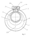
- the nominal dimensions is the end face of the respective projection 7,8 Abutment surface. It is essential that, as shown in FIG. 4, the Center of the respective circular disk-like projection 7,8 on the vertical Axis of symmetry 23 of the stripping device 1 is tangential and the upper surface line coincides with the upper surface line 13 of the arbor 4.
- the lever 5 is used to remove the blade 16 or to install a replacement blade 28 pushed up at the front by means of the trough-like end region 21, so that the fastener 30 can be released ( Figure 5).
- the Lever 5 can be dismantled as a whole, ensuring that the compression spring 20 is not lost in the process.
Landscapes
- Engineering & Computer Science (AREA)
- Mechanical Engineering (AREA)
- Surgical Instruments (AREA)
- Knives (AREA)
- Electrical Discharge Machining, Electrochemical Machining, And Combined Machining (AREA)
- Control Of Motors That Do Not Use Commutators (AREA)
- Valve Device For Special Equipments (AREA)
- High-Pressure Fuel Injection Pump Control (AREA)
- Shaping Of Tube Ends By Bending Or Straightening (AREA)
Abstract
Description
- Figur 1a, b
- in perspektivischer Darstellung ein erfindungsgemäß ausgebildetes manuelles Abmantelgerät
- Figur 2
- eine Draufsicht
- Figur 3
- einen Schnitt in Richtung A-A in Figur 2
- Figur 4
- eine Ansicht in Richtung X in Figur 3
- Figur 5
- eine perspektivische Darstellung von vorn
- Schwenken des Hebels 5 durch Niederdrücken des muldenförmig ausgebildeten Endbereiches 21.
- Aufschieben des mit einer Schutzschicht 15 versehenen Rohres 6 auf den Aufsteckdorn 4 bis zum stirnseitigen Anschlag am Gehäuse 2.
- Loslassen des Hebels 5 und Aufsetzen der Klinge 16 auf die Schutzschicht 15.
- Einmaliges oder mehrmaliges Drehen des Abmantelgerätes 1 um das Rohr 6. Dabei Einschneiden der Klinge 16 in die Schutzschicht 15. Ankratzen der metallischen Oberfläche des Rohres 6.
- Schwenken des Hebels 5 durch Niederdrücken des muldenförmig ausgebildeten Endbereiches 21.
- Abziehen des Rohres 6 vom Aufsteckdorn 4. Abstreifen des eingeschnittenen Abschnittes der Schutzschicht 15 vom metallischen Rohr 6.
- 1
- Abmantelgerät
- 2
- rohrförmiges Gehäuse
- 3
- geschlossene Stirnseite
- 4
- Aufsteckdorn
- 5
- schwenkbarer Hebel
- 6
- Rohr
- 7,8
- kreisscheibenartiger Vorsprung
- 9,9'
- Leisten
- 10
- fensterartiger Rahmen
- 11
- Mittelachse des Aufsteckdornes
- 12
- Mittelachse des Gehäuses
- 13
- obere Mantellinie des Aufsteckdornes
- 14
- obere Mantellinie des Gehäuses
- 15
- Schutzschicht
- 16
- Klinge
- 17
- Schwenkbolzen
- 18
- zapfenähnlicher Fortsatz des Hebels
- 19
- Hülse
- 20
- Druckfeder
- 21
- Endbereich des Hebels
- 22
- Abstand Klinge-Stirnseite
- 23
- vertikale Symmetrieachse
- 24
- trogförmige Vertiefung
- 25
- nasenartiger Vorsprung
- 26
- Stirnseite des Hebels
- 27
- Ausnehmung
- 28
- Ersatzklinge
- 29
- Öffnung
- 30
- Befestigungselement
Claims (12)
- Manuelles Abmantelgerät bestehend aus einem um seine Längsachse drehbaren rohrförmigen Gehäuse, an dem ein Messer befestigt ist, zum Einschneiden in eine auf einem metallischen Rohr außen angebrachte Schutzschicht in einem bestimmten Abstand von einer Stirnseite des Rohres,
dadurch gekennzeichnet,
dass an einer einen Anschlag für das Rohr (6) bildenden geschlossenen Stirnseite (3) des rohrförmigen Gehäuses (2) ein eine geringere radiale Erstreckung als das Gehäuse (2) aufweisender Aufsteckdorn (4) angeordnet ist, dessen Mittelachse (11) parallel versetzt zur Mittelachse (12) des Gehäuses (2) liegt und dessen obere Mantellinie (13) etwas unterhalb der oberen Mantellinie (14) des Gehäuses (2) sich befindet und dass im oberen Mantelbereich des Gehäuses (2) ein achsgleich zum Gehäuse (2) liegender schwenkbarer Hebel (5) angeordnet ist, der bis in den Anfangsbereich des Aufsteckdornes (4) sich erstreckt und im vorderen Endbereich des Hebels (5) als Messer eine flache mit steilen Flanken versehene Klinge (16) befestigbar ist und der Abstand (22) von der Klinge (16) bis zur geschlossenen Stirnseite (3) des Gehäuses (2) dem vorgegebenen Abstand von der Stirnseite des aufgesteckten Rohres (6) bis zur Einschnittstelle entspricht. - Manuelles Abmantelgerät nach Anspruch 1,
dadurch gekennzeichnet,
dass an der geschlossenen Stirnseite (3) des Gehäuses (2) mindestens ein kreisscheibenartig ausgebildeter Vorsprung (7,8) angeordnet ist, dessen Mittelpunkt auf der vertikalen Symmetrieachse (23) des Abmantelgerätes (1) liegt und dessen obere Mantellinie tangential mit der oberen Mantellinie (13) des Aufsteckdornes (4) zusammenfällt und der Abstand von der Klinge (16) bis zur Stirnfläche des kreisscheibenartigen Vorsprunges (7,8) dem Abstand von der Stirnseite des aufgesteckten Rohres (6) bis zum Einschnitt entspricht. - Manuelles Abmantelgerät nach Anspruch 1 und 2,
dadurch gekennzeichnet,
dass im oberen Mantelbereich des Gehäuses (2) zwei parallel zueinander liegende hochkant stehende Leisten (9,9') befestigt sind, zwischen denen der Hebel (5) schwenkbar anordenbar ist. - Manuelles Abmantelgerät nach Anspruch 3,
dadurch gekennzeichnet,
dass die beiden Leisten mit einer Querleiste verbunden sind und einen U-förmigen Trog bilden. - Manuelles Abmantelgerät nach Anspruch 3,
dadurch gekennzeichnet,
dass der obere Mantelbereich des Gehäuses (2) eine parallel zum Hebel (5) liegende muldenförmige Vertiefung (24) aufweist, die zusammen mit den beiden Leisten (9,9') einen U-förmigen Trog bilden. - Manuelles Abmantelgerät nach einem der Ansprüche 3 - 5,
dadurch gekennzeichnet,
dass am vorderen Endbereich der beiden Leisten (9,9') ein fensterartiger Rahmen (10) befestigt ist, in dessen Zwischenraum der Hebel (5) verschwenkbar ist. - Manuelles Abmantelgerät nach einem der Ansprüche 1 - 6,
dadurch gekennzeichnet,
dass im hinteren Endbereich des Hebels (5) auf der Unterseite eine eine Druckfeder (20) aufnehmende Hülse (19) angeordnet ist, deren Achse senkrecht zur Längsachse des Hebels (5) liegt, wobei die Druckfeder (20) sich mit dem anderen Ende auf der oberen Mantelfläche des Gehäuses (2) abstützt. - Manuelles Abmantelgerät nach Anspruch 6,
dadurch gekennzeichnet,
dass an der Stirnseite des fensterartigen Rahmens (10) ein nasenartiger Vorsprung (25) angeordnet ist, dessen Unterseite absatzlos in die Unterseite des Rahmens (10) übergeht. - Manuelles Abmantelgerät nach einem der Ansprüche 1 - 8,
dadurch gekennzeichnet,
dass an der dem Aufsteckdorn (4) zugewandten Stirnseite (26) des Hebels (5) eine Ausnehmung (27) zur Aufnahme der Klinge (16) vorgesehen ist. - Manuelles Abmantelgerät nach Anspruch 9,
dadurch gekennzeichnet,
dass die im Befestigungsbereich liegende Kontur der Klinge (16) mit der Kontur der Ausnehmung (27) im Hinblick auf einen seitenrichtigen Einbau der Klinge (16) aufeinander abgestimmt ist. - Manuelles Abmantelgerät nach Anspruch 9 und 10,
dadurch gekennzeichnet,
dass in der Ausnehmung (27) eine querliegende Ersatzklinge (28) anordenbar ist. - Manuelles Abmantelgerät nach den Ansprüchen 9-11,
dadurch gekennzeichnet,
dass die Klinge (16) bzw. Ersatzklinge (28) eine Öffnung (29) zum Durchstecken eines Befestigungselementes (30) aufweist.
Applications Claiming Priority (2)
| Application Number | Priority Date | Filing Date | Title |
|---|---|---|---|
| DE19961212 | 1999-12-15 | ||
| DE19961212A DE19961212C1 (de) | 1999-12-15 | 1999-12-15 | Manuelles Abmantelgerät |
Publications (2)
| Publication Number | Publication Date |
|---|---|
| EP1118405A1 true EP1118405A1 (de) | 2001-07-25 |
| EP1118405B1 EP1118405B1 (de) | 2004-10-06 |
Family
ID=7933247
Family Applications (1)
| Application Number | Title | Priority Date | Filing Date |
|---|---|---|---|
| EP00250428A Expired - Lifetime EP1118405B1 (de) | 1999-12-15 | 2000-12-12 | Manuelles Abmantelgerät |
Country Status (5)
| Country | Link |
|---|---|
| EP (1) | EP1118405B1 (de) |
| AT (1) | ATE278495T1 (de) |
| DE (2) | DE19961212C1 (de) |
| IS (1) | IS5759A (de) |
| NO (1) | NO315505B1 (de) |
Cited By (7)
| Publication number | Priority date | Publication date | Assignee | Title |
|---|---|---|---|---|
| FR2949085A1 (fr) * | 2009-08-13 | 2011-02-18 | Gdf Suez | Dispositif de grattage et procede de mise en oeuvre |
| US20110064533A1 (en) * | 2009-09-15 | 2011-03-17 | Wezag Gmbh Werkzeugfabrik | Drilling Machine Tool |
| ITVI20100086A1 (it) * | 2010-03-25 | 2011-09-26 | Ritmo Spa | Dispositivo multiutensile, particolarmente adatto alla preparazione di elementi tubolari da saldare per elettrofusione. |
| EP2990144A1 (de) * | 2014-08-29 | 2016-03-02 | ProPress GmbH | Kalibrier- und anfaswerkzeug |
| EP3520936A1 (de) | 2018-02-06 | 2019-08-07 | Georg Fischer Rohrleitungssysteme AG | Klinge für abisolier- und schneidwerkzeug |
| US11123800B2 (en) * | 2018-02-07 | 2021-09-21 | Concurrent Technologies Corporation | Pipe edge preparation tool |
| JP2023107097A (ja) * | 2022-01-21 | 2023-08-02 | 積水化学工業株式会社 | 合成樹脂管用スクレーパー |
Citations (5)
| Publication number | Priority date | Publication date | Assignee | Title |
|---|---|---|---|---|
| US3636803A (en) * | 1969-11-14 | 1972-01-25 | Cornelius C Miller | Pipe-bevelling tool |
| GB1339531A (en) * | 1972-10-02 | 1973-12-05 | Imp Eastman Uk Ltd | Tools for the preparation of hose ends |
| DE7908981U1 (de) * | 1979-03-29 | 1979-08-02 | Messer Griesheim Gmbh, 6000 Frankfurt | Rohrschaelwerkzeug |
| GB2234697A (en) * | 1989-08-12 | 1991-02-13 | Excalibur Hand Tools Ltd | Pipe end dressing device |
| EP0689928A2 (de) * | 1994-07-02 | 1996-01-03 | Thyssen Polymer Gmbh | Verfahren und Vorrichtung zur Bearbeitung von Kunststoffrohren |
-
1999
- 1999-12-15 DE DE19961212A patent/DE19961212C1/de not_active Expired - Fee Related
-
2000
- 2000-12-08 IS IS5759A patent/IS5759A/is unknown
- 2000-12-12 AT AT00250428T patent/ATE278495T1/de not_active IP Right Cessation
- 2000-12-12 EP EP00250428A patent/EP1118405B1/de not_active Expired - Lifetime
- 2000-12-12 DE DE50008097T patent/DE50008097D1/de not_active Expired - Fee Related
- 2000-12-14 NO NO20006372A patent/NO315505B1/no not_active IP Right Cessation
Patent Citations (5)
| Publication number | Priority date | Publication date | Assignee | Title |
|---|---|---|---|---|
| US3636803A (en) * | 1969-11-14 | 1972-01-25 | Cornelius C Miller | Pipe-bevelling tool |
| GB1339531A (en) * | 1972-10-02 | 1973-12-05 | Imp Eastman Uk Ltd | Tools for the preparation of hose ends |
| DE7908981U1 (de) * | 1979-03-29 | 1979-08-02 | Messer Griesheim Gmbh, 6000 Frankfurt | Rohrschaelwerkzeug |
| GB2234697A (en) * | 1989-08-12 | 1991-02-13 | Excalibur Hand Tools Ltd | Pipe end dressing device |
| EP0689928A2 (de) * | 1994-07-02 | 1996-01-03 | Thyssen Polymer Gmbh | Verfahren und Vorrichtung zur Bearbeitung von Kunststoffrohren |
Cited By (9)
| Publication number | Priority date | Publication date | Assignee | Title |
|---|---|---|---|---|
| FR2949085A1 (fr) * | 2009-08-13 | 2011-02-18 | Gdf Suez | Dispositif de grattage et procede de mise en oeuvre |
| US20110064533A1 (en) * | 2009-09-15 | 2011-03-17 | Wezag Gmbh Werkzeugfabrik | Drilling Machine Tool |
| ITVI20100086A1 (it) * | 2010-03-25 | 2011-09-26 | Ritmo Spa | Dispositivo multiutensile, particolarmente adatto alla preparazione di elementi tubolari da saldare per elettrofusione. |
| EP2368656A1 (de) * | 2010-03-25 | 2011-09-28 | RITMO S.p.A. | Mehrfachwerkzeugvorrichtung zur Vorbereitung rohrförmiger Elemente, die durch Elektroschmelzen geschweisst werden sollen |
| US9021926B2 (en) | 2010-03-25 | 2015-05-05 | Ritmo S.P.A. | Multiple tool device for preparing tubular elements to be welded by electrofusion |
| EP2990144A1 (de) * | 2014-08-29 | 2016-03-02 | ProPress GmbH | Kalibrier- und anfaswerkzeug |
| EP3520936A1 (de) | 2018-02-06 | 2019-08-07 | Georg Fischer Rohrleitungssysteme AG | Klinge für abisolier- und schneidwerkzeug |
| US11123800B2 (en) * | 2018-02-07 | 2021-09-21 | Concurrent Technologies Corporation | Pipe edge preparation tool |
| JP2023107097A (ja) * | 2022-01-21 | 2023-08-02 | 積水化学工業株式会社 | 合成樹脂管用スクレーパー |
Also Published As
| Publication number | Publication date |
|---|---|
| NO315505B1 (no) | 2003-09-15 |
| DE50008097D1 (de) | 2004-11-11 |
| EP1118405B1 (de) | 2004-10-06 |
| NO20006372D0 (no) | 2000-12-14 |
| DE19961212C1 (de) | 2002-01-31 |
| NO20006372L (no) | 2001-06-18 |
| ATE278495T1 (de) | 2004-10-15 |
| IS5759A (is) | 2001-06-15 |
Similar Documents
| Publication | Publication Date | Title |
|---|---|---|
| DE69510451T2 (de) | Handwerkzeug | |
| DE8408795U1 (de) | Vorrichtung zum Verbinden eines Blechs mit einem perforierten Blech | |
| DE3887177T2 (de) | Schneidvorrichtung für Kunststoffrohre mit geführtem Messer. | |
| DE102011056040A1 (de) | Vorrichtung zum Ablängen von Wellrohren | |
| CH663861A5 (de) | Abisolierzange fuer leiterenden. | |
| EP1118405B1 (de) | Manuelles Abmantelgerät | |
| DE3141248C2 (de) | Einrichtung zum Zuführen von Schrauben für einen motorbetriebenen Schraubenzieher | |
| DE60013493T2 (de) | Rohrbearbeitungsvorrichtung | |
| EP2653791B1 (de) | Vorrichtung zum Befestigen von Rohren | |
| DE3131224A1 (de) | "umreifungsgeraet fuer stahlbaender" | |
| WO2012025107A2 (de) | Gerätehalter | |
| EP1295688A2 (de) | Vorrichtung sowie Verfahren zum trennen von Rohren | |
| EP2567796B1 (de) | Handgriff | |
| DE1450967C3 (de) | Kopfloser Bolzen mit am einen Ende hebelartig abstehender Befestigungslasche als Axialschubsicherung | |
| DE102004018429B4 (de) | Vorrichtung zum Aufbringen einer axialen Preßkraft | |
| DE19500128B4 (de) | Zwinge für das Bauwesen | |
| DE9216760U1 (de) | Markiergerät zum Anbringen von Markierungen an Rohrmänteln | |
| DE29712879U1 (de) | Lochzange | |
| DE102004016753B4 (de) | Vorrichtung und Verfahren zum Entfernen eines Korkens aus einem Flaschenhals | |
| DE202011106374U1 (de) | Halteelement für eine Schellenfixierung | |
| DE2737888A1 (de) | Schere, insbesondere gartenschere | |
| DE2716841B2 (de) | Schneidwerkzeug für Kunststoffrohre | |
| DE9317428U1 (de) | Schälvorrichtung für Industriewürste | |
| DE102006011677A1 (de) | Markierungsvorrichtung zur Markierung von Soll-Schnittstellen an gefällten Baumstämmen | |
| EP2077175B1 (de) | Rohrtrennwerkzeug |
Legal Events
| Date | Code | Title | Description |
|---|---|---|---|
| PUAI | Public reference made under article 153(3) epc to a published international application that has entered the european phase |
Free format text: ORIGINAL CODE: 0009012 |
|
| AK | Designated contracting states |
Kind code of ref document: A1 Designated state(s): AT BE CH CY DE DK ES FI FR GB GR IE IT LI LU MC NL PT SE TR |
|
| AX | Request for extension of the european patent |
Free format text: AL;LT;LV;MK;RO;SI |
|
| 17P | Request for examination filed |
Effective date: 20010718 |
|
| AKX | Designation fees paid |
Free format text: AT BE CH CY DE DK ES FI FR GB GR IE IT LI LU MC NL PT SE TR |
|
| RAP1 | Party data changed (applicant data changed or rights of an application transferred) |
Owner name: STRAWA AG |
|
| GRAP | Despatch of communication of intention to grant a patent |
Free format text: ORIGINAL CODE: EPIDOSNIGR1 |
|
| GRAS | Grant fee paid |
Free format text: ORIGINAL CODE: EPIDOSNIGR3 |
|
| GRAA | (expected) grant |
Free format text: ORIGINAL CODE: 0009210 |
|
| AK | Designated contracting states |
Kind code of ref document: B1 Designated state(s): AT BE CH CY DE DK ES FI FR GB GR IE IT LI LU MC NL PT SE TR |
|
| PG25 | Lapsed in a contracting state [announced via postgrant information from national office to epo] |
Ref country code: GB Free format text: LAPSE BECAUSE OF FAILURE TO SUBMIT A TRANSLATION OF THE DESCRIPTION OR TO PAY THE FEE WITHIN THE PRESCRIBED TIME-LIMIT Effective date: 20041006 Ref country code: IT Free format text: LAPSE BECAUSE OF FAILURE TO SUBMIT A TRANSLATION OF THE DESCRIPTION OR TO PAY THE FEE WITHIN THE PRESCRIBED TIME-LIMIT;WARNING: LAPSES OF ITALIAN PATENTS WITH EFFECTIVE DATE BEFORE 2007 MAY HAVE OCCURRED AT ANY TIME BEFORE 2007. THE CORRECT EFFECTIVE DATE MAY BE DIFFERENT FROM THE ONE RECORDED. Effective date: 20041006 Ref country code: SE Free format text: LAPSE BECAUSE OF FAILURE TO SUBMIT A TRANSLATION OF THE DESCRIPTION OR TO PAY THE FEE WITHIN THE PRESCRIBED TIME-LIMIT Effective date: 20041006 Ref country code: NL Free format text: LAPSE BECAUSE OF FAILURE TO SUBMIT A TRANSLATION OF THE DESCRIPTION OR TO PAY THE FEE WITHIN THE PRESCRIBED TIME-LIMIT Effective date: 20041006 Ref country code: TR Free format text: LAPSE BECAUSE OF FAILURE TO SUBMIT A TRANSLATION OF THE DESCRIPTION OR TO PAY THE FEE WITHIN THE PRESCRIBED TIME-LIMIT Effective date: 20041006 Ref country code: CY Free format text: LAPSE BECAUSE OF FAILURE TO SUBMIT A TRANSLATION OF THE DESCRIPTION OR TO PAY THE FEE WITHIN THE PRESCRIBED TIME-LIMIT Effective date: 20041006 Ref country code: FR Free format text: LAPSE BECAUSE OF NON-PAYMENT OF DUE FEES Effective date: 20041006 Ref country code: FI Free format text: LAPSE BECAUSE OF FAILURE TO SUBMIT A TRANSLATION OF THE DESCRIPTION OR TO PAY THE FEE WITHIN THE PRESCRIBED TIME-LIMIT Effective date: 20041006 Ref country code: IE Free format text: LAPSE BECAUSE OF FAILURE TO SUBMIT A TRANSLATION OF THE DESCRIPTION OR TO PAY THE FEE WITHIN THE PRESCRIBED TIME-LIMIT Effective date: 20041006 |
|
| REG | Reference to a national code |
Ref country code: GB Ref legal event code: FG4D Free format text: NOT ENGLISH |
|
| REG | Reference to a national code |
Ref country code: CH Ref legal event code: EP |
|
| REG | Reference to a national code |
Ref country code: IE Ref legal event code: FG4D Free format text: GERMAN |
|
| REF | Corresponds to: |
Ref document number: 50008097 Country of ref document: DE Date of ref document: 20041111 Kind code of ref document: P |
|
| PG25 | Lapsed in a contracting state [announced via postgrant information from national office to epo] |
Ref country code: LU Free format text: LAPSE BECAUSE OF NON-PAYMENT OF DUE FEES Effective date: 20041212 |
|
| PG25 | Lapsed in a contracting state [announced via postgrant information from national office to epo] |
Ref country code: MC Free format text: LAPSE BECAUSE OF NON-PAYMENT OF DUE FEES Effective date: 20041231 Ref country code: BE Free format text: LAPSE BECAUSE OF NON-PAYMENT OF DUE FEES Effective date: 20041231 |
|
| REG | Reference to a national code |
Ref country code: CH Ref legal event code: NV Representative=s name: RIEDERER HASLER & PARTNER PATENTANWAELTE AG |
|
| PG25 | Lapsed in a contracting state [announced via postgrant information from national office to epo] |
Ref country code: GR Free format text: LAPSE BECAUSE OF FAILURE TO SUBMIT A TRANSLATION OF THE DESCRIPTION OR TO PAY THE FEE WITHIN THE PRESCRIBED TIME-LIMIT Effective date: 20050106 Ref country code: DK Free format text: LAPSE BECAUSE OF FAILURE TO SUBMIT A TRANSLATION OF THE DESCRIPTION OR TO PAY THE FEE WITHIN THE PRESCRIBED TIME-LIMIT Effective date: 20050106 |
|
| PG25 | Lapsed in a contracting state [announced via postgrant information from national office to epo] |
Ref country code: ES Free format text: LAPSE BECAUSE OF FAILURE TO SUBMIT A TRANSLATION OF THE DESCRIPTION OR TO PAY THE FEE WITHIN THE PRESCRIBED TIME-LIMIT Effective date: 20050117 |
|
| NLV1 | Nl: lapsed or annulled due to failure to fulfill the requirements of art. 29p and 29m of the patents act | ||
| GBV | Gb: ep patent (uk) treated as always having been void in accordance with gb section 77(7)/1977 [no translation filed] |
Effective date: 20041006 |
|
| REG | Reference to a national code |
Ref country code: IE Ref legal event code: FD4D |
|
| BERE | Be: lapsed |
Owner name: STRAWA A.G. Effective date: 20041231 |
|
| PLBE | No opposition filed within time limit |
Free format text: ORIGINAL CODE: 0009261 |
|
| STAA | Information on the status of an ep patent application or granted ep patent |
Free format text: STATUS: NO OPPOSITION FILED WITHIN TIME LIMIT |
|
| 26N | No opposition filed |
Effective date: 20050707 |
|
| EN | Fr: translation not filed | ||
| BERE | Be: lapsed |
Owner name: STRAWA A.G. Effective date: 20041231 |
|
| PG25 | Lapsed in a contracting state [announced via postgrant information from national office to epo] |
Ref country code: PT Free format text: LAPSE BECAUSE OF NON-PAYMENT OF DUE FEES Effective date: 20050306 |
|
| PGFP | Annual fee paid to national office [announced via postgrant information from national office to epo] |
Ref country code: CH Payment date: 20081021 Year of fee payment: 9 |
|
| PGFP | Annual fee paid to national office [announced via postgrant information from national office to epo] |
Ref country code: AT Payment date: 20081215 Year of fee payment: 9 |
|
| PGFP | Annual fee paid to national office [announced via postgrant information from national office to epo] |
Ref country code: DE Payment date: 20081219 Year of fee payment: 9 |
|
| REG | Reference to a national code |
Ref country code: CH Ref legal event code: PL |
|
| PG25 | Lapsed in a contracting state [announced via postgrant information from national office to epo] |
Ref country code: AT Free format text: LAPSE BECAUSE OF NON-PAYMENT OF DUE FEES Effective date: 20091212 |
|
| PG25 | Lapsed in a contracting state [announced via postgrant information from national office to epo] |
Ref country code: CH Free format text: LAPSE BECAUSE OF NON-PAYMENT OF DUE FEES Effective date: 20091231 Ref country code: LI Free format text: LAPSE BECAUSE OF NON-PAYMENT OF DUE FEES Effective date: 20091231 |
|
| PG25 | Lapsed in a contracting state [announced via postgrant information from national office to epo] |
Ref country code: DE Free format text: LAPSE BECAUSE OF NON-PAYMENT OF DUE FEES Effective date: 20100701 |