EP3520936A1 - Klinge für abisolier- und schneidwerkzeug - Google Patents
Klinge für abisolier- und schneidwerkzeug Download PDFInfo
- Publication number
- EP3520936A1 EP3520936A1 EP18155222.5A EP18155222A EP3520936A1 EP 3520936 A1 EP3520936 A1 EP 3520936A1 EP 18155222 A EP18155222 A EP 18155222A EP 3520936 A1 EP3520936 A1 EP 3520936A1
- Authority
- EP
- European Patent Office
- Prior art keywords
- blade
- base body
- insert
- cutting edge
- insert blade
- Prior art date
- Legal status (The legal status is an assumption and is not a legal conclusion. Google has not performed a legal analysis and makes no representation as to the accuracy of the status listed.)
- Granted
Links
Images

Classifications
-
- B—PERFORMING OPERATIONS; TRANSPORTING
- B26—HAND CUTTING TOOLS; CUTTING; SEVERING
- B26D—CUTTING; DETAILS COMMON TO MACHINES FOR PERFORATING, PUNCHING, CUTTING-OUT, STAMPING-OUT OR SEVERING
- B26D3/00—Cutting work characterised by the nature of the cut made; Apparatus therefor
- B26D3/28—Splitting layers from work; Mutually separating layers by cutting
-
- B—PERFORMING OPERATIONS; TRANSPORTING
- B23—MACHINE TOOLS; METAL-WORKING NOT OTHERWISE PROVIDED FOR
- B23B—TURNING; BORING
- B23B5/00—Turning-machines or devices specially adapted for particular work; Accessories specially adapted therefor
- B23B5/16—Turning-machines or devices specially adapted for particular work; Accessories specially adapted therefor for bevelling, chamfering, or deburring the ends of bars or tubes
- B23B5/161—Devices attached to the workpiece
- B23B5/162—Devices attached to the workpiece with an internal clamping device
-
- B—PERFORMING OPERATIONS; TRANSPORTING
- B26—HAND CUTTING TOOLS; CUTTING; SEVERING
- B26D—CUTTING; DETAILS COMMON TO MACHINES FOR PERFORATING, PUNCHING, CUTTING-OUT, STAMPING-OUT OR SEVERING
- B26D1/00—Cutting through work characterised by the nature or movement of the cutting member or particular materials not otherwise provided for; Apparatus or machines therefor; Cutting members therefor
- B26D1/0006—Cutting members therefor
-
- B—PERFORMING OPERATIONS; TRANSPORTING
- B26—HAND CUTTING TOOLS; CUTTING; SEVERING
- B26D—CUTTING; DETAILS COMMON TO MACHINES FOR PERFORATING, PUNCHING, CUTTING-OUT, STAMPING-OUT OR SEVERING
- B26D1/00—Cutting through work characterised by the nature or movement of the cutting member or particular materials not otherwise provided for; Apparatus or machines therefor; Cutting members therefor
- B26D1/01—Cutting through work characterised by the nature or movement of the cutting member or particular materials not otherwise provided for; Apparatus or machines therefor; Cutting members therefor involving a cutting member which does not travel with the work
- B26D1/04—Cutting through work characterised by the nature or movement of the cutting member or particular materials not otherwise provided for; Apparatus or machines therefor; Cutting members therefor involving a cutting member which does not travel with the work having a linearly-movable cutting member
-
- B—PERFORMING OPERATIONS; TRANSPORTING
- B26—HAND CUTTING TOOLS; CUTTING; SEVERING
- B26D—CUTTING; DETAILS COMMON TO MACHINES FOR PERFORATING, PUNCHING, CUTTING-OUT, STAMPING-OUT OR SEVERING
- B26D3/00—Cutting work characterised by the nature of the cut made; Apparatus therefor
- B26D3/001—Cutting tubes longitudinally
-
- B—PERFORMING OPERATIONS; TRANSPORTING
- B26—HAND CUTTING TOOLS; CUTTING; SEVERING
- B26D—CUTTING; DETAILS COMMON TO MACHINES FOR PERFORATING, PUNCHING, CUTTING-OUT, STAMPING-OUT OR SEVERING
- B26D3/00—Cutting work characterised by the nature of the cut made; Apparatus therefor
- B26D3/28—Splitting layers from work; Mutually separating layers by cutting
- B26D3/282—Splitting layers from work; Mutually separating layers by cutting by peeling-off
-
- B—PERFORMING OPERATIONS; TRANSPORTING
- B23—MACHINE TOOLS; METAL-WORKING NOT OTHERWISE PROVIDED FOR
- B23B—TURNING; BORING
- B23B2220/00—Details of turning, boring or drilling processes
- B23B2220/40—Peeling
-
- B—PERFORMING OPERATIONS; TRANSPORTING
- B26—HAND CUTTING TOOLS; CUTTING; SEVERING
- B26D—CUTTING; DETAILS COMMON TO MACHINES FOR PERFORATING, PUNCHING, CUTTING-OUT, STAMPING-OUT OR SEVERING
- B26D1/00—Cutting through work characterised by the nature or movement of the cutting member or particular materials not otherwise provided for; Apparatus or machines therefor; Cutting members therefor
- B26D1/0006—Cutting members therefor
- B26D2001/0053—Cutting members therefor having a special cutting edge section or blade section
-
- B—PERFORMING OPERATIONS; TRANSPORTING
- B26—HAND CUTTING TOOLS; CUTTING; SEVERING
- B26D—CUTTING; DETAILS COMMON TO MACHINES FOR PERFORATING, PUNCHING, CUTTING-OUT, STAMPING-OUT OR SEVERING
- B26D1/00—Cutting through work characterised by the nature or movement of the cutting member or particular materials not otherwise provided for; Apparatus or machines therefor; Cutting members therefor
- B26D1/0006—Cutting members therefor
- B26D2001/006—Cutting members therefor the cutting blade having a special shape, e.g. a special outline, serrations
Definitions
- the invention relates to a blade for a stripping and peeling tool for stripping and peeling a pre-insulated tube comprising a base body, wherein the base body is formed as an elongated, thin plate, wherein the plate is convex and the apex of the convex curvature along the length of the Plate extends, wherein on a longitudinal edge of the plate or the base body, a cutting edge is arranged, which serves to release the insulating layer from the inner tube and an insert blade.
- Abmanteletti are also known from the prior art for stripping a metal tube provided with a protective layer.
- the EP 1 118 405 A1 discloses such a device.
- both devices mentioned above are not suitable for stripping and peeling a pre-insulated pipe, which usually includes a slightly thicker foam insulation, which is to be separated from the inner tube and then to rework the outer casing tube surface of the inner tube so that the surface is suitable for a Welding is suitable.
- pre-insulated pipelines are used where it requires a good isolation of the medium from the ambient conditions, for example.
- an insulating layer is preferably arranged from foamed plastic, wherein the insulating layer is surrounded by an outer skin or an outer tube, which preferably made of plastic but also of a metal and serves to protect the insulation layer.
- Such pipes must be stripped at their ends and the medium pipe to be peeled on the outer surface to be connected to fittings or other pipes can, as the connection is made via the medium pipe to ensure the tightness.
- the EP 3 213 890 A1 discloses a tool with which a stripping and peeling a pre-insulated pipe is possible.
- the blade used allows both the stripping by separating the insulation layer, as well as the peeling of the outer surface of the inner tube.
- a disadvantage of the above-mentioned embodiment, however, is that the blade or the blades arranged thereon are rigidly aligned and can not adapt to the outer lateral surface of the inner tube.
- the insert blade is formed as a separate part and the blade includes an axis, wherein the axis of storage of the insert blade in the base body and preferably protrudes through the insert blade, wherein the insert blade has a cutting edge and the insert blade so in Basic body is arranged so that the cutting edge of the insert blade runs parallel to the cutting edge on the base body.
- the inventive blade for stripping and peeling a pre-insulated pipe includes a base body, wherein the base body is formed as an elongated, thin plate.
- the plate has over the entire length a convex configuration, that is, the plate has on its inner side, which is aligned towards the inner tube, a curvature preferably to a radius as well as on the outside, the two curvatures preferably radii preferably run concentrically. Due to the convex configuration of the plate, the apex of the curvature preferably extends along the length of the plate or the Grundgropers radius.
- a cutting edge is arranged, wherein the cutting edge serves to release the insulating layer from the inner tube.
- the blade is rotated on one side or in the one direction of rotation and the subsequent peeling is preferably carried out by means of a rotation in the opposite direction, wherein the peeling can also take place during the rotation or the release of the insulating layer.
- the blade includes an insert blade which is formed as a separate part and is arranged in the base body.
- the insert blade is mounted in the base body by means of an axle, which projects through the insert blade, whereby the insert blade has the opportunity to move up and down and is guided on the left and right of the main body.
- the cutting blade disposed on the insert blade is aligned parallel to the cutting edge on the base body, wherein it is aligned in the opposite or the same direction as the cutting edge on the base body.
- the base body has a recess in which the insert blade is arranged.
- the insert blade is optimally guided and aligned.
- the recess in the main body is formed continuously and is completely enclosed by the main body. This means that the recess penetrates the base body or the plate completely and is surrounded on all sides by the base body, so that the base frame framed the recess. This has the advantage that the body is stable in itself and has no noses or corners that stand separately and get caught with the insulation layer.
- the blade has a spring element which serves to press the insert blade. Since the insert blade is mounted on the axle, the insert blade has the ability to move up and down to adapt to the outer surface of the inner tube. In order to exert a certain bias on the insert blade or to achieve a force to peel the outer lateral surface, the spring element presses down the insert blade or against the inner tube. The insulating layer which runs above the blade also exerts a contact pressure on the blade which serves for the peeling process.
- the invention is also distinguished by the fact that the base body has a thickness of only 1 to 4 mm, especially preferably 1.5 to 3 mm, thereby permitting piercing into the insulating layer. Moreover, it is advantageous if the base body has a bevel on the two longitudinal sides and preferably on the front side. The bevels on the long side allow the insulation a better sliding over the blade and the slope on the front side reduce the resistance when piercing the insulation layer.
- the insert blade has a gradation of the thickness or of different heights over the length of the insert blade.
- the inner surface of the insert blade facing the inner tube to be peeled has different heights. This serves to ensure that the cutting edge comes into contact with the outer lateral surface, even if the rear region or the Exceptional range of the insert blade when peeling first on the not yet peeled outer lateral surface moves, which still has a larger diameter than the finally peeled diameter. Due to the height differences ensures that the cutting edge or the peeling area of the insert blade can still engage sufficiently deep in the lateral surface to ablate material, since the cutting edge is higher than the rear portion of the blade serves as an exception and rests only on the outer surface if no deeper peeling is more desirable.
- the peeling area projects beyond the exceptional range between 0.2-0.8 mm, especially preferably 0.2-0.5 mm. In height on the inner surface of the insert blade.
- the insert blade has different areas on the inner surface, which preferably have different heights.
- the areas serve a different purpose as previously mentioned.
- the insert blade has, on the one hand, a peeling region on which the cutting edge is arranged and, on the other hand, at least one exception region, which is arranged behind the peeling region. At the height of the peeling area or the cutting edge dominates the exception area to a peel.
- a contact area is arranged on the insert blade, which is preferably arranged in front of the peeling area or in front of the cutting edge.
- the insert blade preferably in the front region has a support region for supporting the insert blade at the end of the peeling process or the unscrewing of the blade. This avoids that the cutting edge digs into the lateral surface at the end of the pipe, but rather that the peeling ends straight.
- a preferred embodiment is that the cutting edge on the base body and the cutting edge on the insert blade runs parallel to the tube axis of the pipe to be removed, this allows easy stripping and peeling with a tool in one clamping.
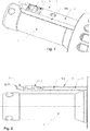
- FIG. 1 The drawing shows the blade 1 according to the invention in a corresponding tool for ablation and peeling of pre-insulated pipelines.
- the pipe end to be stripped is plugged and the blade 1 according to the invention is then screwed by a rotational movement in the insulating layer of the pre-insulated pipe.
- the ones shown here Fig. 1 and 2 show the blade 1 in the position in which it is completely immersed in the tube, in which case the tube is not shown to show the blade clearly visible.
- the blade 1 does not yet protrude beyond the mandrel 4 but rises slowly over the rotational movement in the position shown.
- the blade 1 includes a base body 2 which is preferably made of a metallic material.
- the main body 2 has a shape as an elongated, thin plate, which has a convex curvature.
- the convex curvature on the outside 5 is good in the 4 and 5 recognizable.
- the curvature 5, which is preferably formed as a radius, has the advantage that the separated insulating layer easily slides over the blade 1 as it continues to penetrate into the insulating layer as well as in the Unscrew the blade 1 during the peeling process.
- a convex curvature 6 is also arranged, which is also preferably formed as a radius, whereby the blade 1 and the base body 2 good on the outer surface of the inner tube applies and so good insulation and peeling can be done ,
- the vertex 7 of the convex curvature 5 extends parallel to the length of the main body 2 and the plate.
- a cutting edge 8 which serves for stripping or loosening the insulating layer of the outer lateral surface of the inner tube (not shown).
- the cutting edge 8 extends over the entire length of the basic body 2.
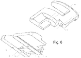
- the blade 1 includes an insert blade 3, which is formed as a separate part, which works well in Fig. 6 is recognizable.
- the insert blade 3 is arranged or mounted in the base body 2.
- the axis 9 protrudes through the insert blade 3 and thereby allows the insert blade 3 a pivotal movement down and up to adapt well to the outer surface of the inner tube during the peeling process.
- the insert blade 3 has a cutting edge 10, which serves for peeling the outer lateral surface of the inner tube.
- the insert blade 3 is arranged in the base body 2 such that the cutting edge 10 of the insert blade 3 runs parallel to the cutting edge 8 on the base body 3 and the cutting edge 10 of the inserting blade 3 is aligned in the opposite or the same direction of the cutting edge 8 on the base body 2.
- the oppositely disposed cutting edges 8, 10 are due to the fact that the stripping or separating the insulating layer from the inner tube in one direction of rotation and the subsequent peeling in the other direction of rotation, whereby the blade 1 is screwed out of the tube again.
- the peeling takes place during the stripping as during the same rotation process, consequently the screwing in.
- the main body 2 has a recess 11 in which the insert blade 3 is arranged.
- the recess 11 is formed continuously so that the inserted therein insert blade 3 protrudes and the outer surface of the Inner tube can contact.
- the recess 11 completely surrounded by the base body 2, that is, it is open on each side and thus completely framed by the base body 2, whereby the complete body 2 has good stability and rigidity as well as no protruding elements with could get caught up in isolation.
- the insert blade 3 is preferably additionally pressed down by means of a spring element 12, in addition to that the insulating layer also presses on the insert blade 3 while it slides during the peeling operation when unscrewing the blade over the base body 2.
- the insert blade 3 has on its inner surface 13, which faces the inner tube to be peeled a height gradation, this is good in Fig. 3 to recognize.
- the peeling area is designed to be higher than the exceptional area 15 lying behind or also the supporting area 19 lying in front. Since the inner tube is peeled during the unscrewing of the blade 1, the exceptional area 15 is above the unheated tube, which thus has a larger one Outer diameter has.
- the exception region 15 has a lower height than the peeling region 13.
- the inserting blade 3 in front of the peeling region 13 has a bearing region 19 which prevents the peeling region 14 or The cutting edge 10 digs into the tube at the end of the tube since there is no possibility of support through the exception region 15 since this is already outside the tube.
- Fig. 5 is clearly visible as the insert blade 3 is mounted on the axis 9 in the base body 2.
- the base body 2 has a stop on which limits the rotational movement of the insert blade 3 down, wherein the stop is not shown in the figures.
Landscapes
- Engineering & Computer Science (AREA)
- Mechanical Engineering (AREA)
- Life Sciences & Earth Sciences (AREA)
- Forests & Forestry (AREA)
- Knives (AREA)
- Removal Of Insulation Or Armoring From Wires Or Cables (AREA)
Abstract
Description
- Die Erfindung betrifft eine Klinge für ein Abisolier- und Schälwerkzeug zum Abisolieren und Schälen eines vorisolierten Rohres beinhaltend einen Grundkörper, wobei der Grundkörper als längliche, dünne Platte ausgebildet ist, wobei die Platte konvex ausgebildet ist und sich der Scheitelpunkt der konvexen Krümmung entlang der Länge der Platte erstreckt, wobei an einer Längskante der Platte bzw. des Grundkörpers eine Schneide angeordnet ist, die dem Lösen der Isolationsschicht vom Innenrohr dient und eine Einsatzklinge.
- Aus dem Stand der Technik sind hauptsächlich Schälgeräte für Mantelaussenflächen von Rohren bekannt um die äussere oxidierte Schichten abzuschälen, um optimale Verschweissungen mit einem Fitting durchführen zu können. Damit die Verschweissung den geforderten Anforderungen stand hält und da diese nur erzielbar sind wenn die Mantelaussenfläche keine Verunreinigungen und keine Oxidschicht aufweist, ist es wichtig die äusserste Schicht zu entfernen. Die
JP 6-79501 - Aus dem Stand der Technik sind auch Abmantelgeräte bekannt zur Abmantelung eines mit einer Schutzschicht versehenen Metallrohres. Die
EP 1 118 405 A1 offenbart ein solches Gerät. - Beide oben erwähnten Vorrichtungen eignen sich jedoch nicht zum Abisolieren und Schälen eines vorisolierten Rohres, welches in der Regel eine etwas dickere Schaumstoffisolation beinhaltet, die es vom Innenrohr abzutrennen gilt und anschliessend die äussere Mantelrohrfläche des Innenrohres noch derart zu überarbeiten, dass die Oberfläche sich für eine Schweissung eignet.
Solche vorisolierten Rohrleitungen werden dort eingesetzt wo es eine gute Isolation des Mediums gegenüber den Umgebungsbedingungen benötigt, bspw. für den Transport von Kälteträgermedien in Kühlsystemen. Um das Medium transportierende Innenrohr bzw. das Mediumsrohr vorzugsweise aus Kunststoff ist eine Isolationsschicht vorzugweise aus geschäumtem Kunststoff angeordnet, wobei die Isolationsschicht von einer Aussenhaut oder einem Aussenrohr umgeben ist, welche vorzugsweise aus Kunststoff aber auch aus einem Metall gebildet sind und dem Schutz der Isolationsschicht dient. Solche Rohrleitungen müssen an ihren Enden abisoliert und das Mediumsrohr an der äusseren Mantelfläche geschält werden um mit Fittings oder weiteren Rohren verbunden werden zu können, da die Verbindung über das Mediumsrohr erfolgt um die Dichtheit zu gewährleisten. - Die
EP 3 213 890 A1 offenbart ein Werkzeug mit welchem ein Abisolieren und Schälen eines vorisolierten Rohres möglich ist. Die verwendete Klinge ermöglicht sowohl das Abisolieren durch Abtrennen der Isolationsschicht, wie auch das Schälen der Aussenmantelfläche des Innenrohres.
Nachteilig an der oben erwähnten Ausführungsform ist jedoch, dass die Klinge bzw. die daran angeordneten Schneiden starr ausgerichtet sind und sich der äusseren Mantelfläche des Innenrohres nicht anpassen können. - Es ist Aufgabe der Erfindung eine Klinge vorzuschlagen, welche sich für das Abisolieren und Schälen von vorisolierten Rohrenden eignet und eine optimale Schälung der äusseren Mantelfläche gewährleistet sowie einen wirtschaftlich optimalen Prozess ermöglicht mittels dem Vorgang effizient durchgeführt werden kann.
- Diese Aufgabe wird erfindungsgemäss dadurch gelöst, dass die Einsatzklinge als separates Teil ausgebildet ist und die Klinge eine Achse beinhaltet, wobei die Achse der Lagerung der Einsatzklinge im Grundkörper dient und vorzugsweise durch die Einsatzklinge hindurchragt, wobei die Einsatzklinge eine Schneide aufweist und die Einsatzklinge derart im Grundkörper angeordnet ist, dass die Schneide der Einsatzklinge parallel zur Schneide am Grundkörper verläuft.
- Die erfindungsgemässe Klinge zur Abisolierung und Schälung eines vorisolierten Rohres beinhaltet einen Grundkörper, wobei der Grundkörper als längliche, dünne Platte ausgebildet ist. Die Platte hat über die komplette Länge eine konvexe Ausgestaltung, das heisst die Platte weist an ihrer Innenseite, welche zum Innenrohr hin ausgerichtet ist, eine Krümmung auf vorzugsweise einen Radius wie auch an der Aussenseite, wobei die beiden Krümmungen vorzugsweise Radien vorzugsweise konzentrisch verlaufen. Durch die konvexe Ausgestaltung der Platte erstreckt sich der Scheitelpunkt der Krümmung vorzugsweise Radius entlang der Länge der Platte bzw. des Grundköpers. An der Längskante des Grundkörpers bzw. der Platte ist eine Schneide angeordnet, wobei die Schneide dem Lösen der Isolationsschicht vom Innenrohr dient. Zum Lösen der Isolationsschicht, wird die Klinge auf die eine Seite rotiert bzw. in die eine Drehrichtung und das anschliessende Schälen wird vorzugsweise mittels einer Rotation in die Gegenrichtung durchgeführt, wobei das Schälen auch während der Rotation bzw. dem Lösen der Isolationsschicht erfolgen kann.
Die Klinge beinhaltet eine Einsatzklinge, welche als separates Teil ausgebildet ist und im Grundkörper angeordnet ist. Die Einsatzklinge ist mittels einer Achse, welche durch die Einsatzklinge hindurch ragt, im Grundkörper gelagert, wodurch die Einsatzklinge die Möglichkeit hat sich nach oben und nach unten zu bewegen und links und rechts vom Grundkörper geführt ist.
Die an der Einsatzklinge angeordnete Schneide ist parallel zur Schneide am Grundkörper ausgerichtet, wobei sie in die entgegengesetzte oder dieselbe Richtung wie die Schneide am Grundkörper ausgerichtet ist. Durch die gegengleiche bzw. entgegengesetzte Ausrichtung der beiden Schneiden zueinander wird erreicht, dass das Lösen der Isolationsschicht vom Innenrohr während dem Hineindrehen der Klinge in die eine Drehrichtung erfolgt, das heisst mit oder gegen den Uhrzeigersinn, und das anschliessende Schälen erfolgt dann während dem Herausdrehen der Klinge und in die entgegengesetzte Dreh- bzw. Rotationsrichtung. Wenn die Schneiden an der Klinge bzw. am Grundkörper und an der Einsatzklinge hingegen in dieselbe Richtung ausgerichtet sind, erfolgt die Schälung des Innenrohres während des Lösens der Isolationsschicht also auch während des Hineindrehens der Klinge. In beiden Fällen können dadurch unnötige Bewegungsvorgänge während des Prozesses vermieden werden, wodurch der Vorgang effizient durchgeführt werden kann. - Vorzugsweise weist der Grundkörper eine Aussparung auf in der die Einsatzklinge angeordnet ist. Durch das Anordnen der Einsatzklinge in der Aussparung ist die Einsatzklinge optimal geführt und ausgerichtet.
- Vorteilhaft ist es, dass die Aussparung im Grundkörper durchgehend ausgebildet ist und vollständig vom Grundkörper umschlossen ist. Das heisst die Aussparung durchdringt den Grundkörper bzw. die Platte vollständig und ist auf allen Seiten vom Grundkörper umgeben, so dass der Grundkörper die Aussparung umrahmt. Dies bringt den Vorteil mit sich, dass der Grundkörper in sich stabil ist und keine Nasen oder Ecken aufweist, die separat abstehen und sich mit der Isolationsschicht verhaken.
- Gemäss einer bevorzugten Ausführungsform weist die Klinge ein Federelement auf, welches dem Anpressen der Einsatzklinge dient. Da die Einsatzklinge auf der Achse gelagert ist, hat die Einsatzklinge die Möglichkeit sich nach unten und oben zu bewegen um sich der äusseren Mantelfläche des Innenrohres anzupassen. Um nun eine gewisse Vorspannung auf die Einsatzklinge auszuüben bzw. eine Kraft um eine Schälung der äusseren Mantelfläche zu erreichen, drückt das Federelement die Einsatzklinge hinunter bzw. an das Innenrohr. Die Isolationsschicht welche oberhalb der Klinge verläuft übt ebenso eine Anpresskraft auf die Klinge aus die dem Schälvorgang dient.
- Die Erfindung zeichnet sich auch dadurch aus, dass der Grundkörper eine Dicke von nur 1 - 4 mm, speziell bevorzugt von 1.5 - 3 mm, aufweist, dadurch wird das Einstechen in die Isolationsschicht ermöglicht. Zudem ist es vorteilhaft, wenn der Grundkörper an den beiden Längsseiten und vorzugsweise an der Stirnseite eine Schräge aufweist. Die Schrägen an der Längsseite ermöglichen der Isolation ein besseres Gleiten über die Klinge und die Schräge an der Stirnseite verringern den Widerstand beim Einstechen in die Isolationsschicht.
- Als vorteilhaft hat sich gezeigt, wenn die Schneide am Grundkörper sich über die komplette Länge des Grundkörpers erstreckt, dies ermöglicht ein einfaches Abtrennen der Isolationsschicht vom Innenrohr.
- Vorzugsweise weist die Einsatzklinge eine Abstufung der Dicke bzw. von unterschiedlichen Höhen über die Länge der Einsatzklinge auf. Die Innenfläche der Einsatzklinge ist dem zu schälenden Innenrohr zugewandt und weist unterschiedliche Höhen auf. Dies dient dazu, dass die Schneide mit der äusseren Mantelfläche in Kontakt kommt auch wenn der hintere Bereich bzw. der Ausnahmebereich der Einsatzklinge beim Schälvorgang zuerst über die noch nicht geschälte äussere Mantelfläche fährt, die noch einen grösseren Durchmesser aufweist als der schlussendlich geschälte Durchmesser hat. Durch die Höhenunterschiede ist gewährleistet, dass die Schneide bzw. der Schälbereich der Einsatzklinge trotzdem genügend tief in die Mantelfläche eingreifen kann um Material abzutragen, da die Schneide höher ausgebildet ist als der hintere Bereich der Klinge der als Ausnahmebereich dient und erst an der äusseren Mantelfläche anliegt wenn kein tieferes Schälen mehr erwünscht ist. Vorzugsweise überragt der Schälbereich den Ausnahmebereich zwischen 0.2 - 0.8 mm, speziell bevorzugt 0.2 - 0.5 mm. In der Höhe an der Innenfläche der Einsatzklinge.
- Vorteilhaft ist es, wenn die Einsatzklinge unterschiedliche Bereiche an der Innenfläche aufweist, die vorzugsweise unterschiedliche Höhen aufweisen. Die Bereiche dienen, wie zuvor erwähnt, einem unterschiedlichen Zweck. Die Einsatzklinge weist zum einen einen Schälbereich auf an dem die Schneide angeordnet ist und zum anderen mindestens einen Ausnahmebereich, der hinter dem Schälbereich angeordnet ist. In der Höhe überragt der Schälbereich bzw. die Schneide den Ausnahmebereich um eine Schälung sicherzustellen.
- Es hat sich als vorteilhaft gezeigt, wenn ein Auflagebereich an der Einsatzklinge angeordnet ist, der vorzugsweise vor dem Schälbereich bzw. vor der Schneide angeordnet ist. Das heisst, dass die Einsatzklinge vorzugsweise im vorderen Bereich einen Auflagebereich zur Abstützung der Einsatzklinge am Ende des Schälvorgangs bzw. des Herausdrehens der Klinge aufweist. Dadurch wird vermieden, dass die Schneide sich am Rohrende in die Mantelfläche eingräbt, sondern die Schälung vielmehr gerade ausläuft.
- Eine bevorzugte Ausführung besteht darin, dass die Schneide am Grundkörper und die Schneide an der Einsatzklinge parallel zur Rohrachse des abzusiolierenden Rohres verläuft, dies ermöglicht eine einfache Abisolierung und Schälung mit einem Werkzeug in einer Aufspannung.
- Alle Ausgestaltungmöglichkeiten sind untereinander frei kombinierbar.
- Ein Ausführungsbeispiel der Erfindung wird anhand der Figuren beschrieben, wobei sich die Erfindung nicht nur auf das Ausführungsbeispiel beschränkt. Es zeigen:
- Fig. 1
- eine dreidimensionale Ansicht einer erfindungsgemässen Klinge, wobei die Klinge in ein entsprechendes Abisolier- und Schälwerkzeug eingebaut ist,
- Fig. 2
- eine Seitenansicht einer erfindungsgemässen Klinge, wobei die Klinge in ein entsprechendes Abisolier- und Schälwerkzeug eingebaut ist,
- Fig. 3
- einen Längsschnitt durch eine im Grundkörper eingesetzte Einsatzklinge,
- Fig. 4
- eine dreidimensionale Ansicht einer erfindungsgemässen Klinge,
- Fig. 5
- einen Querschnitt durch eine im Grundkörper eingesetzte Einsatzklinge und
- Fig. 6
- zwei dreidimensionale Ansichten einer Einsatzklinge.
- Die in den
Figuren 1-6 dargestellte Ausführungsform zeigt eine Klinge 1 bei der die Schneiden 8, 10 gegeneinander ausgerichtet sind. Selbstverständlich sind die Ausführungen auch auf eine Klinge 1 mit gleichgerichteten Schneiden 8, 10 anzuwenden. Die inFig. 1 dargestellte Zeichnung zeigt die erfindungsgemässe Klinge 1 in einem entsprechenden Werkzeug zur Abiolierung und Schälung von vorisolierten Rohrleitungen. Auf den Aufnahmedorn 4 wird das abzuisolierende Rohrende aufgesteckt und die erfindungsgemässe Klinge 1 wird dann durch eine Rotationsbewegung in die Isolationsschicht der vorisolierten Rohrleitung eingedreht. Die hier gezeigtenFig. 1 und 2 zeigen die Klinge 1 in der Position in der sie komplett in das Rohr eingetaucht ist, wobei hier das Rohr nicht dargestellt ist um die Klinge gut sichtbar zu zeigen. Zu Beginn des Prozesses ragt die Klinge 1 noch nicht über den Aufnahmedorn 4 hinaus sondern steigt langsam über die Rotationsbewegung in die dargestellte Position an. Die Klinge 1 beinhaltet einen Grundkörper 2 der vorzugsweise aus einem metallischen Werkstoff hergestellt ist. Der Grundkörper 2 weist eine Gestalt als längliche, dünne Platte auf, die eine konvexe Krümmung aufweist. Die konvexe Krümmung an der Aussenseite 5 ist gut in denFig. 4 und 5 erkennbar. Die Krümmung 5, welche vorzugsweise als Radius ausgebildet ist, bringt den Vorteil mit sich, dass die abgetrennte Isolationsschicht leicht über die Klinge 1 gleitet während sie weiter in die Isolationsschicht eindringt wie auch beim Herausdrehen der Klinge 1 während des Schälvorgangs. Wie bereits erwähnt, wird in der alternativen Ausführungsform mit den gleichgerichteten Schneiden 8, 10, der Schälvorgang ebenfalls während des Hineindrehens durchgeführt.
An der Innenseite des Grundkörpers 2 ist ebenfalls eine konvexe Krümmung 6 angeordnet, die ebenfalls vorzugsweise als Radius ausgebildet ist, wodurch sich die Klinge 1 bzw. der Grundkörper 2 gut an der äusseren Mantelfläche des Innenrohres anlegt und so eine gute Abisolation wie auch Schälung erfolgen kann.
Der Scheitelpunkt 7 der konvexen Krümmung 5 verläuft parallel der Länge des Grundkörpers 2 bzw. der Platte. An der einen Längskante des Grundkörpers 2 erstreckt sich eine Schneide 8, die dem Abisolieren bzw. dem Lösen der Isolationsschicht von der äusseren Mantelfläche des Innenrohres (nicht dargestellt) dient. Vorzugsweise erstreckt sich die Schneide 8 über die komplette Länge des Grundkörpers 2.
Die Klinge 1 beinhaltet eine Einsatzklinge 3, wobei diese als separates Teil ausgebildet ist, was gut inFig. 6 erkennbar ist. Mittels einer Achse 9 ist die Einsatzklinge 3 im Grundkörper 2 angeordnet bzw. gelagert. Die Achse 9 ragt durch die Einsatzklinge 3 hindurch und ermöglicht dadurch der Einsatzklinge 3 eine Schwenkbewegung nach unten und oben um sich gut an die äussere Mantelfläche des Innenrohrs während des Schälvorgangs anzupassen. Die Einsatzklinge 3 weist eine Schneide 10 auf, die dem Schälen der äusseren Mantelfläche des Innenrohres dient. Die Einsatzklinge 3 ist derart im Grundkörper 2 angeordnet, dass die Schneide 10 der Einsatzklinge 3 parallel zur Schneide 8 am Grundkörper 3 verläuft und die Schneide 10 der Einsatzklinge 3 in entgegengesetzte oder dieselbe Richtung der Schneide 8 am Grundkörper 2 ausgerichtet ist. Die sich entgegengesetzt angeordneten Schneiden 8, 10 rühren daher, dass das Abisolieren bzw. das Abtrennen der Isolationsschicht vom Innenrohr in die eine Rotationsrichtung erfolgt und das anschliessende Schälen in die andere Rotationsrichtung, wodurch die Klinge 1 wieder aus dem Rohr hinausgeschraubt wird. Bei gleichgerichteten Schneiden 8, 10 erfolgt das Schälen während des Abisolierens als während demselben Rotationsvorgang, demzufolge dem Hineindrehen. - Der Grundkörper 2 weist eine Aussparung 11 auf in der die Einsatzklinge 3 angeordnet ist. Die Aussparung 11 ist durchgehend ausgebildet damit die darin angeordnete Einsatzklinge 3 hindurchragt und die äussere Mantelfläche des Innenrohres kontaktieren kann. Zudem ist in der abgebildeten Ausführung die Aussparung 11 komplett vom Grundkörper 2 umgeben, das heisst sie ist auf keiner Seite offen und somit vollständig vom Grundkörper 2 umrahmt, wodurch der komplette Grundkörper 2 eine gute Stabilität und Steifigkeit aufweist wie auch keine abstehenden Elemente die sich mit der Isolation verhaken könnten.
- Um eine gute Schälung des Innenrohres zu gewährleisten, wird die Einsatzklinge 3 vorzugsweise mittels eines Federelements 12 zusätzlich hinuntergedrückt, neben dem dass die Isolationsschicht ebenfalls auf die Einsatzklinge 3 drückt während sie während des Schälvorgangs beim Herausdrehen der Klinge über den Grundkörper 2 gleitet.
- Die Schräge 17, welche entlang der Längskanten 8, 18 wie auch an der Stirnseite des Grundkörpers 16 verläuft, ermöglicht der Klinge 1 ein einfacheres Einstechen in die Isolationsschicht, da der Widerstand dadurch reduziert wird, wie auch der Abisolations- und Schälvorgang aufgrund der Schräge 17 ein einfaches Übergleiten der Isolationsschicht über die Klinge 1 ermöglicht.
- Die Einsatzklinge 3 weist an ihrer Innenfläche 13, welche dem zu schälenden Innenrohr zugewandt ist eine Höhenabstufung auf, diese ist gut in
Fig. 3 zu erkennen. Bei der Schneide 10 ist der Schälbereich höher ausgebildet als der dahinter liegende Ausnahmebereich 15 oder auch der davor liegende Auflagebereich 19. Da das Innenrohr während des Herausdrehens der Klinge 1 geschält wird, befindet sich der Ausnahmebereich 15 jeweils über dem ungeschälten Rohr, welches somit einen grösseren Aussendurchmesser aufweist. Damit ein Eingreifen der Einsatzklinge 3 mit der Schneide 10 im Schälbereich 14 gewährleistet ist, weist der Ausnahmebereich 15 eine geringere Höhe auf als der Schälbereich 13. Vorzugsweise weist die Einsatzklinge 3 vor dem Schälbereich 13 einen Auflagebereich 19 auf, der verhindert dass der Schälbereich 14 bzw. die Schneide 10 sich am Ende des Rohres in das Rohr eingräbt da keine Auflagemöglichkeit durch den Ausnahmebereich 15 mehr besteht da dieser sich schon ausserhalbe des Rohres befindet. - In
Fig. 5 ist gut ersichtlich wie die Einsatzklinge 3 auf der Achse 9 im Grundkörper 2 gelagert ist. Vorzugsweise weist der Grundköper 2 einen Anschlag auf der die Drehbewegung der Einsatzklinge 3 nach unten begrenzt, wobei der Anschlag in den Figuren nicht dargestellt ist. -
- 1
- Klinge
- 2
- Grundkörper
- 3
- Einsatzklinge
- 4
- Aufnahmedorn für Rohrende
- 5
- Krümmung konvexe Aussenseite
- 6
- Krümmung konvexe Innenseite
- 7
- Scheitelpunkt
- 8
- Längskante Grundkörper / Schneide
- 9
- Achse
- 10
- Schneide Einsatzklinge
- 11
- Aussparung im Grundkörper
- 12
- Federelement
- 13
- Innenseite Einsatzklinge
- 14
- Schälbereich Einsatzklinge
- 15
- Ausnahmebereich Einsatzklinge
- 16
- Stirnseite Grundkörper
- 17
- Schräge
- 18
- Längskante Grundkörper ohne Schneide
- 19
- Auflagebereich
Claims (11)
- Klinge (1) für ein Abisolier- und Schälwerkzeug zum Abisolieren und Schälen eines vorisolierten Rohres beinhaltend einen Grundkörper (2), wobei der Grundkörper (2) als längliche, dünne Platte ausgebildet ist, wobei die Platte konvex ausgebildet ist und sich der Scheitelpunkt (7) der konvexen Krümmung (5) entlang der Länge der Platte erstreckt, wobei an einer Längskante (8) der Platte bzw. des Grundkörpers (2) eine Schneide (8) angeordnet ist, die dem Lösen einer Isolationsschicht von einem Innenrohr dient und eine Einsatzklinge (3) dadurch gekennzeichnet, dass die Einsatzklinge (3) als separates Teil ausgebildet ist und die Klinge (1) eine Achse (9) beinhaltet, wobei die Achse (9) der Lagerung der Einsatzklinge (3) im Grundkörper (2) dient und vorzugsweise durch die Einsatzklinge (3) hindurchragt, wobei die Einsatzklinge (3) eine Schneide (10) aufweist und die Einsatzklinge (3) derart im Grundkörper (2) angeordnet ist, dass die Schneide (10) der Einsatzklinge (3) parallel zur Schneide (8) am Grundkörper (2) verläuft.
- Klinge (1) nach Anspruch 1 dadurch gekennzeichnet, dass die Schneide (10) der Einsatzklinge (3) in die entgegengesetzte oder dieselbe Richtung zur Schneide (8) am Grundkörper (2) ausgerichtet ist.
- Klinge (1) nach einem der Ansprüche 1 oder 2, dadurch gekennzeichnet, dass der Grundkörper (2) eine Aussparung (11) aufweist in der die Einsatzklinge (3) angeordnet ist.
- Klinge (1) nach einem der vorangehenden Ansprüche, dadurch gekennzeichnet, dass der Grundkörper (2) eine Aussparung (11) aufweist, wobei die Aussparung (11) durchgehend ausgebildet ist und vollständig vom Grundkörper (2) umschlossen ist.
- Klinge (1) nach einem der vorangehenden Ansprüche, dadurch gekennzeichnet, dass die Klinge (1) ein Federelement (12) aufweist, welches dem Anpressen der Einsatzklinge (3) dient.
- Klinge (1) nach einem der vorangehenden Ansprüche, dadurch gekennzeichnet, dass der Grundkörper (2) eine Dicke von 1 - 4 mm, vorzugsweise 1.5 - 3 mm hat.
- Klinge (1) nach einem der vorangehenden Ansprüche, dadurch gekennzeichnet, dass die Schneide (8) am Grundkörper (2) sich über die komplette Länge des Grundkörpers (2) erstreckt.
- Klinge (1) nach einem der vorangehenden Ansprüche, dadurch gekennzeichnet, dass die Einsatzklinge (3) an der Innenfläche (13), wobei die Innenfläche (13) dem zu schälenden Innenrohr zugewandt ist, eine Abstufung der Höhe über die Länge der Einsatzklinge (3) aufweist.
- Klinge (1) nach einem der vorangehenden Ansprüche, dadurch gekennzeichnet, dass die Einsatzklinge (3) unterschiedliche Bereiche (14, 15, 19) an der Innenfläche (13) aufweist, die vorzugsweise unterschiedliche Höhen aufweisen.
- Klinge (1) nach einem der vorangehenden Ansprüche, dadurch gekennzeichnet, dass die Einsatzklinge (3) einen Schälbereich (14) und mindestens einen Ausnahmebereich (15) aufweist, wobei die Bereiche (14, 15) hintereinander angeordnet sind.
- Klinge (1) nach einem der vorangehenden Ansprüche, dadurch gekennzeichnet, dass die Schneide (8) am Grundkörper (2) und die Schneide (10) an der Einsatzkling (3) parallel zur Rohrachse des abzusiolierenden Rohres verläuft.
Priority Applications (6)
| Application Number | Priority Date | Filing Date | Title |
|---|---|---|---|
| DK18155222.5T DK3520936T3 (da) | 2018-02-06 | 2018-02-06 | Klinge til afisolerings- og skæreværktøj |
| ES18155222T ES2829567T3 (es) | 2018-02-06 | 2018-02-06 | Cuchilla para herramienta de retirada de aislante y corte |
| PT181552225T PT3520936T (pt) | 2018-02-06 | 2018-02-06 | Lâmina para uma ferramenta de descarnar e cortar |
| EP18155222.5A EP3520936B1 (de) | 2018-02-06 | 2018-02-06 | Klinge für abisolier- und schneidwerkzeug |
| CA3031104A CA3031104C (en) | 2018-02-06 | 2019-01-22 | Blade for a stripping and cutting tool |
| US16/263,115 US10695929B2 (en) | 2018-02-06 | 2019-01-31 | Blade for a stripping and cutting tool |
Applications Claiming Priority (1)
| Application Number | Priority Date | Filing Date | Title |
|---|---|---|---|
| EP18155222.5A EP3520936B1 (de) | 2018-02-06 | 2018-02-06 | Klinge für abisolier- und schneidwerkzeug |
Publications (2)
| Publication Number | Publication Date |
|---|---|
| EP3520936A1 true EP3520936A1 (de) | 2019-08-07 |
| EP3520936B1 EP3520936B1 (de) | 2020-09-16 |
Family
ID=61167932
Family Applications (1)
| Application Number | Title | Priority Date | Filing Date |
|---|---|---|---|
| EP18155222.5A Active EP3520936B1 (de) | 2018-02-06 | 2018-02-06 | Klinge für abisolier- und schneidwerkzeug |
Country Status (6)
| Country | Link |
|---|---|
| US (1) | US10695929B2 (de) |
| EP (1) | EP3520936B1 (de) |
| CA (1) | CA3031104C (de) |
| DK (1) | DK3520936T3 (de) |
| ES (1) | ES2829567T3 (de) |
| PT (1) | PT3520936T (de) |
Families Citing this family (2)
| Publication number | Priority date | Publication date | Assignee | Title |
|---|---|---|---|---|
| CN114012806B (zh) * | 2021-11-04 | 2023-03-21 | 金豹科技(苏州)有限公司 | 一种方便存储杂质的金属氧化层无损去除治具 |
| JP7733586B2 (ja) * | 2022-01-21 | 2025-09-03 | 積水化学工業株式会社 | 合成樹脂管用スクレーパー |
Citations (4)
| Publication number | Priority date | Publication date | Assignee | Title |
|---|---|---|---|---|
| JPH0679501A (ja) | 1992-08-31 | 1994-03-22 | Osaka Gas Co Ltd | 管外周面切削工具 |
| EP1118405A1 (de) | 1999-12-15 | 2001-07-25 | Mapress GmbH & Co. KG | Manuelles Abmantelgerät |
| EP1787743A1 (de) * | 2005-11-18 | 2007-05-23 | HDS Hydraulik GmbH & Co. KG | Schälwerkzeug für Schläuche und Verfahren zum Schälen von armierten Schläuchen |
| EP3213890A1 (de) | 2016-03-01 | 2017-09-06 | Georg Fischer Rohrleitungssysteme AG | Schäl- und schneidwerkzeug |
Family Cites Families (13)
| Publication number | Priority date | Publication date | Assignee | Title |
|---|---|---|---|---|
| US2641944A (en) * | 1949-10-19 | 1953-06-16 | Aeroquip Corp | Hose covering stripping tool |
| US3171309A (en) * | 1962-11-19 | 1965-03-02 | Cloutier Alfred Joseph | Device for turning male ends on pipe |
| US3354762A (en) * | 1966-11-25 | 1967-11-28 | George D Wolff | Hose cover stripping tool |
| US3999452A (en) * | 1975-01-24 | 1976-12-28 | Gardner-Denver Company | Tool for preparing tube ends for welding |
| US3965570A (en) * | 1975-04-21 | 1976-06-29 | The Weatherhead Company | Hose skiving tool |
| FR2587251B1 (fr) * | 1985-09-19 | 1993-09-24 | Gaz De France | Procede et appareil pour gratter la surface exterieure d'un tube |
| SE500310C2 (sv) * | 1990-12-03 | 1994-05-30 | Sandvik Ab | Skär och verktyg för skalsvarvning |
| SE502261C2 (sv) * | 1991-03-04 | 1995-09-25 | Sandvik Ab | Verktyg för skalsvarvning försett med polygonala grovskär och färdigskär |
| US5979276A (en) * | 1998-02-17 | 1999-11-09 | Mertz, Inc. | Skiving apparatus and methods |
| GB2365811B (en) * | 2000-07-24 | 2004-01-14 | Uponor Ltd | Pipe preparing tool VI |
| US6698321B2 (en) * | 2001-03-14 | 2004-03-02 | Fritz Oswald | Pipe shaver |
| US6751869B2 (en) * | 2002-07-12 | 2004-06-22 | Patrick W. Paggeot | Skirted floor scraper blade |
| US8220371B2 (en) * | 2009-08-20 | 2012-07-17 | Oceaneering International, Inc. | Pipe turning tool |
-
2018
- 2018-02-06 DK DK18155222.5T patent/DK3520936T3/da active
- 2018-02-06 EP EP18155222.5A patent/EP3520936B1/de active Active
- 2018-02-06 PT PT181552225T patent/PT3520936T/pt unknown
- 2018-02-06 ES ES18155222T patent/ES2829567T3/es active Active
-
2019
- 2019-01-22 CA CA3031104A patent/CA3031104C/en active Active
- 2019-01-31 US US16/263,115 patent/US10695929B2/en active Active
Patent Citations (4)
| Publication number | Priority date | Publication date | Assignee | Title |
|---|---|---|---|---|
| JPH0679501A (ja) | 1992-08-31 | 1994-03-22 | Osaka Gas Co Ltd | 管外周面切削工具 |
| EP1118405A1 (de) | 1999-12-15 | 2001-07-25 | Mapress GmbH & Co. KG | Manuelles Abmantelgerät |
| EP1787743A1 (de) * | 2005-11-18 | 2007-05-23 | HDS Hydraulik GmbH & Co. KG | Schälwerkzeug für Schläuche und Verfahren zum Schälen von armierten Schläuchen |
| EP3213890A1 (de) | 2016-03-01 | 2017-09-06 | Georg Fischer Rohrleitungssysteme AG | Schäl- und schneidwerkzeug |
Also Published As
| Publication number | Publication date |
|---|---|
| EP3520936B1 (de) | 2020-09-16 |
| DK3520936T3 (da) | 2020-10-26 |
| PT3520936T (pt) | 2020-10-09 |
| CA3031104A1 (en) | 2019-08-06 |
| ES2829567T3 (es) | 2021-06-01 |
| US10695929B2 (en) | 2020-06-30 |
| US20190240855A1 (en) | 2019-08-08 |
| CA3031104C (en) | 2026-03-03 |
Similar Documents
| Publication | Publication Date | Title |
|---|---|---|
| DE69214199T2 (de) | Verbinder für Koaxialkabel mit einem schraubenförmig gewellten Innenleiter | |
| EP2676750B1 (de) | Vorrichtung zum Führen von Schälgeräten | |
| EP0454615A1 (de) | Zange zum Schneiden chirurgischer Nägel, Drähte od.dgl. | |
| EP3520936B1 (de) | Klinge für abisolier- und schneidwerkzeug | |
| DE102014104474B4 (de) | Rohrabschneider | |
| DE1900741C3 (de) | Vorrichtung zur Formgebung konischer Metallrohre | |
| DE102019112363A1 (de) | Rohrschneider zum Schneiden eines Rundrohres und Verfahren zum Ablängen eines Rundrohres | |
| EP1459825A1 (de) | Trennvorrichtung für Werkstücke, wie Stangen, Bolzen und dergleichen, insbesondere für Gewindestangen | |
| EP3723928B1 (de) | Schneidgerät zum ablängen von wellrohren sowie führungsvorsprünge in einem solchen schneidgerät | |
| DE112016004295T5 (de) | Lagerdichtung und Ausziehwerkzeug | |
| DE102016120158B4 (de) | Vorrichtung zum Öffnen und Spalten von Kokosnüssen | |
| EP3784440B1 (de) | Zange | |
| DE4327356C2 (de) | Vorrichtung zum Abisolieren von Litzenleitern | |
| DE2619909A1 (de) | Nussknacker | |
| EP1118405A1 (de) | Manuelles Abmantelgerät | |
| EP2487755A1 (de) | Klemmschraube | |
| DE3139052A1 (de) | Vorrichtung zum aufbrechen von nuessen o.dgl. | |
| AT506634B1 (de) | Einrichtung zum einbringen einer öffnung in eine sprühdose | |
| DE2027862B2 (de) | ||
| EP2077175B1 (de) | Rohrtrennwerkzeug | |
| DE202020101249U1 (de) | Zerlegergeschoss | |
| DE840789C (de) | Kaltpressschweisswerkzeug mit einer streifenfoermigen ebenen Pressflaeche | |
| EP2468430B1 (de) | Rohrbearbeitungsvorrichtung | |
| DE202011002628U1 (de) | Ananas-Schneider | |
| EP2878414A1 (de) | Perforierwerkzeug |
Legal Events
| Date | Code | Title | Description |
|---|---|---|---|
| PUAI | Public reference made under article 153(3) epc to a published international application that has entered the european phase |
Free format text: ORIGINAL CODE: 0009012 |
|
| STAA | Information on the status of an ep patent application or granted ep patent |
Free format text: STATUS: THE APPLICATION HAS BEEN PUBLISHED |
|
| AK | Designated contracting states |
Kind code of ref document: A1 Designated state(s): AL AT BE BG CH CY CZ DE DK EE ES FI FR GB GR HR HU IE IS IT LI LT LU LV MC MK MT NL NO PL PT RO RS SE SI SK SM TR |
|
| AX | Request for extension of the european patent |
Extension state: BA ME |
|
| STAA | Information on the status of an ep patent application or granted ep patent |
Free format text: STATUS: REQUEST FOR EXAMINATION WAS MADE |
|
| 17P | Request for examination filed |
Effective date: 20200128 |
|
| RBV | Designated contracting states (corrected) |
Designated state(s): AL AT BE BG CH CY CZ DE DK EE ES FI FR GB GR HR HU IE IS IT LI LT LU LV MC MK MT NL NO PL PT RO RS SE SI SK SM TR |
|
| REG | Reference to a national code |
Ref country code: DE Ref legal event code: R079 Ref document number: 502018002436 Country of ref document: DE Free format text: PREVIOUS MAIN CLASS: B23B0005160000 Ipc: B26D0003280000 |
|
| GRAP | Despatch of communication of intention to grant a patent |
Free format text: ORIGINAL CODE: EPIDOSNIGR1 |
|
| RIC1 | Information provided on ipc code assigned before grant |
Ipc: B26D 3/28 20060101AFI20200423BHEP |
|
| STAA | Information on the status of an ep patent application or granted ep patent |
Free format text: STATUS: GRANT OF PATENT IS INTENDED |
|
| INTG | Intention to grant announced |
Effective date: 20200528 |
|
| GRAS | Grant fee paid |
Free format text: ORIGINAL CODE: EPIDOSNIGR3 |
|
| GRAA | (expected) grant |
Free format text: ORIGINAL CODE: 0009210 |
|
| STAA | Information on the status of an ep patent application or granted ep patent |
Free format text: STATUS: THE PATENT HAS BEEN GRANTED |
|
| AK | Designated contracting states |
Kind code of ref document: B1 Designated state(s): AL AT BE BG CH CY CZ DE DK EE ES FI FR GB GR HR HU IE IS IT LI LT LU LV MC MK MT NL NO PL PT RO RS SE SI SK SM TR |
|
| REG | Reference to a national code |
Ref country code: GB Ref legal event code: FG4D Free format text: NOT ENGLISH |
|
| REG | Reference to a national code |
Ref country code: CH Ref legal event code: EP |
|
| REG | Reference to a national code |
Ref country code: DE Ref legal event code: R096 Ref document number: 502018002436 Country of ref document: DE |
|
| REG | Reference to a national code |
Ref country code: PT Ref legal event code: SC4A Ref document number: 3520936 Country of ref document: PT Date of ref document: 20201009 Kind code of ref document: T Free format text: AVAILABILITY OF NATIONAL TRANSLATION Effective date: 20201002 |
|
| REG | Reference to a national code |
Ref country code: IE Ref legal event code: FG4D Free format text: LANGUAGE OF EP DOCUMENT: GERMAN |
|
| REG | Reference to a national code |
Ref country code: AT Ref legal event code: REF Ref document number: 1313732 Country of ref document: AT Kind code of ref document: T Effective date: 20201015 |
|
| REG | Reference to a national code |
Ref country code: DK Ref legal event code: T3 Effective date: 20201020 |
|
| REG | Reference to a national code |
Ref country code: SE Ref legal event code: TRGR |
|
| REG | Reference to a national code |
Ref country code: FI Ref legal event code: FGE |
|
| REG | Reference to a national code |
Ref country code: NL Ref legal event code: FP |
|
| PG25 | Lapsed in a contracting state [announced via postgrant information from national office to epo] |
Ref country code: HR Free format text: LAPSE BECAUSE OF FAILURE TO SUBMIT A TRANSLATION OF THE DESCRIPTION OR TO PAY THE FEE WITHIN THE PRESCRIBED TIME-LIMIT Effective date: 20200916 Ref country code: BG Free format text: LAPSE BECAUSE OF FAILURE TO SUBMIT A TRANSLATION OF THE DESCRIPTION OR TO PAY THE FEE WITHIN THE PRESCRIBED TIME-LIMIT Effective date: 20201216 Ref country code: GR Free format text: LAPSE BECAUSE OF FAILURE TO SUBMIT A TRANSLATION OF THE DESCRIPTION OR TO PAY THE FEE WITHIN THE PRESCRIBED TIME-LIMIT Effective date: 20201217 Ref country code: NO Free format text: LAPSE BECAUSE OF FAILURE TO SUBMIT A TRANSLATION OF THE DESCRIPTION OR TO PAY THE FEE WITHIN THE PRESCRIBED TIME-LIMIT Effective date: 20201216 |
|
| PG25 | Lapsed in a contracting state [announced via postgrant information from national office to epo] |
Ref country code: LV Free format text: LAPSE BECAUSE OF FAILURE TO SUBMIT A TRANSLATION OF THE DESCRIPTION OR TO PAY THE FEE WITHIN THE PRESCRIBED TIME-LIMIT Effective date: 20200916 Ref country code: RS Free format text: LAPSE BECAUSE OF FAILURE TO SUBMIT A TRANSLATION OF THE DESCRIPTION OR TO PAY THE FEE WITHIN THE PRESCRIBED TIME-LIMIT Effective date: 20200916 |
|
| REG | Reference to a national code |
Ref country code: LT Ref legal event code: MG4D |
|
| PG25 | Lapsed in a contracting state [announced via postgrant information from national office to epo] |
Ref country code: CZ Free format text: LAPSE BECAUSE OF FAILURE TO SUBMIT A TRANSLATION OF THE DESCRIPTION OR TO PAY THE FEE WITHIN THE PRESCRIBED TIME-LIMIT Effective date: 20200916 Ref country code: RO Free format text: LAPSE BECAUSE OF FAILURE TO SUBMIT A TRANSLATION OF THE DESCRIPTION OR TO PAY THE FEE WITHIN THE PRESCRIBED TIME-LIMIT Effective date: 20200916 Ref country code: EE Free format text: LAPSE BECAUSE OF FAILURE TO SUBMIT A TRANSLATION OF THE DESCRIPTION OR TO PAY THE FEE WITHIN THE PRESCRIBED TIME-LIMIT Effective date: 20200916 Ref country code: LT Free format text: LAPSE BECAUSE OF FAILURE TO SUBMIT A TRANSLATION OF THE DESCRIPTION OR TO PAY THE FEE WITHIN THE PRESCRIBED TIME-LIMIT Effective date: 20200916 Ref country code: SM Free format text: LAPSE BECAUSE OF FAILURE TO SUBMIT A TRANSLATION OF THE DESCRIPTION OR TO PAY THE FEE WITHIN THE PRESCRIBED TIME-LIMIT Effective date: 20200916 |
|
| PG25 | Lapsed in a contracting state [announced via postgrant information from national office to epo] |
Ref country code: AL Free format text: LAPSE BECAUSE OF FAILURE TO SUBMIT A TRANSLATION OF THE DESCRIPTION OR TO PAY THE FEE WITHIN THE PRESCRIBED TIME-LIMIT Effective date: 20200916 Ref country code: IS Free format text: LAPSE BECAUSE OF FAILURE TO SUBMIT A TRANSLATION OF THE DESCRIPTION OR TO PAY THE FEE WITHIN THE PRESCRIBED TIME-LIMIT Effective date: 20210116 Ref country code: PL Free format text: LAPSE BECAUSE OF FAILURE TO SUBMIT A TRANSLATION OF THE DESCRIPTION OR TO PAY THE FEE WITHIN THE PRESCRIBED TIME-LIMIT Effective date: 20200916 |
|
| REG | Reference to a national code |
Ref country code: ES Ref legal event code: FG2A Ref document number: 2829567 Country of ref document: ES Kind code of ref document: T3 Effective date: 20210601 |
|
| REG | Reference to a national code |
Ref country code: DE Ref legal event code: R097 Ref document number: 502018002436 Country of ref document: DE |
|
| PG25 | Lapsed in a contracting state [announced via postgrant information from national office to epo] |
Ref country code: SK Free format text: LAPSE BECAUSE OF FAILURE TO SUBMIT A TRANSLATION OF THE DESCRIPTION OR TO PAY THE FEE WITHIN THE PRESCRIBED TIME-LIMIT Effective date: 20200916 |
|
| PLBE | No opposition filed within time limit |
Free format text: ORIGINAL CODE: 0009261 |
|
| STAA | Information on the status of an ep patent application or granted ep patent |
Free format text: STATUS: NO OPPOSITION FILED WITHIN TIME LIMIT |
|
| 26N | No opposition filed |
Effective date: 20210617 |
|
| PG25 | Lapsed in a contracting state [announced via postgrant information from national office to epo] |
Ref country code: SI Free format text: LAPSE BECAUSE OF FAILURE TO SUBMIT A TRANSLATION OF THE DESCRIPTION OR TO PAY THE FEE WITHIN THE PRESCRIBED TIME-LIMIT Effective date: 20200916 |
|
| PG25 | Lapsed in a contracting state [announced via postgrant information from national office to epo] |
Ref country code: MC Free format text: LAPSE BECAUSE OF FAILURE TO SUBMIT A TRANSLATION OF THE DESCRIPTION OR TO PAY THE FEE WITHIN THE PRESCRIBED TIME-LIMIT Effective date: 20200916 |
|
| REG | Reference to a national code |
Ref country code: BE Ref legal event code: MM Effective date: 20210228 |
|
| PG25 | Lapsed in a contracting state [announced via postgrant information from national office to epo] |
Ref country code: CH Free format text: LAPSE BECAUSE OF NON-PAYMENT OF DUE FEES Effective date: 20210228 Ref country code: LI Free format text: LAPSE BECAUSE OF NON-PAYMENT OF DUE FEES Effective date: 20210228 Ref country code: LU Free format text: LAPSE BECAUSE OF NON-PAYMENT OF DUE FEES Effective date: 20210206 |
|
| PG25 | Lapsed in a contracting state [announced via postgrant information from national office to epo] |
Ref country code: IE Free format text: LAPSE BECAUSE OF NON-PAYMENT OF DUE FEES Effective date: 20210206 |
|
| PG25 | Lapsed in a contracting state [announced via postgrant information from national office to epo] |
Ref country code: BE Free format text: LAPSE BECAUSE OF NON-PAYMENT OF DUE FEES Effective date: 20210228 |
|
| PG25 | Lapsed in a contracting state [announced via postgrant information from national office to epo] |
Ref country code: CY Free format text: LAPSE BECAUSE OF FAILURE TO SUBMIT A TRANSLATION OF THE DESCRIPTION OR TO PAY THE FEE WITHIN THE PRESCRIBED TIME-LIMIT Effective date: 20200916 |
|
| P01 | Opt-out of the competence of the unified patent court (upc) registered |
Effective date: 20230529 |
|
| PG25 | Lapsed in a contracting state [announced via postgrant information from national office to epo] |
Ref country code: HU Free format text: LAPSE BECAUSE OF FAILURE TO SUBMIT A TRANSLATION OF THE DESCRIPTION OR TO PAY THE FEE WITHIN THE PRESCRIBED TIME-LIMIT; INVALID AB INITIO Effective date: 20180206 |
|
| PG25 | Lapsed in a contracting state [announced via postgrant information from national office to epo] |
Ref country code: MK Free format text: LAPSE BECAUSE OF FAILURE TO SUBMIT A TRANSLATION OF THE DESCRIPTION OR TO PAY THE FEE WITHIN THE PRESCRIBED TIME-LIMIT Effective date: 20200916 |
|
| PG25 | Lapsed in a contracting state [announced via postgrant information from national office to epo] |
Ref country code: MT Free format text: LAPSE BECAUSE OF FAILURE TO SUBMIT A TRANSLATION OF THE DESCRIPTION OR TO PAY THE FEE WITHIN THE PRESCRIBED TIME-LIMIT Effective date: 20200916 |
|
| PGFP | Annual fee paid to national office [announced via postgrant information from national office to epo] |
Ref country code: ES Payment date: 20250331 Year of fee payment: 8 |
|
| PGFP | Annual fee paid to national office [announced via postgrant information from national office to epo] |
Ref country code: NL Payment date: 20260218 Year of fee payment: 9 |
|
| PGFP | Annual fee paid to national office [announced via postgrant information from national office to epo] |
Ref country code: SE Payment date: 20260218 Year of fee payment: 9 |
|
| PGFP | Annual fee paid to national office [announced via postgrant information from national office to epo] |
Ref country code: GB Payment date: 20260219 Year of fee payment: 9 |
|
| PGFP | Annual fee paid to national office [announced via postgrant information from national office to epo] |
Ref country code: DE Payment date: 20260218 Year of fee payment: 9 Ref country code: DK Payment date: 20260220 Year of fee payment: 9 |
|
| PGFP | Annual fee paid to national office [announced via postgrant information from national office to epo] |
Ref country code: AT Payment date: 20260219 Year of fee payment: 9 |
|
| PGFP | Annual fee paid to national office [announced via postgrant information from national office to epo] |
Ref country code: FI Payment date: 20260226 Year of fee payment: 9 Ref country code: IT Payment date: 20260224 Year of fee payment: 9 |
|
| PGFP | Annual fee paid to national office [announced via postgrant information from national office to epo] |
Ref country code: FR Payment date: 20260218 Year of fee payment: 9 |
|
| PGFP | Annual fee paid to national office [announced via postgrant information from national office to epo] |
Ref country code: TR Payment date: 20260202 Year of fee payment: 9 |
|
| PGFP | Annual fee paid to national office [announced via postgrant information from national office to epo] |
Ref country code: PT Payment date: 20260129 Year of fee payment: 9 |
|
| PGFP | Annual fee paid to national office [announced via postgrant information from national office to epo] |
Ref country code: PL Payment date: 20260130 Year of fee payment: 9 |