EP1118450A2 - Applicateur de peinture et son procédé de fabrication - Google Patents
Applicateur de peinture et son procédé de fabrication Download PDFInfo
- Publication number
- EP1118450A2 EP1118450A2 EP01101139A EP01101139A EP1118450A2 EP 1118450 A2 EP1118450 A2 EP 1118450A2 EP 01101139 A EP01101139 A EP 01101139A EP 01101139 A EP01101139 A EP 01101139A EP 1118450 A2 EP1118450 A2 EP 1118450A2
- Authority
- EP
- European Patent Office
- Prior art keywords
- roller cover
- adhesive
- backing
- thermoplastic
- core
- Prior art date
- Legal status (The legal status is an assumption and is not a legal conclusion. Google has not performed a legal analysis and makes no representation as to the accuracy of the status listed.)
- Withdrawn
Links
Images


Classifications
-
- B—PERFORMING OPERATIONS; TRANSPORTING
- B29—WORKING OF PLASTICS; WORKING OF SUBSTANCES IN A PLASTIC STATE IN GENERAL
- B29C—SHAPING OR JOINING OF PLASTICS; SHAPING OF MATERIAL IN A PLASTIC STATE, NOT OTHERWISE PROVIDED FOR; AFTER-TREATMENT OF THE SHAPED PRODUCTS, e.g. REPAIRING
- B29C53/00—Shaping by bending, folding, twisting, straightening or flattening; Apparatus therefor
- B29C53/56—Winding and joining, e.g. winding spirally
- B29C53/58—Winding and joining, e.g. winding spirally helically
- B29C53/581—Winding and joining, e.g. winding spirally helically using sheets or strips consisting principally of plastics material
-
- B—PERFORMING OPERATIONS; TRANSPORTING
- B05—SPRAYING OR ATOMISING IN GENERAL; APPLYING FLUENT MATERIALS TO SURFACES, IN GENERAL
- B05C—APPARATUS FOR APPLYING FLUENT MATERIALS TO SURFACES, IN GENERAL
- B05C17/00—Hand tools or apparatus using hand held tools, for applying liquids or other fluent materials to, for spreading applied liquids or other fluent materials on, or for partially removing applied liquids or other fluent materials from, surfaces
- B05C17/02—Rollers ; Hand tools comprising coating rollers or coating endless belts
- B05C17/0207—Rollers ; Hand tools comprising coating rollers or coating endless belts characterised by the cover, e.g. cover material or structure, special surface for producing patterns
-
- B—PERFORMING OPERATIONS; TRANSPORTING
- B29—WORKING OF PLASTICS; WORKING OF SUBSTANCES IN A PLASTIC STATE IN GENERAL
- B29C—SHAPING OR JOINING OF PLASTICS; SHAPING OF MATERIAL IN A PLASTIC STATE, NOT OTHERWISE PROVIDED FOR; AFTER-TREATMENT OF THE SHAPED PRODUCTS, e.g. REPAIRING
- B29C66/00—General aspects of processes or apparatus for joining preformed parts
- B29C66/01—General aspects dealing with the joint area or with the area to be joined
- B29C66/05—Particular design of joint configurations
- B29C66/10—Particular design of joint configurations particular design of the joint cross-sections
- B29C66/11—Joint cross-sections comprising a single joint-segment, i.e. one of the parts to be joined comprising a single joint-segment in the joint cross-section
- B29C66/112—Single lapped joints
- B29C66/1122—Single lap to lap joints, i.e. overlap joints
-
- B—PERFORMING OPERATIONS; TRANSPORTING
- B29—WORKING OF PLASTICS; WORKING OF SUBSTANCES IN A PLASTIC STATE IN GENERAL
- B29C—SHAPING OR JOINING OF PLASTICS; SHAPING OF MATERIAL IN A PLASTIC STATE, NOT OTHERWISE PROVIDED FOR; AFTER-TREATMENT OF THE SHAPED PRODUCTS, e.g. REPAIRING
- B29C66/00—General aspects of processes or apparatus for joining preformed parts
- B29C66/40—General aspects of joining substantially flat articles, e.g. plates, sheets or web-like materials; Making flat seams in tubular or hollow articles; Joining single elements to substantially flat surfaces
- B29C66/41—Joining substantially flat articles ; Making flat seams in tubular or hollow articles
- B29C66/43—Joining a relatively small portion of the surface of said articles
- B29C66/432—Joining a relatively small portion of the surface of said articles for making tubular articles or closed loops, e.g. by joining several sheets ; for making hollow articles or hollow preforms
- B29C66/4322—Joining a relatively small portion of the surface of said articles for making tubular articles or closed loops, e.g. by joining several sheets ; for making hollow articles or hollow preforms by joining a single sheet to itself
-
- B—PERFORMING OPERATIONS; TRANSPORTING
- B29—WORKING OF PLASTICS; WORKING OF SUBSTANCES IN A PLASTIC STATE IN GENERAL
- B29C—SHAPING OR JOINING OF PLASTICS; SHAPING OF MATERIAL IN A PLASTIC STATE, NOT OTHERWISE PROVIDED FOR; AFTER-TREATMENT OF THE SHAPED PRODUCTS, e.g. REPAIRING
- B29C66/00—General aspects of processes or apparatus for joining preformed parts
- B29C66/40—General aspects of joining substantially flat articles, e.g. plates, sheets or web-like materials; Making flat seams in tubular or hollow articles; Joining single elements to substantially flat surfaces
- B29C66/41—Joining substantially flat articles ; Making flat seams in tubular or hollow articles
- B29C66/43—Joining a relatively small portion of the surface of said articles
- B29C66/432—Joining a relatively small portion of the surface of said articles for making tubular articles or closed loops, e.g. by joining several sheets ; for making hollow articles or hollow preforms
- B29C66/4329—Joining a relatively small portion of the surface of said articles for making tubular articles or closed loops, e.g. by joining several sheets ; for making hollow articles or hollow preforms the joint lines being transversal but non-orthogonal with respect to the axis of said tubular articles, i.e. being oblique
-
- B—PERFORMING OPERATIONS; TRANSPORTING
- B29—WORKING OF PLASTICS; WORKING OF SUBSTANCES IN A PLASTIC STATE IN GENERAL
- B29C—SHAPING OR JOINING OF PLASTICS; SHAPING OF MATERIAL IN A PLASTIC STATE, NOT OTHERWISE PROVIDED FOR; AFTER-TREATMENT OF THE SHAPED PRODUCTS, e.g. REPAIRING
- B29C66/00—General aspects of processes or apparatus for joining preformed parts
- B29C66/40—General aspects of joining substantially flat articles, e.g. plates, sheets or web-like materials; Making flat seams in tubular or hollow articles; Joining single elements to substantially flat surfaces
- B29C66/49—Internally supporting the, e.g. tubular, article during joining
-
- B—PERFORMING OPERATIONS; TRANSPORTING
- B29—WORKING OF PLASTICS; WORKING OF SUBSTANCES IN A PLASTIC STATE IN GENERAL
- B29C—SHAPING OR JOINING OF PLASTICS; SHAPING OF MATERIAL IN A PLASTIC STATE, NOT OTHERWISE PROVIDED FOR; AFTER-TREATMENT OF THE SHAPED PRODUCTS, e.g. REPAIRING
- B29C2793/00—Shaping techniques involving a cutting or machining operation
- B29C2793/009—Shaping techniques involving a cutting or machining operation after shaping
-
- B—PERFORMING OPERATIONS; TRANSPORTING
- B29—WORKING OF PLASTICS; WORKING OF SUBSTANCES IN A PLASTIC STATE IN GENERAL
- B29C—SHAPING OR JOINING OF PLASTICS; SHAPING OF MATERIAL IN A PLASTIC STATE, NOT OTHERWISE PROVIDED FOR; AFTER-TREATMENT OF THE SHAPED PRODUCTS, e.g. REPAIRING
- B29C65/00—Joining or sealing of preformed parts, e.g. welding of plastics materials; Apparatus therefor
- B29C65/02—Joining or sealing of preformed parts, e.g. welding of plastics materials; Apparatus therefor by heating, with or without pressure
- B29C65/18—Joining or sealing of preformed parts, e.g. welding of plastics materials; Apparatus therefor by heating, with or without pressure using heated tools
-
- B—PERFORMING OPERATIONS; TRANSPORTING
- B29—WORKING OF PLASTICS; WORKING OF SUBSTANCES IN A PLASTIC STATE IN GENERAL
- B29C—SHAPING OR JOINING OF PLASTICS; SHAPING OF MATERIAL IN A PLASTIC STATE, NOT OTHERWISE PROVIDED FOR; AFTER-TREATMENT OF THE SHAPED PRODUCTS, e.g. REPAIRING
- B29C65/00—Joining or sealing of preformed parts, e.g. welding of plastics materials; Apparatus therefor
- B29C65/48—Joining or sealing of preformed parts, e.g. welding of plastics materials; Apparatus therefor using adhesives, i.e. using supplementary joining material; solvent bonding
-
- B—PERFORMING OPERATIONS; TRANSPORTING
- B29—WORKING OF PLASTICS; WORKING OF SUBSTANCES IN A PLASTIC STATE IN GENERAL
- B29C—SHAPING OR JOINING OF PLASTICS; SHAPING OF MATERIAL IN A PLASTIC STATE, NOT OTHERWISE PROVIDED FOR; AFTER-TREATMENT OF THE SHAPED PRODUCTS, e.g. REPAIRING
- B29C65/00—Joining or sealing of preformed parts, e.g. welding of plastics materials; Apparatus therefor
- B29C65/48—Joining or sealing of preformed parts, e.g. welding of plastics materials; Apparatus therefor using adhesives, i.e. using supplementary joining material; solvent bonding
- B29C65/4805—Joining or sealing of preformed parts, e.g. welding of plastics materials; Apparatus therefor using adhesives, i.e. using supplementary joining material; solvent bonding characterised by the type of adhesives
- B29C65/481—Non-reactive adhesives, e.g. physically hardening adhesives
- B29C65/4815—Hot melt adhesives, e.g. thermoplastic adhesives
-
- B—PERFORMING OPERATIONS; TRANSPORTING
- B29—WORKING OF PLASTICS; WORKING OF SUBSTANCES IN A PLASTIC STATE IN GENERAL
- B29C—SHAPING OR JOINING OF PLASTICS; SHAPING OF MATERIAL IN A PLASTIC STATE, NOT OTHERWISE PROVIDED FOR; AFTER-TREATMENT OF THE SHAPED PRODUCTS, e.g. REPAIRING
- B29C65/00—Joining or sealing of preformed parts, e.g. welding of plastics materials; Apparatus therefor
- B29C65/48—Joining or sealing of preformed parts, e.g. welding of plastics materials; Apparatus therefor using adhesives, i.e. using supplementary joining material; solvent bonding
- B29C65/4805—Joining or sealing of preformed parts, e.g. welding of plastics materials; Apparatus therefor using adhesives, i.e. using supplementary joining material; solvent bonding characterised by the type of adhesives
- B29C65/483—Reactive adhesives, e.g. chemically curing adhesives
-
- B—PERFORMING OPERATIONS; TRANSPORTING
- B29—WORKING OF PLASTICS; WORKING OF SUBSTANCES IN A PLASTIC STATE IN GENERAL
- B29C—SHAPING OR JOINING OF PLASTICS; SHAPING OF MATERIAL IN A PLASTIC STATE, NOT OTHERWISE PROVIDED FOR; AFTER-TREATMENT OF THE SHAPED PRODUCTS, e.g. REPAIRING
- B29C66/00—General aspects of processes or apparatus for joining preformed parts
- B29C66/70—General aspects of processes or apparatus for joining preformed parts characterised by the composition, physical properties or the structure of the material of the parts to be joined; Joining with non-plastics material
- B29C66/71—General aspects of processes or apparatus for joining preformed parts characterised by the composition, physical properties or the structure of the material of the parts to be joined; Joining with non-plastics material characterised by the composition of the plastics material of the parts to be joined
-
- B—PERFORMING OPERATIONS; TRANSPORTING
- B29—WORKING OF PLASTICS; WORKING OF SUBSTANCES IN A PLASTIC STATE IN GENERAL
- B29C—SHAPING OR JOINING OF PLASTICS; SHAPING OF MATERIAL IN A PLASTIC STATE, NOT OTHERWISE PROVIDED FOR; AFTER-TREATMENT OF THE SHAPED PRODUCTS, e.g. REPAIRING
- B29C66/00—General aspects of processes or apparatus for joining preformed parts
- B29C66/70—General aspects of processes or apparatus for joining preformed parts characterised by the composition, physical properties or the structure of the material of the parts to be joined; Joining with non-plastics material
- B29C66/72—General aspects of processes or apparatus for joining preformed parts characterised by the composition, physical properties or the structure of the material of the parts to be joined; Joining with non-plastics material characterised by the structure of the material of the parts to be joined
- B29C66/727—General aspects of processes or apparatus for joining preformed parts characterised by the composition, physical properties or the structure of the material of the parts to be joined; Joining with non-plastics material characterised by the structure of the material of the parts to be joined being porous, e.g. foam
-
- B—PERFORMING OPERATIONS; TRANSPORTING
- B29—WORKING OF PLASTICS; WORKING OF SUBSTANCES IN A PLASTIC STATE IN GENERAL
- B29C—SHAPING OR JOINING OF PLASTICS; SHAPING OF MATERIAL IN A PLASTIC STATE, NOT OTHERWISE PROVIDED FOR; AFTER-TREATMENT OF THE SHAPED PRODUCTS, e.g. REPAIRING
- B29C66/00—General aspects of processes or apparatus for joining preformed parts
- B29C66/70—General aspects of processes or apparatus for joining preformed parts characterised by the composition, physical properties or the structure of the material of the parts to be joined; Joining with non-plastics material
- B29C66/72—General aspects of processes or apparatus for joining preformed parts characterised by the composition, physical properties or the structure of the material of the parts to be joined; Joining with non-plastics material characterised by the structure of the material of the parts to be joined
- B29C66/729—Textile or other fibrous material made from plastics
-
- B—PERFORMING OPERATIONS; TRANSPORTING
- B29—WORKING OF PLASTICS; WORKING OF SUBSTANCES IN A PLASTIC STATE IN GENERAL
- B29L—INDEXING SCHEME ASSOCIATED WITH SUBCLASS B29C, RELATING TO PARTICULAR ARTICLES
- B29L2009/00—Layered products
-
- B—PERFORMING OPERATIONS; TRANSPORTING
- B29—WORKING OF PLASTICS; WORKING OF SUBSTANCES IN A PLASTIC STATE IN GENERAL
- B29L—INDEXING SCHEME ASSOCIATED WITH SUBCLASS B29C, RELATING TO PARTICULAR ARTICLES
- B29L2031/00—Other particular articles
- B29L2031/32—Wheels, pinions, pulleys, castors or rollers, Rims
- B29L2031/328—Paint rollers
-
- Y—GENERAL TAGGING OF NEW TECHNOLOGICAL DEVELOPMENTS; GENERAL TAGGING OF CROSS-SECTIONAL TECHNOLOGIES SPANNING OVER SEVERAL SECTIONS OF THE IPC; TECHNICAL SUBJECTS COVERED BY FORMER USPC CROSS-REFERENCE ART COLLECTIONS [XRACs] AND DIGESTS
- Y10—TECHNICAL SUBJECTS COVERED BY FORMER USPC
- Y10T—TECHNICAL SUBJECTS COVERED BY FORMER US CLASSIFICATION
- Y10T29/00—Metal working
- Y10T29/49—Method of mechanical manufacture
- Y10T29/49544—Roller making
- Y10T29/49547—Assembling preformed components
- Y10T29/49549—Work contacting surface element assembled to core
-
- Y—GENERAL TAGGING OF NEW TECHNOLOGICAL DEVELOPMENTS; GENERAL TAGGING OF CROSS-SECTIONAL TECHNOLOGIES SPANNING OVER SEVERAL SECTIONS OF THE IPC; TECHNICAL SUBJECTS COVERED BY FORMER USPC CROSS-REFERENCE ART COLLECTIONS [XRACs] AND DIGESTS
- Y10—TECHNICAL SUBJECTS COVERED BY FORMER USPC
- Y10T—TECHNICAL SUBJECTS COVERED BY FORMER US CLASSIFICATION
- Y10T29/00—Metal working
- Y10T29/49—Method of mechanical manufacture
- Y10T29/49544—Roller making
- Y10T29/49547—Assembling preformed components
- Y10T29/49549—Work contacting surface element assembled to core
- Y10T29/49551—Work contacting surface wound about core
-
- Y—GENERAL TAGGING OF NEW TECHNOLOGICAL DEVELOPMENTS; GENERAL TAGGING OF CROSS-SECTIONAL TECHNOLOGIES SPANNING OVER SEVERAL SECTIONS OF THE IPC; TECHNICAL SUBJECTS COVERED BY FORMER USPC CROSS-REFERENCE ART COLLECTIONS [XRACs] AND DIGESTS
- Y10—TECHNICAL SUBJECTS COVERED BY FORMER USPC
- Y10T—TECHNICAL SUBJECTS COVERED BY FORMER US CLASSIFICATION
- Y10T29/00—Metal working
- Y10T29/49—Method of mechanical manufacture
- Y10T29/49544—Roller making
- Y10T29/4956—Fabricating and shaping roller work contacting surface element
Definitions
- the subject matter of the present invention relates to paint applicators and methods for manufacturing such paint applicators,
- the subject matter of the present invention relates to paint roller covers configured to fit upon a roller frame cage and various methods for manufacturing such paint roller covers.
- Roller covers are configured to be mounted upon a roller cage for applying paint or another liquid coating to a surface such as a wall.
- Roller covers typically include a relatively rigid core and a paint carrying fabric material secured to the core.
- the core is typically formed from a phenolic paperboard tube to which the fabric material is glued.
- Such roller covers quickly deteriorate in the relatively harsh solvents used during painting.
- many modern roller covers are formed from thermoplastic tubular cores which are resistant to solvents.
- the fabric material is adhered to such plastic cores by flame heating the exterior surface of the plastic cores to a temperature above the thermoplastic material's melting point and fusing the compatible fabric material to the core while the outer surface is in this adhesive state.
- a liquid thermoplastic material is applied to the exterior surface of the thermoplastic core and then the fabric material is applied to the core before the liquid thermoplastic material solidifies.
- roller covers having thermoplastic cores are extremely durable in some of the harshest solvents, such roller covers have several drawbacks.
- the entire exterior surface of the thermoplastic tubular core must be heated or must have a liquid thermoplastic material applied to it, the tubular core is exposed to relatively high heats which cause shrinkage on the core and reduce dimensional stability. If the core shrinks too much, the core will not fit over the roller cage or processing equipment. If the core does not shrink enough, the core will undesirably slide along the cage or rotate relative to the cage during use.
- thermoplastic cores slide and rotate relative to the cage even if the desired dimensions are achieved.
- Most thermoplastic materials used to form cores are generally uncompressible and have a very low coefficient of friction. As a result, such cores slide along the axis of the cage and rotate relative to the cage during use.
- thermoplastic cores having thermoplastic cores
- Making such covers involves wrapping a strip of fabric material about a pre-made thermoplastic core and adhering the strip of fabric material to the core.
- Such a process requires a large inventory of pre-made cores, whether wound or extruded, and a strip fabric material.
- forming adequate bonds between the fabric strip and the core requires extensive application of liquid thermoplastic material or extensive heating of the thermoplastic core, Regardless of which process is employed to secure the fabric strip to the core, manufacturing time and cost is increased.
- the manufacturing complexity is further increased where the core itself is formed from multiple plys which requires precise alignment of the core plys and the fabric plys and which requires two winding steps and one cutting step.
- such processes require an extensive amount of expensive equipment including burners, winders, spools and the like.
- roller covers and methods for manufacturing such roller covers are disclosed.
- a paint carrying medium is secured to a core material to form a composite material having at least one core layer and a paint-carrying layer, wherein the composite material has opposite edges. The opposite edges are positioned adjacent to one another and are secured together.
- a paint-carrying medium having a backing is provided. The backing is treated to an adhering state and is applied to a core while the backing is in the adhering state.
- a paint-carrying medium having a backing including opposite edges is provided, The opposite edges are positioned adjacent to one another and are secured to one another.
- roller cover includes a fabric strip having a liquid carrying and releasing medium secured to a backing, The strip has first and second opposite edges and is wound about an axis such that the backing is substantially circumferential. The first and second edges are secured to one another.
- the roller cover includes a paint-carrying medium and a core supporting the paint-carrying medium.
- the core includes a plurality of layers wherein at least two of the plurality of layers have different characteristics with respect to at least one of resiliency, coefficient of friction or gripping, rigidity, solvent resistance, color, bondability, fusion characteristics such as melt point, curing characteristics, thermal conductivity, and liquid barrier characteristics.
- An alternative roller cover includes a paint-carrying medium and a core supporting the paint-carrying medium.
- the core includes an inner layer having a first stiffness per unit value, an outer layer having a second stiffness per unit value equal to or different than the first stiffness per unit value and an intermediate layer between the inner layer and the outer layer.
- the intermediate layer has a third stiffness per unit value greater than the first and second stiffness per unit values.
- An alternative roller cover includes a paint-carrying medium and a core supporting the paint-carrying medium.
- the core includes an inner layer formed from a first material having a first coefficient of friction and an outer layer formed from a second material having a second coefficient of friction, wherein the second coefficient of friction is less than The first coefficient of friction.
- Figure 1 is a perspective view of one exemplary embodiment of a roller cover according to the present invention.
- Figure 2 is a sectional view of a composite core/fabric material used to form the roller cover of Figure 1.
- Figure 3 is a sectional view illustrating a strip of the material of Figure 2 being wound about a mandril.
- Figure 4 is a side elevational view of a machine or apparatus configured for forming the roller cover of Figure 1.
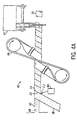
- Figure 4A is a side elevational view of an alternative machine or apparatus for forming the roller cover of Figure 1
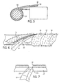
- Figure 5 is a sectional view of the apparatus of Figure 4A.
- Figure 6 is an enlarged fragmentary side elevational view of the apparatus of Figure 4A illustrating the blade securing opposite edges of the material together to form the roller cover of Figure 1 about a mandril.
- Figure 7 is an enlarged side elevational view further illustrating the blade securing opposite edges of the material together to form the roller cover of Figure 1.
- Figure 8 is a sectional view of a first alternative embodiment of the roller cover of Figure 1.
- Figure 9 is a sectional view of a second alternative embodiment of the roller cover of Figure 1.
- Figure 10 is a third alternative embodiment of the roller cover of Figure 1.
- Figures 1-7 illustrate a process of forming a roller cover 10 shown in Figure 1
- a paint carrying medium such as a fabric nap or pile material 12 having a backing 13 that is pre-affixed to thermoplastic core material 14 to form a composite core/fabric material 16 (shown in Figure 2).
- Material 16 is severed to form continuous strips 18.
- fabric material 12 and core material 14 may be pre-cut into strips and then secured to one another prior to winding.
- Strip 18 of material 16 is then wound about mandril 20 as shown in Figures 3 and 4.
- edges 24 are treated to an adhesive state and are positioned in close proximity to one another such that edges 24 of adjacent windings are secured to one another.
- core material 14 comprises a single layer of thermoplastic material.
- a heated pin, knife or blade 22 extends into contact with one or both edges 24 of the thermoplastic core material 14 of adjacent windings to melt the thermoplastic core material 14 such that the windings of strip 18 fuse to one another as it is wound about the mandrel.
- Figures 6 and 7 illustrate heated blade 22 contacting edges 24 of the thermoplastic core material 14 to melt and fuse edges 24 to one another to form a wound tube. Once strip is wound the length of mandrel, the heater element is disengaged and unused composite core/fabric is cut leaving a wound tube. Once the wound tube has cooled, it is cut to desired lengths.
- edges 24 are illustrated as being heated to enable edges 24 to be fused to one another, blade 22 may alternatively be replaced with a dispenser which dispenses an adhesive between adjacent winding edges 24 to adhere the edges 24 to one another.
- the adhesive dispensed between adjacent winding edges 24 is preferably compatible with core material 14 so as to bond adjacent winding edges 24 to one another.
- adhesives include, but are not limited, liquid thermoplastic adhesives such as polypropylene, hot melt, etc. or thermoset adhesives such as epoxy, urethanes, etc. Although less desirable, less solvent resistant adhesives or glues may also be employed.
- Figures 1-7 depict core material 14 as generally comprising a single layer of somewhat rigid material such as polypropylene or polyethylene, core material 14 may alternatively comprise a composite of different materials such as described hereafter in section 5.
- core material 14 may alternatively comprise a composite of different materials such as described hereafter in section 5.
- only one of the multiple layers of core material 114 needs to be thermoplastic material, wherein heated pin, knife or blade 22 extends into contact with edge 24 of the layer to fuse adjacent windings of strip 18 to one another.
- Adjacent layers of the multiple layer composite of core material 14 may be formed from non-thermoplastic materials.
- core material 14 may alternatively be formed from a non-rigid, preferably compressible, material such as described hereinafter in section 2.
- core material 14 is non-rigid and compressible to facilitate better adherence to the roller frame or roller cage.
- roller cover 10 may be formed by spirally wrapping the strips of composite material 16
- roller cover 10 may be formed by folding a generally rectangular panel about a cylindrical mandril and fusing or adhering opposite edges of the rectangular panel to one another to form the generally tubular roller cover.
- Figures 3 and 4 generally depict a batch process in which once strip 18 has been completely wound about the length of mandril 20 with edges 24 being secured to one another either by fusion or by adhesive, the heater element or dispenser element is disengaged and unused material 16 is cut leaving a wound tube that, once sufficiently cooled, is further cut into desired lengths.
- end 19 of strip 18 is secured to mandril 20 and mandril is rotated by rotary actuator 32 as strip 18 is supplied by feeder 28.
- mandril 20 may alternatively be stationary as strip 18 is rotated about the axis of mandril 20.
- roller cover 10 is illustrated in Figures 3 and 4 as being formed from the above-described batch process, core 10 may alternatively be formed continuously.
- Figure 4A depicts an apparatus 40 configured to continuously wind and produce roller covers 10.
- Apparatus 40 generally includes mandril 42, edge treater 44, drive 46 and severing device 47.
- Mandril 42 comprises a conventionally known stationary cylindrical mandril extending from a feeder (not shown), which supplies strip 18 to mandril 42, to severing device 47.
- Edge treater 44 extends adjacent to mandril 42 and comprises a device projecting into close proximity with and between adjacent edges 24 of strips 18. Treater 44 is configured to treat the adjacent edges 24 such that the adjacent edges 24 become secured to one another.
- edge treater 44 includes a heated element such as a knife, blade or pin which melts thermoplastic material of strip 18 to fuse adjacent edges 24 to one another.
- surface treater 44 includes a dispenser configured to dispense a liquid adhesive between adjacent edges 24. Once adjacent edges 24 have been either partially melted and fused to one another or adhered to one another by a liquid adhesive, the partially melted thermoplastic material or the adhesive is allowed to solidify.
- the solidification is enhanced by internally formed cooling or liquid cooling passages 48 that extend through mandril 42.
- various other means may also be used to solidify or set the material depending upon the type of adhesive applied between edges 24, Such alternative means may alternatively include heat, air, or various forms of radiation.
- drive 46 engages an outermost surface of the formed tube to both rotate the formed tube about mandril 42 and to also axially drive the formed tube towards severing device 47.
- drive 46 comprises a conventionally known Ford drive.
- various other drive mechanisms may be employed.
- Severing device 47 comprises a conventionally known saw configured to engage and cut through the tube to form roller covers 10 having a desired length. Because apparatus 40 forms roller covers 10 in a continuous fashion, apparatus 40 does not require production interruptions as does the batch process employed by apparatus 30.
- the above-described processes apply the fabric to the core material before winding the fabric material. Because only the edges of the windings are heated or have an adhesive material applied thereto, shrinkage is reduced resulting in greater dimensional stability and less distortion. Because only the edges need to be heated, rather than the entire surface, the roller covers are produced at a much faster rate. Because the fabric and the core material are simultaneously wound and simultaneously cut, manufacturing through-put time is reduced. In addition, inventory levels are also reduced. Moreover, the number of manufacturing steps and the number and costs of manufacturing equipment is lessened. Because only edges 24 are secured to one another, less process control is required. Furthermore, because the fabric material is pre-secured to the core material, previously required alignment of plys is no longer necessary, In addition, the amount of equipment required to produce such a roller cover is reduced.
- Figure 8 depicts an alternative roller cover 50 formed by the above-described process or alternatively formed by conventional processes in which the core 52 is first formed and then the paint carrying medium, such as fabric 54, is applied to the core 52.
- the non-rigid core is advantageous in that it is substantially compressible so as to better adhere to the roller cage.
- the non-rigid core is preferably formed from a thermoplastic elastomeric material or from a thermoplastic foamed material. Because a foam material generally has a greater thickness has more surface texture and has more gripping, the core including the foam material has a greater outer diameter, increasing the carrying capacity at which paint or other liquids may be applied to a surface while maintaining a standard internal diameter to fit onto industry standard size frames.
- the fabric backing 13 is formed from a thermoplastic material and is heated to a temperature above its melting point. While above its melting point, the fabric backing is applied to a core 14 having a thermoplastic outer surface.
- the fabric is secured by flame bonding or adhesive, etc, to a foam which serves as a backing. Only the exposed surface of the foam is heated to a point above its melting point while rest of backing and fabric remains below the melt temperature. The foam backing is then applied to a thermoplastic core to fuse the two together.
- a suitable adhesive such as melted or liquid thermoplastic material (Propylene, ethylene, hot melt or thermoset material, etc.) may be applied to fabric backing 13 with the fabric backing 13 then being positioned against core 14 until the backing becomes bonded to core 14.
- melted or liquid thermoplastic material Propylene, ethylene, hot melt or thermoset material, etc.
- both surfaces, backing and core can be heated or have the adhesive applied to them prior to coming in contact.
- a relatively thick solid or foamed, single layer or multiple layer, fabric backing is formed into strips and is then wrapped about a mandril.
- a hot knife or blade is positioned between the strip edges to heat the edges of the fabric backing to a temperature above its melting point so as to fuse the edges together.
- the fabric backing serves as a core.
- an adhesive material may be deposited between edger 24 of consecutive strip wraps and then brought together to secure the fabric backing strips to one another.
- These products/processes may include one or more layers of material to build up the backing/base material.
- fabric backing yarns are fairly thin, however, as fabric backing yarns or back coating compounds applied to the fabric backing yarns are increased sufficiently in thickness to act like the composite base, then products made from the above processes can be made directly from strips of fabric. While there is a wide range of material selection for the backing/base materials, products made from this process can be tuned to specific applications, While not all of the material combinations are listed here, one skilled in the art can select different materials for selected applications,
- Figure 9 illustrates a roller cover 110 having a core 112 and a fabric 113 affixed thereto by either a conventional process or one of the processes described above.
- Core 112 is formed from multiple layers fused or otherwise secured to one another to provide optimum paint roller characteristics
- core 112 includes layers 118, 120.
- Layers 118, 120 may be formed from different materials or may be formed from substantially the same materials with slightly modified compositions so as to provide desirable characteristics.
- layers 118 and 120 may preferably vary from one another so as to have different characteristics with respect to resiliency, coefficient of friction or gripping, rigidity, solvent resistance, color, bondability, fusing characteristics such as melt point, curing characteristics, thermal conductivity and liquid barrier characteristics.
- roller covers 110 optimally address the many different requirements for roller covers 110 in various applications.
- layer 118 comprises a phenolic paper while layer 120 comprises a thermoplastic or thermoset material resistant to solvents.
- Layer 118 enables core 112 to be better gripped by the roller cage to prevent slippage.
- Layer 120 prevents layer 118 from breaking up when exposed to harsh solvents and maintains a shape of roller cover 110.
- layer 118 is formed from polyethylene while layer 120 is formed from polypropylene. Because layer 118 is formed from polyethylene, layer 118 is better gripped by the roller frame cage while layer 120 provides improved core flexibility to mate up with frame. This alternative embodiment also enables core 112 to be formed from materials having multiple colors for aesthetic reasons and for product source identifying purposes.
- FIG 10 illustrates yet another roller cover 210, an alternative embodiment of roller cover 110 shown in Figure 9.
- Roller cover 210 is identical to roller cover 110 except that layers 118 and 120 are replaced with layers 218 and 220 which comprise relatively thin layers of a solvent resistant material such as thermosets (urethanes, epoxies) or thermoplastics (polyethylenes, polyprophylenes).
- Layers 218 and 220 have an intermediate stiffening layer 222 disposed therebetween.
- Stiffening layer 222 rigidifies the composite core 112 and enables layers 218 and 220 to have a greatly reduced thickness.
- layers 218 and 220 need merely have a sufficient thickness so as to serve as a solvent barrier protecting the less expensive and less solvent resistant stiffening layer disposed therebetween from contact with solvents and from degradation.
- layers 218 and 220 are fused or adhesively bonded to one another so as to encapsulate intermediate layer 222.
- layer 220 is fused to fabric 113.
- layer 220 also has a minimum sufficient thickness that enables layer 220 to be melted and fused with the backing of fabric 113.
- intermediate layer 222 comprises a metal such as a foil or a conventionally known phenolic paper.
- layers 218, 220 and 222 continuously extend about the axis of roller cover 210 so as to be generally tubular and imperforate in nature.
- intermediate layer 222 may include circumferential or axial gaps along the length of core 212, whereby either or both of layers 218 and 220 fill such gaps or whereby such gaps are unfilled,
- layers 218 and 220 may also include circumferential or axial gaps at various locations along the length of roller cover 210.
- roller cover 210 is illustrated as including a core 212 having an intermediate layer sandwiched between two outer layers, core 212 may alternatively include greater than three layers and may include three layers wherein each layer is formed from a different material or a material having different compositions and characteristics.
Landscapes
- Engineering & Computer Science (AREA)
- Mechanical Engineering (AREA)
- Rolls And Other Rotary Bodies (AREA)
- Coating Apparatus (AREA)
- Delivering By Means Of Belts And Rollers (AREA)
Applications Claiming Priority (2)
| Application Number | Priority Date | Filing Date | Title |
|---|---|---|---|
| US17732800P | 2000-01-21 | 2000-01-21 | |
| US177328P | 2000-01-21 |
Publications (2)
| Publication Number | Publication Date |
|---|---|
| EP1118450A2 true EP1118450A2 (fr) | 2001-07-25 |
| EP1118450A3 EP1118450A3 (fr) | 2001-11-07 |
Family
ID=22648177
Family Applications (1)
| Application Number | Title | Priority Date | Filing Date |
|---|---|---|---|
| EP01101139A Withdrawn EP1118450A3 (fr) | 2000-01-21 | 2001-01-22 | Applicateur de peinture et son procédé de fabrication |
Country Status (3)
| Country | Link |
|---|---|
| US (1) | US6615490B2 (fr) |
| EP (1) | EP1118450A3 (fr) |
| CA (1) | CA2331839A1 (fr) |
Cited By (5)
| Publication number | Priority date | Publication date | Assignee | Title |
|---|---|---|---|---|
| CN102459046A (zh) * | 2009-04-29 | 2012-05-16 | 钱德拉·塞卡 | 制造滚漆筒及其部件的方法 |
| WO2012118379A1 (fr) * | 2011-03-03 | 2012-09-07 | Airborne International B.V. | Procédé et appareil de fabrication d'un tuyau composite continu |
| CN105171362A (zh) * | 2015-11-02 | 2015-12-23 | 宝钢轧辊科技有限责任公司 | 森吉米尔中间辊的制造方法 |
| US9862135B2 (en) | 2010-06-08 | 2018-01-09 | Airborne International B.V. | Method and device for manufacturing composite products comprising a planar portion |
| WO2020174210A1 (fr) * | 2019-02-26 | 2020-09-03 | Ridgway Machines Ltd | Procédé de fabrication de tuyaux renforcés |
Families Citing this family (24)
| Publication number | Priority date | Publication date | Assignee | Title |
|---|---|---|---|---|
| US6539999B2 (en) * | 2001-02-19 | 2003-04-01 | Newell Operating Company | Apparatus and method for making variable paint roller covers |
| US7503190B1 (en) | 2007-10-12 | 2009-03-17 | Seamless Technologies, Llc | Forming a tubular knit fabric for a paint roller cover |
| DE10318680B4 (de) * | 2003-04-24 | 2006-06-14 | Gregor Kohlruss | Überzug aus Webplüsch |
| JP4445239B2 (ja) * | 2003-10-16 | 2010-04-07 | 株式会社クラレ | ペイントローラー |
| US20050188484A1 (en) * | 2004-02-19 | 2005-09-01 | Lytle Clifton E. | Quick change roller replacement |
| US8167782B2 (en) * | 2007-02-16 | 2012-05-01 | Linzer Products Corp. | Method and apparatus for making a paint roller and product produced thereby |
| US8182645B2 (en) * | 2008-01-17 | 2012-05-22 | Seamless Technologies, Llc | Methods of manufacturing paint roller covers from a tubular fabric sleeve |
| US8298364B2 (en) * | 2008-01-17 | 2012-10-30 | Seamless Technologies, Llc | Methods of manufacturing paint roller covers from a tubular fabric sleeve |
| US8118967B2 (en) * | 2008-01-17 | 2012-02-21 | Seamless Technologies, Llc | Methods of manufacturing paint roller covers from a tubular fabric sleeve |
| US8221578B2 (en) | 2007-04-25 | 2012-07-17 | Seamless Technologies, Llc | Methods of manufacturing paint roller covers from a tubular fabric sleeve |
| US8858750B2 (en) | 2007-04-25 | 2014-10-14 | Seamless Technologies, Llc | Methods of manufacturing paint roller covers from a tubular fabric sleeve |
| US8882957B2 (en) | 2007-04-25 | 2014-11-11 | Seamless Technologies, Llc | Methods of manufacturing paint roller covers from a tubular fabric sleeve |
| US7905980B2 (en) * | 2007-04-25 | 2011-03-15 | Seamless Technologies, Llc | Method of manufacturing paint roller covers from a tubular fabric sleeve |
| US7503191B2 (en) | 2007-04-25 | 2009-03-17 | Seamless Technologies, Llc | Tubular sliver knit fabric for paint roller covers |
| US7748241B2 (en) * | 2007-04-25 | 2010-07-06 | Seamless Technologies, Llc | Tubular cut pile knit fabric for paint roller covers |
| US7596972B2 (en) * | 2007-04-25 | 2009-10-06 | Seamless Technologies, Llc | Tubular knit fabric having alternating courses of sliver fiber pile and cut-pile for paint roller covers |
| US7552602B2 (en) * | 2007-10-12 | 2009-06-30 | Seamless Technologies, Llc | Forming a tubular knit fabric for a paint roller cover |
| US20090191390A1 (en) * | 2008-01-25 | 2009-07-30 | Linzer Products Corp. | Paint roller having reinforcement layers and method for assembling the paint roller |
| US20100282400A1 (en) * | 2009-05-05 | 2010-11-11 | Chandra Sekar | Methods for manufacturing a paint roller and component parts thereof |
| US8142599B2 (en) * | 2009-01-08 | 2012-03-27 | Chandra Sekar | Methods for manufacturing a paint roller and component parts thereof |
| US8142587B2 (en) * | 2009-05-05 | 2012-03-27 | Chandra Sekar | Methods for manufacturing a paint roller and component parts thereof |
| US9272304B1 (en) | 2012-06-11 | 2016-03-01 | Leith Seanan Emery | Paint edger devices |
| US20150238061A1 (en) * | 2014-02-21 | 2015-08-27 | The Scott Fetzer Company | Rotary head, method and system for use with hard and soft surfaces |
| US20190105682A1 (en) * | 2017-10-05 | 2019-04-11 | Nova Wildcat Shur-Line, Llc | Roller cover core and method of manufacture |
Family Cites Families (72)
| Publication number | Priority date | Publication date | Assignee | Title |
|---|---|---|---|---|
| US3126306A (en) | 1964-03-24 | Attoxj | ||
| US1944970A (en) | 1933-07-29 | 1934-01-30 | Otto W Dieffenbach | Continuous method of making sheet cellulose tubes |
| US2708763A (en) | 1950-08-16 | 1955-05-24 | George W Jacoby | Paint roller having porous facing thereover |
| FR1059649A (fr) | 1952-07-10 | 1954-03-26 | Rouleau pour peintre | |
| US2891301A (en) | 1952-08-26 | 1959-06-23 | Wooster Brush Co | Paint applicator |
| US2823402A (en) | 1954-10-04 | 1958-02-18 | Leonard H Phillips | Roller-type applicators |
| US3010867A (en) * | 1955-10-20 | 1961-11-28 | Seamless Covers Inc | Manufacture of paint rollers |
| US2959800A (en) | 1958-07-02 | 1960-11-15 | Edward S Bischoff | Snap-on brush |
| US3280516A (en) | 1964-06-09 | 1966-10-25 | Tennant Co G H | Abrasive roll |
| US3366719A (en) | 1964-08-21 | 1968-01-30 | Armstrong Cork Co | Method and apparatus for continuously producing tubing |
| US3607492A (en) * | 1965-05-20 | 1971-09-21 | Ici Australia Ltd | Process for preparing composite tube |
| US3457130A (en) | 1966-07-11 | 1969-07-22 | Owens Illinois Inc | Method and apparatus for forming a tubular article of wound plies of thermoplastic strip material |
| US3524779A (en) | 1966-08-31 | 1970-08-18 | American Can Co | Method of making wound tubular products |
| US3428239A (en) | 1966-10-07 | 1969-02-18 | Int Paper Co | Spiral wound can for packaging beverages under substantial pressure |
| US3394423A (en) | 1966-11-21 | 1968-07-30 | Edward S. Bischoff | Flexible paint roller |
| US3494989A (en) | 1968-05-31 | 1970-02-10 | Baxter Laboratories Inc | Method for producing plastic article |
| US3555976A (en) | 1969-01-14 | 1971-01-19 | Int Paper Co | Method and apparatus for producing spiral wound container |
| DE1928269A1 (de) | 1969-06-03 | 1970-12-10 | Puetzer Kunststofftechnik Gmbh | Verfahren zur Herstellung von Stuetzelementen aus verstaerktem chemischen Werkstoff und nach dem Verfahren hergestelltes Stuetzelement |
| US3620869A (en) | 1969-07-16 | 1971-11-16 | Clevepak Corp | Method of making tubes |
| CA921410A (en) | 1970-04-16 | 1973-02-20 | Hielema Ralph | Pipe coating |
| US4010054A (en) | 1971-05-03 | 1977-03-01 | Albert L. Jeffers | Thermoplastic filament winding process |
| US3774278A (en) | 1972-02-07 | 1973-11-27 | Ideal Brushes Inc | Paint roller and frame |
| US3763532A (en) | 1972-06-05 | 1973-10-09 | Dayco Corp | Drafting roller construction |
| US3886622A (en) | 1973-01-26 | 1975-06-03 | Western Sales & Supply Co | Tubular buffer element |
| US4078957A (en) | 1973-10-03 | 1978-03-14 | Bradt Rexford H | Filament winding apparatus and method |
| US3886621A (en) | 1974-01-22 | 1975-06-03 | Homer Ernest Welsh | Paint roller and handle therefor |
| ZA75470B (en) | 1974-06-24 | 1976-01-28 | J Dukees | Process and apparatus for the manufacture of plastic sandwich elements |
| US3877123A (en) | 1974-09-04 | 1975-04-15 | Painter Corp E Z | Paint roller core |
| GB1555632A (en) | 1977-03-25 | 1979-11-14 | Winn & Coales Denso Ltd | Hot applied pipe coatings |
| US4191792A (en) | 1978-10-30 | 1980-03-04 | Padco, Inc. | Paint roller |
| US4385480A (en) | 1979-09-04 | 1983-05-31 | Burchette Jr Robert L | Apparatus for wrapping or producing cylindrical articles and method for same |
| US4403384A (en) | 1980-06-05 | 1983-09-13 | Champion International Corporation | Applicator for direct roll coating |
| US4361923A (en) | 1981-08-06 | 1982-12-07 | Helmac Products Corporation | Lint remover |
| CA1222115A (fr) | 1984-06-22 | 1987-05-26 | Hans Hede | Fabrication de produits composites |
| JPS6115816A (ja) | 1984-06-30 | 1986-01-23 | Lion Corp | 頭髪化粧料 |
| US5137595A (en) | 1985-01-11 | 1992-08-11 | Newell Co. | Paint roller manufacturing apparatus |
| ES283921Y (es) | 1985-01-11 | 1986-06-16 | Alvarez Garcia Jaime | Dispositivo perfeccionado de enrollamiento helicoidal de cinta de tejido sobre tubos de plastico para rodillos de pintura |
| US4627127A (en) | 1985-02-13 | 1986-12-09 | Minnesota Mining And Manufacturing Company | Cylindrical brush |
| DE3616114A1 (de) | 1986-05-13 | 1987-11-19 | Arthur Schneider | Geraet zum auftragen von farben und fluessigkeiten gleichzeitig auf mehreren ebenen |
| DE8700258U1 (de) | 1987-01-07 | 1988-05-05 | Irbit Research + Consulting Ag, Freiburg/Fribourg | Transportwalze |
| US5160674A (en) | 1987-07-29 | 1992-11-03 | Massachusetts Institute Of Technology | Microcellular foams of semi-crystaline polymeric materials |
| US4937141A (en) | 1987-08-03 | 1990-06-26 | Newell Operating Company | Microcellular synthetic paintbrush bristles |
| US5022112A (en) | 1987-08-03 | 1991-06-11 | Newell Operating Company | Paint brush with microcellular synthetic bristles |
| US5032456A (en) | 1987-09-11 | 1991-07-16 | Newell Operating Company | Microcellular synthetic paintbrush bristles |
| FR2622506B1 (fr) | 1987-11-03 | 1990-04-13 | Aerospatiale | Procede et machine de fabrication de pieces tubulaires a partir d'au moins une bande de matiere souple, et pieces tubulaires ainsi obtenues |
| US4878976A (en) * | 1987-12-17 | 1989-11-07 | Toyo Chemical Co., Ltd. | Method for continuously manufacturing synthetic resin tube |
| DE3903519C2 (de) | 1989-02-07 | 1994-01-20 | Farbrollerfabrik Fries & Co Kg | Farbroller |
| US5273604A (en) * | 1990-03-06 | 1993-12-28 | Ez Paintr Corporation | Method and apparatus for manufacturing paint roller and product produced thereby |
| US5397414A (en) * | 1989-03-07 | 1995-03-14 | Ez Painter Corporation | Method and apparatus for manufacturing paint roller and product produced thereby |
| US5195242A (en) | 1989-08-15 | 1993-03-23 | Chandra Sekar | Method of making a paint roller |
| US20020066521A1 (en) * | 1989-08-15 | 2002-06-06 | Chandra Sekar And Pinnacle Partners, Inc. | Method of making a paint roller |
| US5090084A (en) | 1989-08-30 | 1992-02-25 | Cleanline Corporation | Cleaning roller for surfaces and apparatus for use therewith |
| US5146646A (en) | 1990-02-20 | 1992-09-15 | Minnesota Mining And Manufacturing Company | Paint applicator |
| US6203648B1 (en) * | 1990-03-06 | 2001-03-20 | Newell Operating Company | Method for manufacturing paint roller |
| US5206968A (en) | 1991-01-09 | 1993-05-04 | Ez Paintr Corporation | Paint roller |
| US5158986A (en) | 1991-04-05 | 1992-10-27 | Massachusetts Institute Of Technology | Microcellular thermoplastic foamed with supercritical fluid |
| US5106356A (en) | 1991-05-30 | 1992-04-21 | Sonoco Products Company | Method and apparatus for the manufacture of paperboard tubes having controlled outside diameter |
| CA2075575C (fr) | 1991-11-29 | 2004-04-20 | Howard Graves | Cadre et cage pour rouleaux a peinture |
| ES2148233T3 (es) | 1992-11-09 | 2000-10-16 | American Roller Co | Rodillo de carga con capa de ceramicas mezcladas. |
| JPH06332334A (ja) | 1993-05-18 | 1994-12-02 | Japan Gore Tex Inc | 定着用弾性ロール |
| US5468207A (en) | 1993-06-14 | 1995-11-21 | Newell Operating Company | Method and apparatus of manufacturing a paint roller |
| US5866053A (en) | 1993-11-04 | 1999-02-02 | Massachusetts Institute Of Technology | Method for providing continuous processing of microcellular and supermicrocellular foamed materials |
| US5471703A (en) | 1994-05-16 | 1995-12-05 | Home E Z Products, Inc. | Apparatus for applying paint |
| US5619769A (en) | 1994-12-01 | 1997-04-15 | Hutt; Heinz | Paint roller bearing support assembly |
| US5613265A (en) | 1995-02-06 | 1997-03-25 | Gemmell; Wayne | Paint roller assembly |
| US5862591A (en) | 1996-04-25 | 1999-01-26 | Kulkaski; Stanley V. | Method for manufacturing paint rollers |
| JPH10218418A (ja) | 1997-02-14 | 1998-08-18 | Noritsu Koki Co Ltd | 搬送用ローラおよびその製造方法 |
| DE19719559A1 (de) * | 1997-05-09 | 1998-11-12 | Koenig & Bauer Albert Ag | Verfahren und Vorrichtung zur Montage biegsamer Druckplatten |
| JP2952224B2 (ja) | 1997-12-03 | 1999-09-20 | 吉川工業株式会社 | 被印刷体圧着・移送用ローラー |
| US6145196A (en) | 1998-03-03 | 2000-11-14 | Ripstein; Jorge | Method of making a paint roller with non-plastic base material |
| US6175985B1 (en) * | 1998-11-04 | 2001-01-23 | E. I. Du Pont De Nemours & Company | Paint roller and method of making same using continuous yarn tuftstrings |
| US6159134A (en) * | 1999-05-04 | 2000-12-12 | Sekar; Chandra | Methods for manufacturing a paint roller with integrated core and cover |
-
2001
- 2001-01-19 US US09/766,110 patent/US6615490B2/en not_active Expired - Lifetime
- 2001-01-22 CA CA002331839A patent/CA2331839A1/fr not_active Abandoned
- 2001-01-22 EP EP01101139A patent/EP1118450A3/fr not_active Withdrawn
Non-Patent Citations (1)
| Title |
|---|
| None |
Cited By (10)
| Publication number | Priority date | Publication date | Assignee | Title |
|---|---|---|---|---|
| CN102459046A (zh) * | 2009-04-29 | 2012-05-16 | 钱德拉·塞卡 | 制造滚漆筒及其部件的方法 |
| EP2424800A4 (fr) * | 2009-04-29 | 2012-12-19 | Chandra Sekar | Procédés de fabrication d'un rouleau de peinture et de ses composants |
| CN102459046B (zh) * | 2009-04-29 | 2015-05-20 | 钱德拉·塞卡 | 制造滚漆筒及其部件的方法 |
| US9862135B2 (en) | 2010-06-08 | 2018-01-09 | Airborne International B.V. | Method and device for manufacturing composite products comprising a planar portion |
| WO2012118379A1 (fr) * | 2011-03-03 | 2012-09-07 | Airborne International B.V. | Procédé et appareil de fabrication d'un tuyau composite continu |
| US10144171B2 (en) | 2011-03-03 | 2018-12-04 | AO & G Hollding B.V. | Method for manufacturing continuous composite tube, apparatus for manufacturing continuous composite tube |
| US10226892B2 (en) | 2011-03-03 | 2019-03-12 | Ao&G Holding B.V. | Method for manufacturing continuous composite tube, apparatus for manufacturing continuous composite tube |
| CN105171362A (zh) * | 2015-11-02 | 2015-12-23 | 宝钢轧辊科技有限责任公司 | 森吉米尔中间辊的制造方法 |
| WO2020174210A1 (fr) * | 2019-02-26 | 2020-09-03 | Ridgway Machines Ltd | Procédé de fabrication de tuyaux renforcés |
| US12023851B2 (en) | 2019-02-26 | 2024-07-02 | Ridgway Machines Ltd | Method of manufacturing reinforced pipe |
Also Published As
| Publication number | Publication date |
|---|---|
| CA2331839A1 (fr) | 2001-07-21 |
| EP1118450A3 (fr) | 2001-11-07 |
| US20010045014A1 (en) | 2001-11-29 |
| US6615490B2 (en) | 2003-09-09 |
Similar Documents
| Publication | Publication Date | Title |
|---|---|---|
| US6615490B2 (en) | Method of manufacture of paint application | |
| EP1232849B1 (fr) | Procédé et appareil de fabrication de divers rouleaux à peinture | |
| US6159134A (en) | Methods for manufacturing a paint roller with integrated core and cover | |
| CA2153139C (fr) | Procede de fabrication de rouleaux a peinturer | |
| EP2324989B1 (fr) | Procédé de fabrication d'un rouleau de peinture stratifié | |
| JPH0815579B2 (ja) | ペンキローラー及びペンキローラーを製造するための方法と装置 | |
| US7007887B2 (en) | Tubular core with polymer plies | |
| US7846283B2 (en) | Methods for manufacturing a paint roller with perforated substrate | |
| MX2008012878A (es) | Nucleos para cinta adhesiva a sensible a presion, y metodos para elaborar los mismos. | |
| CA1088881A (fr) | Lamine tubulaire servant d'emballage pliable, et procede de fabrication | |
| CA2315283C (fr) | Methode de fabrication de rouleaux a peinture avec un materiau de base non en plastique | |
| JP4005316B2 (ja) | 梱包用バンドコイルの型崩れ防止方法 | |
| US20090320994A1 (en) | Methods for manufacturing a paint roller with perforated substrate | |
| CN101626882A (zh) | 用于制造涂料滚筒的方法和装置及由此制成的产品 | |
| JPS6348784B2 (fr) | ||
| JP3037179U (ja) | 透明フィルム外装被覆層を有する容器用紙筒 | |
| JPS60213651A (ja) | 貼付加工用シ−ト部材 | |
| JP3776495B2 (ja) | 紙製品の切断紙粉発生防止方法 | |
| CA1153321B (fr) | Tube lamelle pour contenants ecrasables, et methode de fabrication connexe | |
| JPS6153027A (ja) | 積層チユ−ブの製造法 | |
| JPH0124701B2 (fr) | ||
| JP2001010768A (ja) | 梱包用バンドコイルおよびその製造方法 | |
| HK1158571B (en) | Method for making a laminated paint roller | |
| AU7204400A (en) | Method of making a paint roller | |
| JPH07314260A (ja) | 切削方式による金属繊維の製造法 |
Legal Events
| Date | Code | Title | Description |
|---|---|---|---|
| PUAI | Public reference made under article 153(3) epc to a published international application that has entered the european phase |
Free format text: ORIGINAL CODE: 0009012 |
|
| AK | Designated contracting states |
Kind code of ref document: A2 Designated state(s): DE FR GB Kind code of ref document: A2 Designated state(s): AT BE CH CY DE DK ES FI FR GB GR IE IT LI LU MC NL PT SE TR |
|
| AX | Request for extension of the european patent |
Free format text: AL;LT;LV;MK;RO;SI |
|
| PUAL | Search report despatched |
Free format text: ORIGINAL CODE: 0009013 |
|
| AK | Designated contracting states |
Kind code of ref document: A3 Designated state(s): AT BE CH CY DE DK ES FI FR GB GR IE IT LI LU MC NL PT SE TR |
|
| AX | Request for extension of the european patent |
Free format text: AL;LT;LV;MK;RO;SI |
|
| 17P | Request for examination filed |
Effective date: 20020506 |
|
| AKX | Designation fees paid |
Free format text: DE FR GB |
|
| STAA | Information on the status of an ep patent application or granted ep patent |
Free format text: STATUS: THE APPLICATION IS DEEMED TO BE WITHDRAWN |
|
| 18D | Application deemed to be withdrawn |
Effective date: 20030801 |