EP1118497A2 - Sitzplatte für einen Fahrzeugsitz - Google Patents
Sitzplatte für einen Fahrzeugsitz Download PDFInfo
- Publication number
- EP1118497A2 EP1118497A2 EP00126562A EP00126562A EP1118497A2 EP 1118497 A2 EP1118497 A2 EP 1118497A2 EP 00126562 A EP00126562 A EP 00126562A EP 00126562 A EP00126562 A EP 00126562A EP 1118497 A2 EP1118497 A2 EP 1118497A2
- Authority
- EP
- European Patent Office
- Prior art keywords
- plate
- seat
- seat plate
- areas
- plate areas
- Prior art date
- Legal status (The legal status is an assumption and is not a legal conclusion. Google has not performed a legal analysis and makes no representation as to the accuracy of the status listed.)
- Granted
Links
- 238000005452 bending Methods 0.000 claims abstract description 4
Images
Classifications
-
- B—PERFORMING OPERATIONS; TRANSPORTING
- B60—VEHICLES IN GENERAL
- B60N—SEATS SPECIALLY ADAPTED FOR VEHICLES; VEHICLE PASSENGER ACCOMMODATION NOT OTHERWISE PROVIDED FOR
- B60N2/00—Seats specially adapted for vehicles; Arrangement or mounting of seats in vehicles
- B60N2/02—Seats specially adapted for vehicles; Arrangement or mounting of seats in vehicles the seat or part thereof being movable, e.g. adjustable
- B60N2/04—Seats specially adapted for vehicles; Arrangement or mounting of seats in vehicles the seat or part thereof being movable, e.g. adjustable the whole seat being movable
- B60N2/16—Seats specially adapted for vehicles; Arrangement or mounting of seats in vehicles the seat or part thereof being movable, e.g. adjustable the whole seat being movable height-adjustable
- B60N2/18—Seats specially adapted for vehicles; Arrangement or mounting of seats in vehicles the seat or part thereof being movable, e.g. adjustable the whole seat being movable height-adjustable the front or the rear portion of the seat being adjustable, e.g. independently of each other
- B60N2/1807—Seats specially adapted for vehicles; Arrangement or mounting of seats in vehicles the seat or part thereof being movable, e.g. adjustable the whole seat being movable height-adjustable the front or the rear portion of the seat being adjustable, e.g. independently of each other characterised by the cinematic
- B60N2/1842—Seats specially adapted for vehicles; Arrangement or mounting of seats in vehicles the seat or part thereof being movable, e.g. adjustable the whole seat being movable height-adjustable the front or the rear portion of the seat being adjustable, e.g. independently of each other characterised by the cinematic pivoting about an axis located in the rear
Definitions
- the invention relates to a seat plate according to the preamble of claim 1.
- a seat plate of this structure known from DE 35 32 608 A1 consists of two separate plate areas, one of which, namely the one in the front, by one transverse axis provided at its rear end by one of it overlapped tilt adjustment device is pivotable. This makes it possible to get one the front part of the seat relative to the rest of the same in height.
- the rear area of the seat plate takes no part in the adjustment movements, so that depending on the setting of the front area of the seat plate in the immediate vicinity of the facing ends of the two plate areas a more or less sharp kink results. In the prior art, this is done by Subdivision of the seat cushion above the seat plate at this point considered.
- the invention has for its object to provide a generic seat plate not one without affecting the desired adjustment option has a simpler structure, but also simplifies the overall structure of the seat and avoids high local loads.
- the invention thus enables the one-piece design of the seat plate without the relative pivotability of the different plate areas must be dispensed with. Complicated hinge arrangements are unnecessary because the relative pivotability of the adjoining plate areas solely through suitably profiled zones of the Seat plate itself is guaranteed. These zones are so profiled that the Bending resistance of the seat plate is reduced.
- the one-piece seat plate offers the advantageous Possibility of additional devices, such as weight sensors and fans, via the to provide the entire seat.
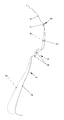
- the seat plate generally designated 1 contains three pivotable relative to one another Plate areas 2, 3 and 4. Area 4 is on a vehicle frame, for example screwed on.
- the front plate area 2 is supported on a known one Tilt adjustment device, for example of the type mentioned in the introduction Disclosure known device. This makes it possible for the two Plate areas 2 and 3, for example, in higher positions 2 'and 3' relative to that rearmost area 4 to pivot, which means almost the entire length the seat plate 1 extending change in the inclination of the seat is achieved.
- This Seat is formed by a cushion (not shown) on the seat plate 1.
- Zones 5 can be seen between the adjoining plate areas 2, 3 and 4 and 6 reduced bending resistance in the drawing plane. These zones are formed by a transverse trough-shaped profile 7 in the case of zone 6 and one Variety of channel-shaped profiles 8 in the case of zone 5; these channel-like profiles 8 In their entirety, as the figure shows, form a meandering cross-sectional profile that stresses occurring during the pivoting over a relatively large Length range of the seat plate 1 and thus distributed over the entire seat.
- the invention not only offers the advantage of reducing stresses in the Seat, but also increases seating comfort, as the inclination adjustment via a greater length range of the seat takes place.
Landscapes
- Engineering & Computer Science (AREA)
- Aviation & Aerospace Engineering (AREA)
- Transportation (AREA)
- Mechanical Engineering (AREA)
- Chair Legs, Seat Parts, And Backrests (AREA)
- Seats For Vehicles (AREA)
- Laminated Bodies (AREA)
- Chairs For Special Purposes, Such As Reclining Chairs (AREA)
Abstract
Description
Claims (3)
- Sitzplatte für einen Fahrzeugsitz, die ein Sitzpolster trägt und zumindest zwei relativ zueinander schwenkbare Plattenbereiche enthält, von denen einer auf einer Neigungsverstellvorrichtung abgestüzt ist, dadurch gekennzeichnet, daß die Plattenbereiche (2, 3, 4) zu einer einteiligen Sitzplatte (1) zusammengefaßt sind, die zwischen den Plattenbereichen (2, 3, 4) zumindest eine durch Profilierung gewonnene Zone (5, 6) verringerten Biegewiderstands enthält.
- Sitzplatte nach Anspruch 1, dadurch gekennzeichnet, daß die Profilierung sich senkrecht zur Schwenkebene erstreckende Rinnen (7, 8) enthält.
- Sitzplatte nach Anspruch 2, dadurch gekennzeichnet, daß die Rinnen (8) senkrecht zu ihrer Erstreckung ein mäanderartiges Querschnittsprofil bilden.
Applications Claiming Priority (2)
| Application Number | Priority Date | Filing Date | Title |
|---|---|---|---|
| DE10001445 | 2000-01-15 | ||
| DE10001445A DE10001445B4 (de) | 2000-01-15 | 2000-01-15 | Sitzplatte für einen Fahrzeugsitz |
Publications (3)
| Publication Number | Publication Date |
|---|---|
| EP1118497A2 true EP1118497A2 (de) | 2001-07-25 |
| EP1118497A3 EP1118497A3 (de) | 2002-02-13 |
| EP1118497B1 EP1118497B1 (de) | 2004-05-19 |
Family
ID=7627585
Family Applications (1)
| Application Number | Title | Priority Date | Filing Date |
|---|---|---|---|
| EP00126562A Expired - Lifetime EP1118497B1 (de) | 2000-01-15 | 2000-12-12 | Sitzplatte für einen Fahrzeugsitz |
Country Status (3)
| Country | Link |
|---|---|
| EP (1) | EP1118497B1 (de) |
| AT (1) | ATE267097T1 (de) |
| DE (2) | DE10001445B4 (de) |
Families Citing this family (2)
| Publication number | Priority date | Publication date | Assignee | Title |
|---|---|---|---|---|
| DE10304570B4 (de) * | 2003-02-05 | 2012-10-18 | Volkswagen Ag | Fahrersitz mit Gewichtssensorik |
| DE102017008153B4 (de) | 2017-08-28 | 2023-03-16 | Audi Ag | Rückenlehne und Sitzvorrichtung |
Citations (1)
| Publication number | Priority date | Publication date | Assignee | Title |
|---|---|---|---|---|
| DE3532608A1 (de) | 1985-09-12 | 1987-03-19 | Grammer Sitzsysteme Gmbh | Sitz mit einem verstellbaren sitzflaechenelement |
Family Cites Families (8)
| Publication number | Priority date | Publication date | Assignee | Title |
|---|---|---|---|---|
| DE1654400B2 (de) * | 1967-10-11 | 1977-01-20 | Ignaz vogel GmbH und Co KG - Fahrzeugsitz 7500 Karlsruhe | Sitzschale |
| JPS5588713A (en) * | 1978-12-27 | 1980-07-04 | Tachikawa Spring Co | Sheet for car in synthetic resin |
| ATE94038T1 (de) * | 1992-01-20 | 1993-09-15 | Stoll Kg Christof | Rueckenlehne fuer einen buerostuhl. |
| JPH0737616Y2 (ja) * | 1992-12-25 | 1995-08-30 | パラマウントベッド株式会社 | ベッドにおけるボトム構造 |
| WO1998008705A1 (en) * | 1996-08-29 | 1998-03-05 | Lear Corporation | Vehicle seat assembly |
| DE19711944C2 (de) * | 1997-03-21 | 2000-08-31 | Girsberger Holding Ag Buetzber | Fahrzeugsitz |
| DE19828254C2 (de) * | 1998-06-25 | 2000-07-20 | Daimler Chrysler Ag | Sitz- und/oder Liegevorrichtung, insbesondere Fahr- oder Flugzeugsitz |
| DE19839322C2 (de) * | 1998-08-28 | 2002-02-28 | Vogel Ind Gmbh | Fahrgastsitz mit Rückenlehne mit länglichen Vertiefungen |
-
2000
- 2000-01-15 DE DE10001445A patent/DE10001445B4/de not_active Expired - Fee Related
- 2000-12-12 EP EP00126562A patent/EP1118497B1/de not_active Expired - Lifetime
- 2000-12-12 AT AT00126562T patent/ATE267097T1/de not_active IP Right Cessation
- 2000-12-12 DE DE50006480T patent/DE50006480D1/de not_active Expired - Lifetime
Patent Citations (1)
| Publication number | Priority date | Publication date | Assignee | Title |
|---|---|---|---|---|
| DE3532608A1 (de) | 1985-09-12 | 1987-03-19 | Grammer Sitzsysteme Gmbh | Sitz mit einem verstellbaren sitzflaechenelement |
Also Published As
| Publication number | Publication date |
|---|---|
| DE50006480D1 (de) | 2004-06-24 |
| DE10001445B4 (de) | 2007-12-27 |
| EP1118497B1 (de) | 2004-05-19 |
| DE10001445A1 (de) | 2001-07-19 |
| ATE267097T1 (de) | 2004-06-15 |
| EP1118497A3 (de) | 2002-02-13 |
Similar Documents
| Publication | Publication Date | Title |
|---|---|---|
| DE69702201T2 (de) | Sitzaufhängungseinrichtung und Verstellmechanismus dafür | |
| EP1973448B1 (de) | Lordosenstütze | |
| DE19750116C2 (de) | Verstellmechanismus für die seitlichen Stützbereiche eines Sitzes, insbesondere von dessen Rückenlehne | |
| DE19802873B4 (de) | Rückenlehnenrahmen | |
| DE69907489T2 (de) | Sitzaufhängungseinrichtung | |
| EP2800673B1 (de) | Vorrichtung zur gurtführung an einem gurtintegralsitz | |
| EP1291232B1 (de) | Sitzgestell eines Kraftfahrzeugsitzes mit einem Sitzträger und vorderen Parallelogrammarmen | |
| DE3147045A1 (de) | Mehrfachsitzanordnung, insbesondere doppelsitzanordnung fuer omnibusse | |
| DE102010014058A1 (de) | Fahrzeugsitz | |
| DE1963397B2 (de) | Feder für einen Federrost | |
| EP0502331B1 (de) | Blattfederpaket | |
| DE4303006C2 (de) | Rückenlehne für Fahrzeugsitze, insbesondere Kraftfahrzeugsitze | |
| EP2315681B1 (de) | Sitzanordnung | |
| EP1118497B1 (de) | Sitzplatte für einen Fahrzeugsitz | |
| DE3301309A1 (de) | Verstellvorrichtung fuer fahrzeug-sitze | |
| DE19961070C1 (de) | Einteiliger Schalensitz in Leichtbauweise | |
| DE2740268C3 (de) | Fahrzeugsitz | |
| DE102018100425A1 (de) | Fahrzeugsitz | |
| DE19617401C2 (de) | Fahrzeugsitz mit Sitzneigungsverstellung | |
| DE4401665C2 (de) | Aus Kunststoff bestehende Schale für einen Kraftwagensitz | |
| DE631485C (de) | Verteilungszunge fuer die Speisevorrichtung von Brikettwalzenpressen | |
| DE10304570B4 (de) | Fahrersitz mit Gewichtssensorik | |
| DE20119834U1 (de) | Fahrgestell für Wohnwagenanhänger | |
| DE10322190B3 (de) | Lordosenstützkorb | |
| DE9400606U1 (de) | Halterung für ein Bedienungselement an einem Kraftfahrzeugschalensitz |
Legal Events
| Date | Code | Title | Description |
|---|---|---|---|
| PUAI | Public reference made under article 153(3) epc to a published international application that has entered the european phase |
Free format text: ORIGINAL CODE: 0009012 |
|
| AK | Designated contracting states |
Kind code of ref document: A2 Designated state(s): AT BE CH CY DE DK ES FI FR GB GR IE IT LI LU MC NL PT SE TR |
|
| AX | Request for extension of the european patent |
Free format text: AL;LT;LV;MK;RO;SI |
|
| PUAL | Search report despatched |
Free format text: ORIGINAL CODE: 0009013 |
|
| AK | Designated contracting states |
Kind code of ref document: A3 Designated state(s): AT BE CH CY DE DK ES FI FR GB GR IE IT LI LU MC NL PT SE TR |
|
| AX | Request for extension of the european patent |
Free format text: AL;LT;LV;MK;RO;SI |
|
| 17P | Request for examination filed |
Effective date: 20020813 |
|
| AKX | Designation fees paid |
Free format text: AT BE CH CY DE DK ES FI FR GB GR IE IT LI LU MC NL PT SE TR |
|
| 17Q | First examination report despatched |
Effective date: 20021018 |
|
| GRAP | Despatch of communication of intention to grant a patent |
Free format text: ORIGINAL CODE: EPIDOSNIGR1 |
|
| GRAS | Grant fee paid |
Free format text: ORIGINAL CODE: EPIDOSNIGR3 |
|
| GRAA | (expected) grant |
Free format text: ORIGINAL CODE: 0009210 |
|
| AK | Designated contracting states |
Kind code of ref document: B1 Designated state(s): AT BE CH CY DE DK ES FI FR GB GR IE IT LI LU MC NL PT SE TR |
|
| PG25 | Lapsed in a contracting state [announced via postgrant information from national office to epo] |
Ref country code: TR Free format text: LAPSE BECAUSE OF FAILURE TO SUBMIT A TRANSLATION OF THE DESCRIPTION OR TO PAY THE FEE WITHIN THE PRESCRIBED TIME-LIMIT Effective date: 20040519 Ref country code: IT Free format text: LAPSE BECAUSE OF FAILURE TO SUBMIT A TRANSLATION OF THE DESCRIPTION OR TO PAY THE FEE WITHIN THE PRE;WARNING: LAPSES OF ITALIAN PATENTS WITH EFFECTIVE DATE BEFORE 2007 MAY HAVE OCCURRED AT ANY TIME BEFORE 2007. THE CORRECT EFFECTIVE DATE MAY BE DIFFERENT FROM THE ONE RECORDED.SCRIBED TIME-LIMIT Effective date: 20040519 Ref country code: IE Free format text: LAPSE BECAUSE OF FAILURE TO SUBMIT A TRANSLATION OF THE DESCRIPTION OR TO PAY THE FEE WITHIN THE PRESCRIBED TIME-LIMIT Effective date: 20040519 Ref country code: NL Free format text: LAPSE BECAUSE OF FAILURE TO SUBMIT A TRANSLATION OF THE DESCRIPTION OR TO PAY THE FEE WITHIN THE PRESCRIBED TIME-LIMIT Effective date: 20040519 Ref country code: CY Free format text: LAPSE BECAUSE OF FAILURE TO SUBMIT A TRANSLATION OF THE DESCRIPTION OR TO PAY THE FEE WITHIN THE PRESCRIBED TIME-LIMIT Effective date: 20040519 Ref country code: FI Free format text: LAPSE BECAUSE OF FAILURE TO SUBMIT A TRANSLATION OF THE DESCRIPTION OR TO PAY THE FEE WITHIN THE PRESCRIBED TIME-LIMIT Effective date: 20040519 Ref country code: GB Free format text: LAPSE BECAUSE OF FAILURE TO SUBMIT A TRANSLATION OF THE DESCRIPTION OR TO PAY THE FEE WITHIN THE PRESCRIBED TIME-LIMIT Effective date: 20040519 |
|
| REG | Reference to a national code |
Ref country code: GB Ref legal event code: FG4D Free format text: NOT ENGLISH |
|
| REG | Reference to a national code |
Ref country code: CH Ref legal event code: EP |
|
| REG | Reference to a national code |
Ref country code: IE Ref legal event code: FG4D Free format text: GERMAN |
|
| REF | Corresponds to: |
Ref document number: 50006480 Country of ref document: DE Date of ref document: 20040624 Kind code of ref document: P |
|
| PG25 | Lapsed in a contracting state [announced via postgrant information from national office to epo] |
Ref country code: SE Free format text: LAPSE BECAUSE OF FAILURE TO SUBMIT A TRANSLATION OF THE DESCRIPTION OR TO PAY THE FEE WITHIN THE PRESCRIBED TIME-LIMIT Effective date: 20040819 Ref country code: GR Free format text: LAPSE BECAUSE OF FAILURE TO SUBMIT A TRANSLATION OF THE DESCRIPTION OR TO PAY THE FEE WITHIN THE PRESCRIBED TIME-LIMIT Effective date: 20040819 Ref country code: DK Free format text: LAPSE BECAUSE OF FAILURE TO SUBMIT A TRANSLATION OF THE DESCRIPTION OR TO PAY THE FEE WITHIN THE PRESCRIBED TIME-LIMIT Effective date: 20040819 |
|
| PG25 | Lapsed in a contracting state [announced via postgrant information from national office to epo] |
Ref country code: ES Free format text: LAPSE BECAUSE OF FAILURE TO SUBMIT A TRANSLATION OF THE DESCRIPTION OR TO PAY THE FEE WITHIN THE PRESCRIBED TIME-LIMIT Effective date: 20040830 |
|
| NLV1 | Nl: lapsed or annulled due to failure to fulfill the requirements of art. 29p and 29m of the patents act | ||
| GBV | Gb: ep patent (uk) treated as always having been void in accordance with gb section 77(7)/1977 [no translation filed] |
Effective date: 20040519 |
|
| PG25 | Lapsed in a contracting state [announced via postgrant information from national office to epo] |
Ref country code: AT Free format text: LAPSE BECAUSE OF NON-PAYMENT OF DUE FEES Effective date: 20041212 Ref country code: LU Free format text: LAPSE BECAUSE OF NON-PAYMENT OF DUE FEES Effective date: 20041212 |
|
| REG | Reference to a national code |
Ref country code: IE Ref legal event code: FD4D |
|
| PG25 | Lapsed in a contracting state [announced via postgrant information from national office to epo] |
Ref country code: CH Free format text: LAPSE BECAUSE OF NON-PAYMENT OF DUE FEES Effective date: 20041231 Ref country code: LI Free format text: LAPSE BECAUSE OF NON-PAYMENT OF DUE FEES Effective date: 20041231 Ref country code: BE Free format text: LAPSE BECAUSE OF NON-PAYMENT OF DUE FEES Effective date: 20041231 Ref country code: MC Free format text: LAPSE BECAUSE OF NON-PAYMENT OF DUE FEES Effective date: 20041231 |
|
| ET | Fr: translation filed | ||
| PLBE | No opposition filed within time limit |
Free format text: ORIGINAL CODE: 0009261 |
|
| STAA | Information on the status of an ep patent application or granted ep patent |
Free format text: STATUS: NO OPPOSITION FILED WITHIN TIME LIMIT |
|
| 26N | No opposition filed |
Effective date: 20050222 |
|
| BERE | Be: lapsed |
Owner name: *VOLKSWAGEN A.G. Effective date: 20041231 |
|
| REG | Reference to a national code |
Ref country code: CH Ref legal event code: PL |
|
| BERE | Be: lapsed |
Owner name: *VOLKSWAGEN A.G. Effective date: 20041231 |
|
| PG25 | Lapsed in a contracting state [announced via postgrant information from national office to epo] |
Ref country code: PT Free format text: LAPSE BECAUSE OF NON-PAYMENT OF DUE FEES Effective date: 20041019 |
|
| REG | Reference to a national code |
Ref country code: DE Ref legal event code: R085 Ref document number: 50006480 Country of ref document: DE |
|
| REG | Reference to a national code |
Ref country code: FR Ref legal event code: PLFP Year of fee payment: 16 |
|
| REG | Reference to a national code |
Ref country code: FR Ref legal event code: PLFP Year of fee payment: 17 |
|
| PGFP | Annual fee paid to national office [announced via postgrant information from national office to epo] |
Ref country code: FR Payment date: 20161230 Year of fee payment: 17 |
|
| PGFP | Annual fee paid to national office [announced via postgrant information from national office to epo] |
Ref country code: DE Payment date: 20161231 Year of fee payment: 17 |
|
| REG | Reference to a national code |
Ref country code: DE Ref legal event code: R119 Ref document number: 50006480 Country of ref document: DE |
|
| REG | Reference to a national code |
Ref country code: FR Ref legal event code: ST Effective date: 20180831 |
|
| PG25 | Lapsed in a contracting state [announced via postgrant information from national office to epo] |
Ref country code: FR Free format text: LAPSE BECAUSE OF NON-PAYMENT OF DUE FEES Effective date: 20180102 Ref country code: DE Free format text: LAPSE BECAUSE OF NON-PAYMENT OF DUE FEES Effective date: 20180703 |