EP1118716A2 - Dispositif d'entretien de viaducs - Google Patents
Dispositif d'entretien de viaducs Download PDFInfo
- Publication number
- EP1118716A2 EP1118716A2 EP01101016A EP01101016A EP1118716A2 EP 1118716 A2 EP1118716 A2 EP 1118716A2 EP 01101016 A EP01101016 A EP 01101016A EP 01101016 A EP01101016 A EP 01101016A EP 1118716 A2 EP1118716 A2 EP 1118716A2
- Authority
- EP
- European Patent Office
- Prior art keywords
- platform
- guide means
- bays
- piers
- viaduct
- Prior art date
- Legal status (The legal status is an assumption and is not a legal conclusion. Google has not performed a legal analysis and makes no representation as to the accuracy of the status listed.)
- Granted
Links
Images


Classifications
-
- E—FIXED CONSTRUCTIONS
- E01—CONSTRUCTION OF ROADS, RAILWAYS, OR BRIDGES
- E01D—CONSTRUCTION OF BRIDGES, ELEVATED ROADWAYS OR VIADUCTS; ASSEMBLY OF BRIDGES
- E01D19/00—Structural or constructional details of bridges
- E01D19/10—Railings; Protectors against smoke or gases, e.g. of locomotives; Maintenance travellers; Fastening of pipes or cables to bridges
- E01D19/106—Movable inspection or maintenance platforms, e.g. travelling scaffolding or vehicles specially designed to provide access to the undersides of bridges
Definitions
- the invention concerns an apparatus able to be used in the maintenance of the structural parts of road, motorway or railway viaducts.
- the invention is suitable to be installed below the roadway or railway part of the viaduct, to support the staff and equipment needed to perform maintenance operations on the structural parts of the viaduct.
- a first system provides to make an arch-shaped scaffolding extending, below the viaduct, from one pier to the other and from the base of the viaduct to the soffit.
- This system has a series of disadvantages and limitations due to the times required for assembling and dismantling the scaffolding, which is quite unstable and has limited bearing capacity, especially in correspondence with the central zone.
- the system with scaffolding therefore entails particularly high construction costs and does not allow to use particular equipment which would be too heavy or cumbersome.
- the second system which is, however, normally only used on road viaducts, provides to use particular vehicles located on the roadway/railway of the viaduct and equipped with a platform, suspended cantilevered outside the same, able to support the maintenance staff and the relative equipment.
- the platform necessarily is of limited size and has a limited bearing capacity, so that it is not suitable for use in particular applications.
- the purpose of the invention is to achieve an apparatus comprising a structure suitable to support equipment and staff to maintain viaducts and able to be moved from one bay to the other of the viaducts, without having to be dismantled and re-assembled.
- Another purpose of the invention is to provide an apparatus which can be applied to both road and rail viaducts without needing to occupy the roadway/railway on said viaducts.
- a further purpose of the invention is to achieve an apparatus which is stable and secure, even if it is applied to viaducts which are very high and have bays of a considerable length, and which will allow to reach any point whatsoever of the soffit of the viaduct.
- the apparatus comprises a platform able to be moved, below the soffit of the viaduct, on guide means which are longitudinally constrained on the outer sides of the piers of the viaduct and which extend substantially for the entire length thereof.
- the platform is also able to transit by the side of the viaduct, so as to pass from one bay of the viaduct to the other without needing to be dismantled and re-assembled.
- the platform is assembled on two trolleys, able to slide on respective guide means on opposite sides with respect to the piers of the viaduct, and is able to translate crosswise to move onto only one of the trolleys; when it passes from one bay to the other, the platform is also able to rotate on the trolley to move into alignment with the relative guide means and hence reduce its transverse bulk, thus more easily passing the pier.
- the platform is also able to be folded back, so as to further reduce its bulk as it passes from one bay to the other.
- the platform is provided with self-levelling means able to keep it permanently in a horizontal condition.
- the platform comprises buttressing and stabilizing means able to be forced under pressure against the soffit of the viaduct to make the platform more stable during use.
- an apparatus 10 for the maintenance of viaducts 11 comprises a platform 12 assembled on a pair of trolleys 13, each able to slide on a relative pair of cables 14 which are horizontally aligned, substantially parallel to the viaduct 11 and suspended at the sides of the piers 15 of the latter.
- the platform 12 which has transverse dimensions correlated to the roadway/railway of the viaduct 11, comprises a base 28 made in three sections of equal transverse extension: a central section 28a and two lateral sections, a first 28b and second 28c, provided with parapets 29, of which the second 28c is shorter than the first 28b.
- the lateral sections 28b and 28c are constrained to the central section 28a by means of hinges 30 which, when the platform 12 is not in use, allow the sections 28b and 28c to fold back by 90° upwards with the parapets 29 overlapping, thus allowing a considerable reduction in the space occupied longitudinally by the platform 12.
- the central section 28a is attached at the lower part to a transverse sliding element 31 which in normal conditions rests, by means of its own lateral profiles 34, on two distinct lower guides 32 with rollers, each guide being associated with a relative trolley 13.
- each lower guide 32 with rollers is attached to its own plate 35 which also supports an upper guide 33 with rollers, which slides and cooperates at the upper part with the lateral profiles 34; each plate 35 is associated with a turntable 36, able to make it rotate with respect to a vertical axis by activating appropriate means (not shown here) and assembled on a relative trolley 13.
- only one plate 35 is associated with a turntable 36, while the other is assembled directly on the relative trolley 13.
- Each trolley 13 comprises a portal 16 made with a reticular structure and having two uprights 17 and a crosspiece 18.
- Each upright 17 is associated with a relative lifting device 19 comprising a frame 20 supporting a plurality of wheels 21 associated with a reduction unit 22 able to make them rotate to make them slide along the upright 17.
- Activating the reduction units 22 causes the trolleys 13 to be raised/lowered, and hence the platform 12 assembled thereon, according to the height at which the platform 12 is to be positioned.
- a cage 23 is assembled oscillating and supports two pairs of wheels 24, two for every cable 14 on which the trolley 13 slides.
- Each wheel 24 has a central throat 25 around the circumference, by means of which it rests on the relative cable 14, and is associated internally with a pinion 26 and externally with a toothed wheel 27 coaxial to said wheel 24.
- the pinion 26 is able to make the wheel 24 and the toothed wheel 27 rotate, driven by appropriate motor means which are not shown in the Figures.
- each cage 23 There are two pairs of contrasting rollers 47 on each cage 23, which are able substantially to thrust the cables 14 upwards and tension them to make them adhere better to the wheels 24.
- the contrasting rollers 47 are assembled on respective levers 48 able to selectively assume a raised position, wherein they cause the cables 14 to be tensioned by the contrasting rollers 47 (Fig. 1), and a lowered position wherein they distance the contrasting rollers 47 from the cables 14 and are arranged substantially parallel to the latter (Fig. 2 in a line of dashes).
- the cages 23 are also provided with two pairs of idle stabilizing rollers 45 arranged below each pair of wheels 24 and toothed wheels 27.
- telescopic buttressing means are associated to the uprights 17 of the portals 16, able to be constrained under pressure to the girders 41, or in any case to the soffit 43, of the viaduct 11 to make the platform 12 more stable while the maintenance operations are being performed.
- the apparatus 10 also comprises a plurality of relative supporting structures 40 attached laterally to each pier 15 by means of anchoring elements 39 the extension of which can be regulated.
- a pair of rails 38 is mounted on which the wheels 24 are able to slide and inside which saddles 37 are attached able to support the cables 14.
- a plurality of pins 42 are attached, defining substantially a rack on which the toothed wheels 27 are able to engage.
- the platform 12 which is below the soffit 43, rests on both the trolleys 13 supported by the cables 14 (Fig. 5).
- the platform 12 is completely open, that is to say, with the lateral sections 28b and 28c extended, and is able to support the maintenance equipment and staff.
- the horizontal condition of the platform 12 is ensured by the self-levelling function of the cages 23 and of the relative frames 20.
- the platform 12 is able to be moved along the cables 14 by means of the wheels 24 of the trolleys 13 made to rotate by the appropriate motor means.
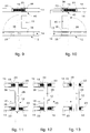
- the two lateral sections 28b and 28c of the base 28 are folded upwards (Figs. 2 and 6) and the levers 48 of the front cages 23 of the trolleys 13 are taken to the lowered position; the platform 12 is then moved substantially into close contact with the pier 15 which divides the two bays 44 (Fig. 7).
- the platform 12 is then made to translate transversely to take it to rest on one trolley 13 only, that is to say, on the trolley 13 provided with the turntable 36; to be more exact, the sliding element 31 is moved along the roller guides 32 and 33 until it is centered on the trolley 13 (Fig. 8).
- the platform 12 is subsequently made to rotate through 90° on the turntable 36 so as to be arranged adjacent to an outer side of the pier 15 and in a position parallel to the cables 14 (Fig. 9).
- the stabilizing rollers 45 located inside the C-shaped profiles 46 ensure considerable stability to the trolley 13, preventing any twisting thereof, or any transverse displacement or oscillation on a vertical plane, and hence more generally any movement which might release it from the cables 14 and from the rails 38.
- the two trolleys 13 After taking also the levers 48 of the rear cages 13 to the lowered position, the two trolleys 13 are made to advance simultaneously, with the wheels 24 and the toothed wheels 27 passing respectively on the rails 38 and the pins 42 and the stabilizing rollers 45 which slide inside the C-shaped profiles 46.
- the platform 12 is made to rotate by another 90°, returning to the orthogonal position with respect to the cables 14 (Fig. 10).
- the wheels 24, the toothed wheels 27 and the stabilizing rollers 45 of at least one cage 23 are always resting respectively on the rails 38, the pins 42 and the C-shaped profiles 46, so that the platform 12 is stably supported on a single side of the pier 15.
- the platform 12 is made to translate transversely, by moving the sliding element 31 on the roller guides 32 and 33, until it is returned to rest on both trolleys 13 (Fig. 11).
- the platform 12 is made to advance along the bay 44 so as to distance itself from the pier 15 (Fig. 12) and to allow the subsequent rotation of the lateral sections 28b and 28c of the base 28 to return the platform 12 to the open position and hence to the working condition (Fig. 13).
- the entire apparatus 10 can be driven and regulated remotely by means of a command and control unit, not shown in the drawings, which can be installed on the ground.
- the trolleys 13 can be moved along the same bay 44 by means of command means provided on board the platform 12.
- the trolleys 13 can be configured in a different manner and/or can move on rigid guides, for example of the rail type, instead of on cables 14.
Landscapes
- Engineering & Computer Science (AREA)
- Architecture (AREA)
- Civil Engineering (AREA)
- Structural Engineering (AREA)
- Bridges Or Land Bridges (AREA)
- Application Of Or Painting With Fluid Materials (AREA)
- Vehicle Cleaning, Maintenance, Repair, Refitting, And Outriggers (AREA)
- Electrical Discharge Machining, Electrochemical Machining, And Combined Machining (AREA)
- Vehicle Body Suspensions (AREA)
- Separation Using Semi-Permeable Membranes (AREA)
Applications Claiming Priority (2)
| Application Number | Priority Date | Filing Date | Title |
|---|---|---|---|
| IT2000UD000006A IT1314773B1 (it) | 2000-01-20 | 2000-01-20 | Apparato per la manutenzione di viadotti |
| ITUD000006 | 2000-01-20 |
Publications (3)
| Publication Number | Publication Date |
|---|---|
| EP1118716A2 true EP1118716A2 (fr) | 2001-07-25 |
| EP1118716A3 EP1118716A3 (fr) | 2002-01-23 |
| EP1118716B1 EP1118716B1 (fr) | 2006-11-29 |
Family
ID=11460181
Family Applications (1)
| Application Number | Title | Priority Date | Filing Date |
|---|---|---|---|
| EP01101016A Expired - Lifetime EP1118716B1 (fr) | 2000-01-20 | 2001-01-18 | Dispositif d'entretien de viaducs |
Country Status (5)
| Country | Link |
|---|---|
| EP (1) | EP1118716B1 (fr) |
| AT (1) | ATE346982T1 (fr) |
| DE (1) | DE60124796T2 (fr) |
| ES (1) | ES2277868T3 (fr) |
| IT (1) | IT1314773B1 (fr) |
Cited By (1)
| Publication number | Priority date | Publication date | Assignee | Title |
|---|---|---|---|---|
| CN112049004A (zh) * | 2020-09-29 | 2020-12-08 | 湖南哈工楚帆智能科技有限公司 | 水下桥墩检测装置 |
Families Citing this family (2)
| Publication number | Priority date | Publication date | Assignee | Title |
|---|---|---|---|---|
| CN106120552B (zh) * | 2016-06-27 | 2018-03-13 | 南京邮电大学 | 一种摩擦轮式爬索检测机器人 |
| CN111794096B (zh) * | 2020-06-19 | 2021-06-18 | 湖北工业大学 | 一种桥梁内侧主桁检查装置 |
Family Cites Families (2)
| Publication number | Priority date | Publication date | Assignee | Title |
|---|---|---|---|---|
| DE2612016A1 (de) * | 1976-03-20 | 1977-09-22 | Gerhard Dobersch | Verfahrbares arbeitsgeruest |
| AT402748B (de) * | 1991-04-16 | 1997-08-25 | Junger Baugesellschaft M B H U | Vorrichtung zur verwendung bei inspektions- und sanierungsarbeiten od.dgl. an brückenuntersichten |
-
2000
- 2000-01-20 IT IT2000UD000006A patent/IT1314773B1/it active
-
2001
- 2001-01-18 DE DE60124796T patent/DE60124796T2/de not_active Expired - Fee Related
- 2001-01-18 AT AT01101016T patent/ATE346982T1/de not_active IP Right Cessation
- 2001-01-18 ES ES01101016T patent/ES2277868T3/es not_active Expired - Lifetime
- 2001-01-18 EP EP01101016A patent/EP1118716B1/fr not_active Expired - Lifetime
Cited By (1)
| Publication number | Priority date | Publication date | Assignee | Title |
|---|---|---|---|---|
| CN112049004A (zh) * | 2020-09-29 | 2020-12-08 | 湖南哈工楚帆智能科技有限公司 | 水下桥墩检测装置 |
Also Published As
| Publication number | Publication date |
|---|---|
| EP1118716B1 (fr) | 2006-11-29 |
| ATE346982T1 (de) | 2006-12-15 |
| DE60124796D1 (de) | 2007-01-11 |
| ITUD20000006A1 (it) | 2001-07-20 |
| EP1118716A3 (fr) | 2002-01-23 |
| ES2277868T3 (es) | 2007-08-01 |
| IT1314773B1 (it) | 2003-01-16 |
| DE60124796T2 (de) | 2007-10-11 |
Similar Documents
| Publication | Publication Date | Title |
|---|---|---|
| US3571835A (en) | Apparatus for concreting multiple section structures, particularly bridge supports of reinforced or prestressed concrete | |
| CN109183618B (zh) | 一种用于预制装配式桥梁快速施工的架桥机 | |
| JP4515996B2 (ja) | 高架道橋の架設方法及び装置 | |
| EP1118716B1 (fr) | Dispositif d'entretien de viaducs | |
| KR20150070578A (ko) | 불규칙 경간을 갖는 구간의 거더 연속 시공방법 | |
| RU2112736C1 (ru) | Подъемно-транспортный агрегат | |
| US20060086568A1 (en) | Scaffolding structure | |
| KR102556238B1 (ko) | 터널 선로용 고소 작업 대차장치 | |
| CN107814143B (zh) | 一种用于伸缩皮带输送机上的操作站台 | |
| CN110273368B (zh) | 在架梁工位上架梁的方法 | |
| CN215715521U (zh) | 一种可跨钢支撑拼装地铁车站的台车中板拼装机构 | |
| JPS58523B2 (ja) | キヨウリヨウトウノ ジヨウブコウゾウコウチクソウチ | |
| CN118375069A (zh) | 桥梁混凝土防撞护栏模板台车及施工方法 | |
| CN212801239U (zh) | 一种简支梁桥盖梁钢筋二次张拉用移动挂篮台车 | |
| KR102206873B1 (ko) | 안전 기능이 향상된 4주식 차량 정비용 리프트 | |
| KR20040065446A (ko) | 노변용 2단 주차장치 | |
| CN210234958U (zh) | 一种高速铁路施工用搬运小车 | |
| JP2936471B2 (ja) | 二段駐車装置 | |
| CN110273366B (zh) | 具有可升降的多功能台车的导梁机 | |
| CN110273378B (zh) | 导梁机高、低位工位切换的方法 | |
| KR102556239B1 (ko) | 터널 선로용 고소 작업 대차 조립공법 | |
| CN110273367B (zh) | 低位工位架梁的方法 | |
| CN110273364B (zh) | 在架梁工位上架梁的方法 | |
| KR200191452Y1 (ko) | 교량점검대용 출입사다리 | |
| CN215715520U (zh) | 一种可跨钢支撑拼装地铁车站的台车行走机构 |
Legal Events
| Date | Code | Title | Description |
|---|---|---|---|
| PUAI | Public reference made under article 153(3) epc to a published international application that has entered the european phase |
Free format text: ORIGINAL CODE: 0009012 |
|
| AK | Designated contracting states |
Kind code of ref document: A2 Designated state(s): AT BE CH CY DE DK ES FI FR GB GR IE IT LI LU MC NL PT SE TR |
|
| AX | Request for extension of the european patent |
Free format text: AL;LT;LV;MK;RO;SI |
|
| PUAL | Search report despatched |
Free format text: ORIGINAL CODE: 0009013 |
|
| AK | Designated contracting states |
Kind code of ref document: A3 Designated state(s): AT BE CH CY DE DK ES FI FR GB GR IE IT LI LU MC NL PT SE TR |
|
| AX | Request for extension of the european patent |
Free format text: AL;LT;LV;MK;RO;SI |
|
| 17P | Request for examination filed |
Effective date: 20020719 |
|
| AKX | Designation fees paid |
Free format text: AT BE CH CY DE DK ES FI FR GB GR IE IT LI LU MC NL PT SE TR |
|
| GRAP | Despatch of communication of intention to grant a patent |
Free format text: ORIGINAL CODE: EPIDOSNIGR1 |
|
| GRAS | Grant fee paid |
Free format text: ORIGINAL CODE: EPIDOSNIGR3 |
|
| GRAA | (expected) grant |
Free format text: ORIGINAL CODE: 0009210 |
|
| AK | Designated contracting states |
Kind code of ref document: B1 Designated state(s): AT BE CH CY DE DK ES FI FR GB GR IE IT LI LU MC NL PT SE TR |
|
| PG25 | Lapsed in a contracting state [announced via postgrant information from national office to epo] |
Ref country code: BE Free format text: LAPSE BECAUSE OF FAILURE TO SUBMIT A TRANSLATION OF THE DESCRIPTION OR TO PAY THE FEE WITHIN THE PRESCRIBED TIME-LIMIT Effective date: 20061129 Ref country code: NL Free format text: LAPSE BECAUSE OF FAILURE TO SUBMIT A TRANSLATION OF THE DESCRIPTION OR TO PAY THE FEE WITHIN THE PRESCRIBED TIME-LIMIT Effective date: 20061129 Ref country code: CH Free format text: LAPSE BECAUSE OF FAILURE TO SUBMIT A TRANSLATION OF THE DESCRIPTION OR TO PAY THE FEE WITHIN THE PRESCRIBED TIME-LIMIT Effective date: 20061129 Ref country code: FI Free format text: LAPSE BECAUSE OF FAILURE TO SUBMIT A TRANSLATION OF THE DESCRIPTION OR TO PAY THE FEE WITHIN THE PRESCRIBED TIME-LIMIT Effective date: 20061129 Ref country code: LI Free format text: LAPSE BECAUSE OF FAILURE TO SUBMIT A TRANSLATION OF THE DESCRIPTION OR TO PAY THE FEE WITHIN THE PRESCRIBED TIME-LIMIT Effective date: 20061129 |
|
| RAP1 | Party data changed (applicant data changed or rights of an application transferred) |
Owner name: OMNIA SRL |
|
| REG | Reference to a national code |
Ref country code: GB Ref legal event code: FG4D |
|
| REG | Reference to a national code |
Ref country code: IE Ref legal event code: FG4D Ref country code: CH Ref legal event code: EP |
|
| REG | Reference to a national code |
Ref country code: IE Ref legal event code: FG4D |
|
| REF | Corresponds to: |
Ref document number: 60124796 Country of ref document: DE Date of ref document: 20070111 Kind code of ref document: P |
|
| PG25 | Lapsed in a contracting state [announced via postgrant information from national office to epo] |
Ref country code: IE Free format text: LAPSE BECAUSE OF NON-PAYMENT OF DUE FEES Effective date: 20070118 |
|
| PG25 | Lapsed in a contracting state [announced via postgrant information from national office to epo] |
Ref country code: MC Free format text: LAPSE BECAUSE OF NON-PAYMENT OF DUE FEES Effective date: 20070131 |
|
| PG25 | Lapsed in a contracting state [announced via postgrant information from national office to epo] |
Ref country code: SE Free format text: LAPSE BECAUSE OF FAILURE TO SUBMIT A TRANSLATION OF THE DESCRIPTION OR TO PAY THE FEE WITHIN THE PRESCRIBED TIME-LIMIT Effective date: 20070228 Ref country code: DK Free format text: LAPSE BECAUSE OF FAILURE TO SUBMIT A TRANSLATION OF THE DESCRIPTION OR TO PAY THE FEE WITHIN THE PRESCRIBED TIME-LIMIT Effective date: 20070228 |
|
| PG25 | Lapsed in a contracting state [announced via postgrant information from national office to epo] |
Ref country code: PT Free format text: LAPSE BECAUSE OF FAILURE TO SUBMIT A TRANSLATION OF THE DESCRIPTION OR TO PAY THE FEE WITHIN THE PRESCRIBED TIME-LIMIT Effective date: 20070430 |
|
| NLV1 | Nl: lapsed or annulled due to failure to fulfill the requirements of art. 29p and 29m of the patents act | ||
| REG | Reference to a national code |
Ref country code: CH Ref legal event code: PL |
|
| ET | Fr: translation filed | ||
| REG | Reference to a national code |
Ref country code: ES Ref legal event code: FG2A Ref document number: 2277868 Country of ref document: ES Kind code of ref document: T3 |
|
| PLBE | No opposition filed within time limit |
Free format text: ORIGINAL CODE: 0009261 |
|
| STAA | Information on the status of an ep patent application or granted ep patent |
Free format text: STATUS: NO OPPOSITION FILED WITHIN TIME LIMIT |
|
| GBPC | Gb: european patent ceased through non-payment of renewal fee |
Effective date: 20070228 |
|
| 26N | No opposition filed |
Effective date: 20070830 |
|
| PG25 | Lapsed in a contracting state [announced via postgrant information from national office to epo] |
Ref country code: GR Free format text: LAPSE BECAUSE OF FAILURE TO SUBMIT A TRANSLATION OF THE DESCRIPTION OR TO PAY THE FEE WITHIN THE PRESCRIBED TIME-LIMIT Effective date: 20070301 Ref country code: GB Free format text: LAPSE BECAUSE OF NON-PAYMENT OF DUE FEES Effective date: 20070228 |
|
| PGFP | Annual fee paid to national office [announced via postgrant information from national office to epo] |
Ref country code: DE Payment date: 20080730 Year of fee payment: 8 Ref country code: ES Payment date: 20080731 Year of fee payment: 8 |
|
| PGFP | Annual fee paid to national office [announced via postgrant information from national office to epo] |
Ref country code: AT Payment date: 20080731 Year of fee payment: 8 Ref country code: FR Payment date: 20080730 Year of fee payment: 8 Ref country code: IT Payment date: 20080731 Year of fee payment: 8 |
|
| PG25 | Lapsed in a contracting state [announced via postgrant information from national office to epo] |
Ref country code: LU Free format text: LAPSE BECAUSE OF NON-PAYMENT OF DUE FEES Effective date: 20070118 Ref country code: CY Free format text: LAPSE BECAUSE OF FAILURE TO SUBMIT A TRANSLATION OF THE DESCRIPTION OR TO PAY THE FEE WITHIN THE PRESCRIBED TIME-LIMIT Effective date: 20061129 |
|
| PG25 | Lapsed in a contracting state [announced via postgrant information from national office to epo] |
Ref country code: TR Free format text: LAPSE BECAUSE OF FAILURE TO SUBMIT A TRANSLATION OF THE DESCRIPTION OR TO PAY THE FEE WITHIN THE PRESCRIBED TIME-LIMIT Effective date: 20061129 |
|
| PG25 | Lapsed in a contracting state [announced via postgrant information from national office to epo] |
Ref country code: DE Free format text: LAPSE BECAUSE OF NON-PAYMENT OF DUE FEES Effective date: 20090801 Ref country code: AT Free format text: LAPSE BECAUSE OF NON-PAYMENT OF DUE FEES Effective date: 20090118 |
|
| REG | Reference to a national code |
Ref country code: FR Ref legal event code: ST Effective date: 20091030 |
|
| REG | Reference to a national code |
Ref country code: ES Ref legal event code: FD2A Effective date: 20090119 |
|
| PG25 | Lapsed in a contracting state [announced via postgrant information from national office to epo] |
Ref country code: ES Free format text: LAPSE BECAUSE OF NON-PAYMENT OF DUE FEES Effective date: 20090119 Ref country code: FR Free format text: LAPSE BECAUSE OF NON-PAYMENT OF DUE FEES Effective date: 20090202 |
|
| PG25 | Lapsed in a contracting state [announced via postgrant information from national office to epo] |
Ref country code: IT Free format text: LAPSE BECAUSE OF NON-PAYMENT OF DUE FEES Effective date: 20090118 |