EP1118733A2 - Konsole zur Befestigung des Tragrohrs einer Gelenkarm-Markise - Google Patents
Konsole zur Befestigung des Tragrohrs einer Gelenkarm-Markise Download PDFInfo
- Publication number
- EP1118733A2 EP1118733A2 EP00115177A EP00115177A EP1118733A2 EP 1118733 A2 EP1118733 A2 EP 1118733A2 EP 00115177 A EP00115177 A EP 00115177A EP 00115177 A EP00115177 A EP 00115177A EP 1118733 A2 EP1118733 A2 EP 1118733A2
- Authority
- EP
- European Patent Office
- Prior art keywords
- holding element
- support tube
- flanges
- console according
- circular
- Prior art date
- Legal status (The legal status is an assumption and is not a legal conclusion. Google has not performed a legal analysis and makes no representation as to the accuracy of the status listed.)
- Granted
Links
Images
Classifications
-
- E—FIXED CONSTRUCTIONS
- E04—BUILDING
- E04F—FINISHING WORK ON BUILDINGS, e.g. STAIRS, FLOORS
- E04F10/00—Sunshades, e.g. Florentine blinds or jalousies; Outside screens; Awnings or baldachins
- E04F10/02—Sunshades, e.g. Florentine blinds or jalousies; Outside screens; Awnings or baldachins of flexible canopy materials, e.g. canvas ; Baldachins
- E04F10/06—Sunshades, e.g. Florentine blinds or jalousies; Outside screens; Awnings or baldachins of flexible canopy materials, e.g. canvas ; Baldachins comprising a roller-blind with means for holding the end away from a building
- E04F10/0666—Accessories
- E04F10/0674—Accessories acting as separate supporting bar
-
- E—FIXED CONSTRUCTIONS
- E04—BUILDING
- E04F—FINISHING WORK ON BUILDINGS, e.g. STAIRS, FLOORS
- E04F10/00—Sunshades, e.g. Florentine blinds or jalousies; Outside screens; Awnings or baldachins
- E04F10/02—Sunshades, e.g. Florentine blinds or jalousies; Outside screens; Awnings or baldachins of flexible canopy materials, e.g. canvas ; Baldachins
- E04F10/06—Sunshades, e.g. Florentine blinds or jalousies; Outside screens; Awnings or baldachins of flexible canopy materials, e.g. canvas ; Baldachins comprising a roller-blind with means for holding the end away from a building
- E04F10/0637—Sunshades, e.g. Florentine blinds or jalousies; Outside screens; Awnings or baldachins of flexible canopy materials, e.g. canvas ; Baldachins comprising a roller-blind with means for holding the end away from a building with mechanisms for adjusting the inclination of the blind
-
- E—FIXED CONSTRUCTIONS
- E04—BUILDING
- E04F—FINISHING WORK ON BUILDINGS, e.g. STAIRS, FLOORS
- E04F10/00—Sunshades, e.g. Florentine blinds or jalousies; Outside screens; Awnings or baldachins
- E04F10/02—Sunshades, e.g. Florentine blinds or jalousies; Outside screens; Awnings or baldachins of flexible canopy materials, e.g. canvas ; Baldachins
- E04F10/06—Sunshades, e.g. Florentine blinds or jalousies; Outside screens; Awnings or baldachins of flexible canopy materials, e.g. canvas ; Baldachins comprising a roller-blind with means for holding the end away from a building
- E04F10/0662—Sunshades, e.g. Florentine blinds or jalousies; Outside screens; Awnings or baldachins of flexible canopy materials, e.g. canvas ; Baldachins comprising a roller-blind with means for holding the end away from a building with arrangements for fastening the blind to the building
Definitions
- the invention is directed to a bracket for fastening the support tube an articulated arm awning on a wall.
- Such consoles are known in different configurations and usually include an adjustment screw to adjust the incline to be able to accomplish.
- the object of the invention is such To improve the console so that easy assembly with easy tilt adjustment is given, with a special in the assembled state stable, tight fit should be guaranteed.
- a console comprising two at a distance and attached to the wall parallel to each other, perpendicular to the wall Flanges, each flange being a circular segment, the Radius of curvature of the support tube corresponding support section for the Carrier tube, with a circular segment-shaped between the flanges first, lower holding element is arranged, which is relative to the Flanges pivotally mounted about the central longitudinal axis of the support tube is and wherein a second circular segment-shaped holding element with the first holding element for fixing the support tube can be screwed.
- This configuration ensures that the support tube and thus connected awning parts after mounting the brackets on the wall the support surface can be stored, so that in the further determination and adjustment the weight does not have to be intercepted.
- the tilt adjustment can be done easily from below.
- the first holding element is approximately 3 ⁇ 4-circular and the second holding element is approximately 1 ⁇ 4 circle-shaped is so that the support tube is enclosed by both holding elements.
- first holding element with the second holding element in an approximately horizontal direction by a first fastening screw and by a second fastening screw in vertical Direction is connected.
- the first holding element can be tilted by means of an adjusting screw be that extends in approximately the vertical direction and can be operated from below is.
- the first holding element has a longitudinal recess has, which is penetrated by the screw, wherein in the Longitudinal recess a pivotally mounted in the second holding element Connection part is arranged, which has a threaded bore, in which engages the set screw.
- the free end of the set screw is advantageously supported on one End face of a connecting part between the two flanges.
- the flanges have at least one circular section, to the central longitudinal axis of the support tube concentric slot, the first Holding part has corresponding threaded holes in the outside engage the locking screws that penetrate the elongated holes.
- each flange there are two such on each flange at a distance from one another Elongated holes arranged.
- the support tube can have a longitudinal groove into which the first Holding element engages non-rotatably connected cams.
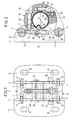
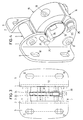
- a console shown in the drawing comprises two flanges 1, 2, which run parallel to each other at a distance from each other and over one first connecting element 3 with threaded holes 4 and screws 5 and via a second connecting element 6 with threaded bores 7 and screws 8 are interconnected.
- the flanges 1, 2 run perpendicular to the wall to which it is to be attached and have each extending parallel to this wall, perpendicular to the flanges extending neck 9 with screw holes 10.
- the flanges 1, 2 each have a bearing section 11, the one Has circular section-shaped top, which is concentric to the central longitudinal axis 12 of a support tube 13 of the articulated arm awning to be fastened runs and has the same radius of curvature as the support tube 13.
- a first holding element 14 can be pivoted between the flanges 1, 2 stored attached, which the configuration of a 3 ⁇ 4 circle and an inner Contact surface 16, which is circular segment-shaped, concentric runs to the central longitudinal axis 12 of the support tube 13 and the same radius of curvature as the support tube 13 has.
- a second holding element 15 is formed in a 1 ⁇ 4 circle and supplemented accordingly with the first holding element 14 to form a circular Element.
- the second holding element 15 also has an inner contact surface 16, which is shaped like a circular section, concentric to The central longitudinal axis 12 of the support tube 13 runs and has the same radius of curvature as this has.
- the first holding element 14 has a horizontally extending on its upper side Threaded hole 17 on.
- the second holding element 15 is with a vertical threaded bore 18 provided.
- a fastening screw 19 can through a horizontal bore 20 of the second holding element 15 screwed into the threaded bore 17 of the first holding element 14 become.
- Another mounting screw 21 is vertical Bore 22 of the first holding element 14 in the threaded bore 18th of the second holding element 15 can be screwed in from below.
- each Flange 1, 2 each have a lower and an upper elongated hole 23, 24, which have a circular section configuration and are concentric extend to the central longitudinal axis of the support tube 12.
- Fastening screws 25, 26, extend through the elongated holes 23, 24, which engage in threaded bores 27, 28 of the first holding element 14 and thus a bracing of the flanges 1, 2 relative to the first Allow holding element 14. This allows a set inclination fix the first holding element 14.
- the adjusting screw 29 runs in a recess 31 of the first holding element 14.
- a connecting part 32 is arranged with a threaded bore, which is set by the screw 29 with its external thread, the free end 33 of the set screw 29 on an end face 34 is supported on the connecting element 3. Accordingly, by twisting the set screw 29, the first holding element 14 can be pivoted.
Landscapes
- Engineering & Computer Science (AREA)
- Architecture (AREA)
- Civil Engineering (AREA)
- Structural Engineering (AREA)
- Building Awnings And Sunshades (AREA)
- Tents Or Canopies (AREA)
- Vehicle Step Arrangements And Article Storage (AREA)
- Supports For Pipes And Cables (AREA)
- Pivots And Pivotal Connections (AREA)
- Connection Of Plates (AREA)
Abstract
Description
Claims (9)
- Konsole zur Befestigung des Tragrohrs einer Gelenkarm-Markise an einer Wand umfassend zwei im Abstand und parallel zueinander an der Wand befestigter, senkrecht zur Wand verlaufende Flansche (1, 2), wobei jeder Flansch (1, 2) einen kreisabschnittförmigen, dem Krümmungsradius des Tragrohrs (13) entsprechenden Auflageabschnitt (11) für das Tragrohr (13) aufweist, wobei zwischen den Flanschen (1, 2) ein kreisabschnittförmiges erstes, unteres Halteelement (14) angeordnet ist, welches relativ zu den Flanschen (1, 2), um die Mittellängsachse des Tragrohrs (13) verschwenkbar gelagert ist, und wobei ein zweites, oberes kreisabschnittförmiges Halteelement (15) mit dem ersten Halteelement (14) zur Festlegung des Tragrohrs (13) verschraubbar ist.
- Konsole nach Anspruch 1, dadurch gekennzeichnet, daß das erste Halteelement (14) etwa ¾-Kreis-förmig und das zweite Halteelement (15) etwa ¼-Kreis-förmig ausgebildet ist.
- Konsole nach Anspruch 2, dadurch gekennzeichnet, daß das erste Halteelement (14) mit dem zweiten Halteelement (15) in etwa horizontaler Richtung durch eine erste Befestigungsschraube (19) und durch eine zweite Befestigungsschraube (21) in etwa vertikaler Richtung verbunden ist.
- Konsole nach Anspruch 2, dadurch gekennzeichnet, daß das erste Halteelement (14) mittels einer Stellschraube (29) neigungseinstellbar ist, die sich in etwa vertikaler Richtung erstreckt und von unten betätigbar ist.
- Konsole nach Anspruch 4, dadurch gekennzeichnet, daß das erste Halteelement (14) eine Längsausnehmung (31) aufweist, die von der Stellschraube (29) durchsetzt wird, wobei in der Längsausnehmung (31) ein im zweiten Halteelement (15) schwenkbar gelagertes Verbindungsteil (32) angeordnet ist, welches eine Gewindebohrung aufweist, in die die Stellschraube (29) eingreift.
- Konsole nach Anspruch 5, dadurch gekennzeichnet, daß das freie Ende (33) der Stellschraube (29) an einer Stirnfläche (34) eines Verbindungsteils (3) zwischen den beiden Flanschen (1, 2) abstützt.
- Konsole nach Anspruch 1, dadurch gekennzeichnet, daß die Flansche (1, 2) zur Bewerkstelligung der Neigungsverstellung des ersten Halteelements (14) wenigstens ein kreisabschnittförmiges, zur Mittellängsachse (12) des Tragrohrs (13) konzentrisches Langloch (23, 24) aufweisen, und daß das erste Halteteil (14) korrespondierende Gewindebohrungen aufweist, in die von außen die Langlöcher (23, 24) durchsetzende Feststellschrauben (25, 26) eingreifen.
- Konsole nach Anspruch 7, dadurch gekennzeichnet, daß an jedem Flansch (1, 2) im Abstand voneinander zwei Langlöcher (23, 24) angeordnet sind.
- Konsole nach Anspruch 1, dadurch gekennzeichnet, daß das Tragrohr (13) eine Längsnut (37) aufweist, in die ein mit dem ersten Halteelement (14) drehfest verbundener Nocken (36) eingreift.
Applications Claiming Priority (2)
| Application Number | Priority Date | Filing Date | Title |
|---|---|---|---|
| DE10001762A DE10001762A1 (de) | 2000-01-18 | 2000-01-18 | Konsole zur Befestigung des Tragrohrs einer Gelenkarm-Markise |
| DE10001762 | 2000-01-18 |
Publications (3)
| Publication Number | Publication Date |
|---|---|
| EP1118733A2 true EP1118733A2 (de) | 2001-07-25 |
| EP1118733A3 EP1118733A3 (de) | 2003-03-19 |
| EP1118733B1 EP1118733B1 (de) | 2006-06-07 |
Family
ID=7627789
Family Applications (1)
| Application Number | Title | Priority Date | Filing Date |
|---|---|---|---|
| EP00115177A Expired - Lifetime EP1118733B1 (de) | 2000-01-18 | 2000-07-13 | Konsole zur Befestigung des Tragrohrs einer Gelenkarm-Markise |
Country Status (8)
| Country | Link |
|---|---|
| US (1) | US6446917B2 (de) |
| EP (1) | EP1118733B1 (de) |
| JP (1) | JP2001241157A (de) |
| AT (1) | ATE329098T1 (de) |
| DE (2) | DE10001762A1 (de) |
| DK (1) | DK1118733T3 (de) |
| ES (1) | ES2265837T3 (de) |
| PT (1) | PT1118733E (de) |
Families Citing this family (29)
| Publication number | Priority date | Publication date | Assignee | Title |
|---|---|---|---|---|
| JP2001216400A (ja) * | 2000-02-04 | 2001-08-10 | Teikoku Databank Ltd | 電子商取引システム |
| AT411486B (de) * | 2001-01-26 | 2004-01-26 | Wien Kanal Abwassertech Gmbh | Vorrichtung zur befestigung von leitungen |
| US8510138B2 (en) * | 2009-03-06 | 2013-08-13 | Ticketmaster Llc | Networked barcode verification system |
| US9740988B1 (en) | 2002-12-09 | 2017-08-22 | Live Nation Entertainment, Inc. | System and method for using unique device indentifiers to enhance security |
| US9477820B2 (en) | 2003-12-09 | 2016-10-25 | Live Nation Entertainment, Inc. | Systems and methods for using unique device identifiers to enhance security |
| US10366373B1 (en) | 2002-12-09 | 2019-07-30 | Live Nation Entertainment, Incorporated | Apparatus for access control and processing |
| DE20306224U1 (de) | 2003-04-19 | 2003-06-18 | Schwarz Verbindungssysteme GmbH, 75382 Althengstett | Lösbare Halterungsanordnung für rohrförmige Bauteile |
| US20050065853A1 (en) * | 2003-09-18 | 2005-03-24 | Philip Ferreira | Reverse auction system and method |
| US8078483B1 (en) | 2003-12-16 | 2011-12-13 | Ticketmaster | Systems and methods for queuing access to network resources |
| US7584123B1 (en) * | 2004-04-06 | 2009-09-01 | Ticketmaster | Systems for dynamically allocating finite or unique resources |
| US9608929B2 (en) | 2005-03-22 | 2017-03-28 | Live Nation Entertainment, Inc. | System and method for dynamic queue management using queue protocols |
| US9762685B2 (en) | 2005-04-27 | 2017-09-12 | Live Nation Entertainment, Inc. | Location-based task execution for enhanced data access |
| US8668568B2 (en) * | 2005-04-27 | 2014-03-11 | Ticketmaster, L.L.C. | Methods and systems for determining user location |
| US20140379390A1 (en) | 2013-06-20 | 2014-12-25 | Live Nation Entertainment, Inc. | Location-based presentations of ticket opportunities |
| CA2932591C (en) | 2006-02-07 | 2023-07-25 | Ticketmaster | Methods and systems for reducing burst usage of a networked computer system |
| CA2651543C (en) | 2006-05-09 | 2016-02-16 | Ticketmaster | Apparatus for access control and processing |
| MX2009006019A (es) * | 2006-12-07 | 2009-12-09 | Ticketmaster L L C | Metodos y sistemas de control de acceso usando un torniquete conectado a una red. |
| US10348708B2 (en) | 2006-12-07 | 2019-07-09 | Live Nation Entertainment, Inc. | Short-range device interactions for facilitating partial uses of clustered access rights |
| WO2008152152A1 (es) * | 2007-06-11 | 2008-12-18 | Llaza, Sa | Conjunto de soporte para toldo con dispositivo de regulación de inclinación |
| AU2008283837B2 (en) | 2007-08-07 | 2013-08-22 | Ticketmaster, Llc | Systems and methods for providing resources allocation in a networked environment |
| US11843594B2 (en) | 2007-09-04 | 2023-12-12 | Live Nation Entertainment, Inc. | Controlled token distribution to protect against malicious data and resource access |
| US9781170B2 (en) | 2010-06-15 | 2017-10-03 | Live Nation Entertainment, Inc. | Establishing communication links using routing protocols |
| US10096161B2 (en) | 2010-06-15 | 2018-10-09 | Live Nation Entertainment, Inc. | Generating augmented reality images using sensor and location data |
| EP2583235A4 (de) | 2010-06-15 | 2014-01-22 | Ticketmaster L L C | Verfahren und systeme für computergestützte ereignis-und ortseinrichtung und modellierung und interaktive karten |
| KR101229394B1 (ko) | 2012-10-30 | 2013-02-12 | 주식회사 무진기연 | 다축 조절 스테이지 서포트 |
| US9228358B2 (en) * | 2012-12-23 | 2016-01-05 | Dometic Waeco International Gmbh | Self-supporting articulated-arm cassette awning for vehicles |
| DE202012012282U1 (de) | 2012-12-24 | 2014-04-04 | Dometic Waeco International Gmbh | Freitragende Gelenkarm-Kassetten-Markise für Fahrzeuge |
| USD735889S1 (en) | 2013-06-14 | 2015-08-04 | Schmitz-Werke Gmbh + Co. Kg | Awning holder |
| CN107009293A (zh) * | 2017-06-05 | 2017-08-04 | 大丰市天曌机械科技有限公司 | 一种多向固定管套 |
Family Cites Families (13)
| Publication number | Priority date | Publication date | Assignee | Title |
|---|---|---|---|---|
| US2292170A (en) * | 1939-09-16 | 1942-08-04 | William B Starkloff | Awning bracket |
| US3080140A (en) * | 1961-06-26 | 1963-03-05 | Electrical Fittings Corp | Clamp for conduit or the like |
| FR2165783A1 (de) * | 1971-12-28 | 1973-08-10 | Choffel Marius | |
| US3851979A (en) * | 1972-09-20 | 1974-12-03 | Woodhead Inc Daniel | Cable and hose clamp |
| FR2214035B2 (de) * | 1973-01-15 | 1976-08-27 | Choffel Marius | |
| DE2319376A1 (de) * | 1973-04-17 | 1974-10-31 | Barth Markise Helmuth Barth | Markisenbefestigung |
| US4281213A (en) * | 1980-03-20 | 1981-07-28 | General Electric Company | Insulating support structure for an electric bus conductor |
| US4442994A (en) * | 1982-02-02 | 1984-04-17 | Logsdon Duane D | Pipe hanger capable of totally encircling a pipe |
| DE3611534A1 (de) * | 1986-04-05 | 1987-10-15 | Rasmussen Gmbh | Schraubloser rohrhalter |
| FR2662726A1 (fr) * | 1990-06-05 | 1991-12-06 | Zapparata Biagio | Ensemble support de toile de store et procede de realisation du bras support. |
| IT1279310B1 (it) * | 1995-06-07 | 1997-12-09 | Elios Snc Di Cadorin Sergio & | Sistema di orientamento dell'inclinazione per tenda a braccia |
| US5689862A (en) * | 1996-05-02 | 1997-11-25 | Spm, Inc. | Safety clamp |
| DE29612904U1 (de) * | 1996-07-25 | 1996-09-26 | Schmitz-Werke GmbH + Co, 48282 Emsdetten | Gelenkarm-Markise |
-
2000
- 2000-01-18 DE DE10001762A patent/DE10001762A1/de not_active Withdrawn
- 2000-07-13 AT AT00115177T patent/ATE329098T1/de active
- 2000-07-13 EP EP00115177A patent/EP1118733B1/de not_active Expired - Lifetime
- 2000-07-13 DE DE50012913T patent/DE50012913D1/de not_active Expired - Lifetime
- 2000-07-13 DK DK00115177T patent/DK1118733T3/da active
- 2000-07-13 ES ES00115177T patent/ES2265837T3/es not_active Expired - Lifetime
- 2000-07-13 PT PT00115177T patent/PT1118733E/pt unknown
-
2001
- 2001-01-16 JP JP2001008010A patent/JP2001241157A/ja active Pending
- 2001-01-18 US US09/761,664 patent/US6446917B2/en not_active Expired - Fee Related
Also Published As
| Publication number | Publication date |
|---|---|
| JP2001241157A (ja) | 2001-09-04 |
| PT1118733E (pt) | 2006-10-31 |
| DK1118733T3 (da) | 2006-10-02 |
| US6446917B2 (en) | 2002-09-10 |
| ATE329098T1 (de) | 2006-06-15 |
| US20010008264A1 (en) | 2001-07-19 |
| DE10001762A1 (de) | 2001-07-19 |
| EP1118733B1 (de) | 2006-06-07 |
| EP1118733A3 (de) | 2003-03-19 |
| DE50012913D1 (de) | 2006-07-20 |
| ES2265837T3 (es) | 2007-03-01 |
Similar Documents
| Publication | Publication Date | Title |
|---|---|---|
| EP1118733B1 (de) | Konsole zur Befestigung des Tragrohrs einer Gelenkarm-Markise | |
| EP0200744A1 (de) | Scharnier. | |
| WO1991017329A1 (de) | Gelenkarmmarkise | |
| EP0786563B1 (de) | Gestell, insbesondere zur Befestigung von Sanitärapparaten | |
| EP0225609A2 (de) | Scharnier | |
| EP0821118B1 (de) | Gelenkarm-Markise | |
| EP0808961B1 (de) | Gelenkarmmarkise | |
| EP1215348B1 (de) | Gelenkarm-Markise | |
| EP0960983A2 (de) | Beplankungsvorrichtung einer Wandhalterung | |
| EP1022397B1 (de) | Schwenkbare Wandstange für Brausegarnituren | |
| EP1127519B1 (de) | Beschlag für Sitz- oder Liegemöbel | |
| EP1577476B1 (de) | Scharnier zur drehbaren Halterung einer Tür oder eines Fensters an einem Rahmen | |
| DE19940010A1 (de) | Antennenträgeranorndung | |
| EP3388690B1 (de) | Konsole zur befestigung von versorgungsleitungen oder dergleichen an einer wand | |
| DE4111754C2 (de) | Monitor-Tragarm | |
| EP2787142A2 (de) | Freitragende Gelenkarm-Kassetten-Markise für Fahrzeuge | |
| EP3000950B1 (de) | Wandkonsole für eine markise mit neigungsverstellung | |
| DE3423075C2 (de) | ||
| DE9204966U1 (de) | Aufbewahrungsvorrichtung für Fahrräder | |
| EP1247717B1 (de) | Halterungseinrichtung für ein Signal, insbesondere für ein Eisenbahnsignal | |
| DE9318456U1 (de) | Lagervorrichtung für Gelenkarme von Markisen | |
| DE2236397C2 (de) | Einstellbarer Aufhängebeschlag für Wandschränke | |
| DE10045582C1 (de) | Gelenkarm-Markise | |
| EP1096075A2 (de) | Wandhalterung zur Befestigung eines Montagegestells an einer Wand | |
| DE102020213049B3 (de) | Montagehalter zur Montage einer Markise an einem Gebäude und damit ausgerüstete Markise |
Legal Events
| Date | Code | Title | Description |
|---|---|---|---|
| PUAI | Public reference made under article 153(3) epc to a published international application that has entered the european phase |
Free format text: ORIGINAL CODE: 0009012 |
|
| AK | Designated contracting states |
Kind code of ref document: A2 Designated state(s): AT BE CH CY DE DK ES FI FR GB GR IE IT LI LU MC NL PT SE |
|
| AX | Request for extension of the european patent |
Free format text: AL;LT;LV;MK;RO;SI |
|
| PUAL | Search report despatched |
Free format text: ORIGINAL CODE: 0009013 |
|
| AK | Designated contracting states |
Kind code of ref document: A3 Designated state(s): AT BE CH CY DE DK ES FI FR GB GR IE IT LI LU MC NL PT SE |
|
| AX | Request for extension of the european patent |
Extension state: AL LT LV MK RO SI |
|
| 17P | Request for examination filed |
Effective date: 20030205 |
|
| AKX | Designation fees paid |
Designated state(s): AT BE CH CY DE DK ES FI FR GB GR IE IT LI LU MC NL PT SE |
|
| GRAP | Despatch of communication of intention to grant a patent |
Free format text: ORIGINAL CODE: EPIDOSNIGR1 |
|
| GRAS | Grant fee paid |
Free format text: ORIGINAL CODE: EPIDOSNIGR3 |
|
| GRAA | (expected) grant |
Free format text: ORIGINAL CODE: 0009210 |
|
| AK | Designated contracting states |
Kind code of ref document: B1 Designated state(s): AT BE CH CY DE DK ES FI FR GB GR IE IT LI LU MC NL PT SE |
|
| REG | Reference to a national code |
Ref country code: GB Ref legal event code: FG4D Free format text: NOT ENGLISH |
|
| REG | Reference to a national code |
Ref country code: CH Ref legal event code: EP |
|
| GBT | Gb: translation of ep patent filed (gb section 77(6)(a)/1977) |
Effective date: 20060607 |
|
| REG | Reference to a national code |
Ref country code: IE Ref legal event code: FG4D Free format text: LANGUAGE OF EP DOCUMENT: GERMAN |
|
| REF | Corresponds to: |
Ref document number: 50012913 Country of ref document: DE Date of ref document: 20060720 Kind code of ref document: P |
|
| PG25 | Lapsed in a contracting state [announced via postgrant information from national office to epo] |
Ref country code: MC Free format text: LAPSE BECAUSE OF NON-PAYMENT OF DUE FEES Effective date: 20060731 |
|
| REG | Reference to a national code |
Ref country code: SE Ref legal event code: TRGR |
|
| REG | Reference to a national code |
Ref country code: DK Ref legal event code: T3 |
|
| REG | Reference to a national code |
Ref country code: GR Ref legal event code: EP Ref document number: 20060402900 Country of ref document: GR |
|
| REG | Reference to a national code |
Ref country code: PT Ref legal event code: SC4A Effective date: 20060831 |
|
| ET | Fr: translation filed | ||
| REG | Reference to a national code |
Ref country code: ES Ref legal event code: FG2A Ref document number: 2265837 Country of ref document: ES Kind code of ref document: T3 |
|
| PLBE | No opposition filed within time limit |
Free format text: ORIGINAL CODE: 0009261 |
|
| STAA | Information on the status of an ep patent application or granted ep patent |
Free format text: STATUS: NO OPPOSITION FILED WITHIN TIME LIMIT |
|
| 26N | No opposition filed |
Effective date: 20070308 |
|
| PG25 | Lapsed in a contracting state [announced via postgrant information from national office to epo] |
Ref country code: CY Free format text: LAPSE BECAUSE OF FAILURE TO SUBMIT A TRANSLATION OF THE DESCRIPTION OR TO PAY THE FEE WITHIN THE PRESCRIBED TIME-LIMIT Effective date: 20060607 |
|
| REG | Reference to a national code |
Ref country code: FR Ref legal event code: PLFP Year of fee payment: 17 |
|
| REG | Reference to a national code |
Ref country code: FR Ref legal event code: PLFP Year of fee payment: 18 |
|
| PGFP | Annual fee paid to national office [announced via postgrant information from national office to epo] |
Ref country code: CH Payment date: 20170613 Year of fee payment: 18 |
|
| PGFP | Annual fee paid to national office [announced via postgrant information from national office to epo] |
Ref country code: LU Payment date: 20170720 Year of fee payment: 18 |
|
| PGFP | Annual fee paid to national office [announced via postgrant information from national office to epo] |
Ref country code: NL Payment date: 20170720 Year of fee payment: 18 |
|
| PGFP | Annual fee paid to national office [announced via postgrant information from national office to epo] |
Ref country code: FI Payment date: 20170719 Year of fee payment: 18 Ref country code: FR Payment date: 20170720 Year of fee payment: 18 Ref country code: GB Payment date: 20170724 Year of fee payment: 18 Ref country code: ES Payment date: 20170818 Year of fee payment: 18 Ref country code: GR Payment date: 20170725 Year of fee payment: 18 Ref country code: DE Payment date: 20170925 Year of fee payment: 18 Ref country code: IT Payment date: 20170721 Year of fee payment: 18 |
|
| PGFP | Annual fee paid to national office [announced via postgrant information from national office to epo] |
Ref country code: AT Payment date: 20170616 Year of fee payment: 18 Ref country code: SE Payment date: 20170724 Year of fee payment: 18 Ref country code: DK Payment date: 20170724 Year of fee payment: 18 Ref country code: IE Payment date: 20170724 Year of fee payment: 18 Ref country code: PT Payment date: 20170705 Year of fee payment: 18 Ref country code: BE Payment date: 20170720 Year of fee payment: 18 |
|
| REG | Reference to a national code |
Ref country code: DE Ref legal event code: R119 Ref document number: 50012913 Country of ref document: DE |
|
| REG | Reference to a national code |
Ref country code: DK Ref legal event code: EBP Effective date: 20180731 |
|
| REG | Reference to a national code |
Ref country code: CH Ref legal event code: PL |
|
| REG | Reference to a national code |
Ref country code: NL Ref legal event code: MM Effective date: 20180801 |
|
| REG | Reference to a national code |
Ref country code: AT Ref legal event code: MM01 Ref document number: 329098 Country of ref document: AT Kind code of ref document: T Effective date: 20180713 |
|
| GBPC | Gb: european patent ceased through non-payment of renewal fee |
Effective date: 20180713 |
|
| PG25 | Lapsed in a contracting state [announced via postgrant information from national office to epo] |
Ref country code: LU Free format text: LAPSE BECAUSE OF NON-PAYMENT OF DUE FEES Effective date: 20180713 |
|
| REG | Reference to a national code |
Ref country code: BE Ref legal event code: MM Effective date: 20180731 |
|
| REG | Reference to a national code |
Ref country code: IE Ref legal event code: MM4A |
|
| PG25 | Lapsed in a contracting state [announced via postgrant information from national office to epo] |
Ref country code: AT Free format text: LAPSE BECAUSE OF NON-PAYMENT OF DUE FEES Effective date: 20180713 Ref country code: IE Free format text: LAPSE BECAUSE OF NON-PAYMENT OF DUE FEES Effective date: 20180713 Ref country code: FI Free format text: LAPSE BECAUSE OF NON-PAYMENT OF DUE FEES Effective date: 20180713 Ref country code: GB Free format text: LAPSE BECAUSE OF NON-PAYMENT OF DUE FEES Effective date: 20180713 Ref country code: CH Free format text: LAPSE BECAUSE OF NON-PAYMENT OF DUE FEES Effective date: 20180731 Ref country code: DE Free format text: LAPSE BECAUSE OF NON-PAYMENT OF DUE FEES Effective date: 20190201 Ref country code: LI Free format text: LAPSE BECAUSE OF NON-PAYMENT OF DUE FEES Effective date: 20180731 Ref country code: FR Free format text: LAPSE BECAUSE OF NON-PAYMENT OF DUE FEES Effective date: 20180731 |
|
| PG25 | Lapsed in a contracting state [announced via postgrant information from national office to epo] |
Ref country code: PT Free format text: LAPSE BECAUSE OF NON-PAYMENT OF DUE FEES Effective date: 20190114 Ref country code: SE Free format text: LAPSE BECAUSE OF NON-PAYMENT OF DUE FEES Effective date: 20180714 Ref country code: NL Free format text: LAPSE BECAUSE OF NON-PAYMENT OF DUE FEES Effective date: 20180801 Ref country code: GR Free format text: LAPSE BECAUSE OF NON-PAYMENT OF DUE FEES Effective date: 20190207 Ref country code: BE Free format text: LAPSE BECAUSE OF NON-PAYMENT OF DUE FEES Effective date: 20180731 |
|
| PG25 | Lapsed in a contracting state [announced via postgrant information from national office to epo] |
Ref country code: IT Free format text: LAPSE BECAUSE OF NON-PAYMENT OF DUE FEES Effective date: 20180713 Ref country code: DK Free format text: LAPSE BECAUSE OF NON-PAYMENT OF DUE FEES Effective date: 20180731 |
|
| REG | Reference to a national code |
Ref country code: ES Ref legal event code: FD2A Effective date: 20190917 |
|
| PG25 | Lapsed in a contracting state [announced via postgrant information from national office to epo] |
Ref country code: ES Free format text: LAPSE BECAUSE OF NON-PAYMENT OF DUE FEES Effective date: 20180714 |