EP1118863A2 - Dispositif pour tester et/ou influencer l'écoulement d'un fluide - Google Patents
Dispositif pour tester et/ou influencer l'écoulement d'un fluide Download PDFInfo
- Publication number
- EP1118863A2 EP1118863A2 EP01100292A EP01100292A EP1118863A2 EP 1118863 A2 EP1118863 A2 EP 1118863A2 EP 01100292 A EP01100292 A EP 01100292A EP 01100292 A EP01100292 A EP 01100292A EP 1118863 A2 EP1118863 A2 EP 1118863A2
- Authority
- EP
- European Patent Office
- Prior art keywords
- piston
- flow
- valve
- fluid
- section
- Prior art date
- Legal status (The legal status is an assumption and is not a legal conclusion. Google has not performed a legal analysis and makes no representation as to the accuracy of the status listed.)
- Withdrawn
Links
Images

Classifications
-
- F—MECHANICAL ENGINEERING; LIGHTING; HEATING; WEAPONS; BLASTING
- F16—ENGINEERING ELEMENTS AND UNITS; GENERAL MEASURES FOR PRODUCING AND MAINTAINING EFFECTIVE FUNCTIONING OF MACHINES OR INSTALLATIONS; THERMAL INSULATION IN GENERAL
- F16K—VALVES; TAPS; COCKS; ACTUATING-FLOATS; DEVICES FOR VENTING OR AERATING
- F16K31/00—Actuating devices; Operating means; Releasing devices
- F16K31/02—Actuating devices; Operating means; Releasing devices electric; magnetic
- F16K31/06—Actuating devices; Operating means; Releasing devices electric; magnetic using a magnet, e.g. diaphragm valves, cutting off by means of a liquid
- F16K31/0644—One-way valve
- F16K31/0668—Sliding valves
-
- F—MECHANICAL ENGINEERING; LIGHTING; HEATING; WEAPONS; BLASTING
- F16—ENGINEERING ELEMENTS AND UNITS; GENERAL MEASURES FOR PRODUCING AND MAINTAINING EFFECTIVE FUNCTIONING OF MACHINES OR INSTALLATIONS; THERMAL INSULATION IN GENERAL
- F16K—VALVES; TAPS; COCKS; ACTUATING-FLOATS; DEVICES FOR VENTING OR AERATING
- F16K1/00—Lift valves or globe valves, i.e. cut-off apparatus with closure members having at least a component of their opening and closing motion perpendicular to the closing faces
- F16K1/12—Lift valves or globe valves, i.e. cut-off apparatus with closure members having at least a component of their opening and closing motion perpendicular to the closing faces with streamlined valve member around which the fluid flows when the valve is opened
- F16K1/123—Lift valves or globe valves, i.e. cut-off apparatus with closure members having at least a component of their opening and closing motion perpendicular to the closing faces with streamlined valve member around which the fluid flows when the valve is opened with stationary valve member and moving sleeve
-
- F—MECHANICAL ENGINEERING; LIGHTING; HEATING; WEAPONS; BLASTING
- F16—ENGINEERING ELEMENTS AND UNITS; GENERAL MEASURES FOR PRODUCING AND MAINTAINING EFFECTIVE FUNCTIONING OF MACHINES OR INSTALLATIONS; THERMAL INSULATION IN GENERAL
- F16K—VALVES; TAPS; COCKS; ACTUATING-FLOATS; DEVICES FOR VENTING OR AERATING
- F16K31/00—Actuating devices; Operating means; Releasing devices
- F16K31/02—Actuating devices; Operating means; Releasing devices electric; magnetic
- F16K31/06—Actuating devices; Operating means; Releasing devices electric; magnetic using a magnet, e.g. diaphragm valves, cutting off by means of a liquid
- F16K31/0644—One-way valve
- F16K31/0651—One-way valve the fluid passing through the solenoid coil
-
- G—PHYSICS
- G01—MEASURING; TESTING
- G01F—MEASURING VOLUME, VOLUME FLOW, MASS FLOW OR LIQUID LEVEL; METERING BY VOLUME
- G01F1/00—Measuring the volume flow or mass flow of fluid or fluent solid material wherein the fluid passes through a meter in a continuous flow
- G01F1/05—Measuring the volume flow or mass flow of fluid or fluent solid material wherein the fluid passes through a meter in a continuous flow by using mechanical effects
- G01F1/20—Measuring the volume flow or mass flow of fluid or fluent solid material wherein the fluid passes through a meter in a continuous flow by using mechanical effects by detection of dynamic effects of the flow
- G01F1/22—Measuring the volume flow or mass flow of fluid or fluent solid material wherein the fluid passes through a meter in a continuous flow by using mechanical effects by detection of dynamic effects of the flow by variable-area meters, e.g. rotameters
- G01F1/26—Measuring the volume flow or mass flow of fluid or fluent solid material wherein the fluid passes through a meter in a continuous flow by using mechanical effects by detection of dynamic effects of the flow by variable-area meters, e.g. rotameters of the valve type
-
- G—PHYSICS
- G01—MEASURING; TESTING
- G01P—MEASURING LINEAR OR ANGULAR SPEED, ACCELERATION, DECELERATION, OR SHOCK; INDICATING PRESENCE, ABSENCE, OR DIRECTION, OF MOVEMENT
- G01P13/00—Indicating or recording presence, absence, or direction, of movement
- G01P13/0006—Indicating or recording presence, absence, or direction, of movement of fluids or of granulous or powder-like substances
- G01P13/0013—Indicating or recording presence, absence, or direction, of movement of fluids or of granulous or powder-like substances by using a solid body which is shifted by the action of the fluid
-
- G—PHYSICS
- G05—CONTROLLING; REGULATING
- G05D—SYSTEMS FOR CONTROLLING OR REGULATING NON-ELECTRIC VARIABLES
- G05D7/00—Control of flow
- G05D7/01—Control of flow without auxiliary power
- G05D7/0126—Control of flow without auxiliary power the sensing element being a piston or plunger associated with one or more springs
- G05D7/0133—Control of flow without auxiliary power the sensing element being a piston or plunger associated with one or more springs within the flow-path
Definitions
- Fluids such as liquids
- Valves are arranged in the line systems, both proportional valves and such valves, which are only switched on and off. There is a need to be able to check whether after opening a valve a current actually takes place. Devices with which this can be determined, flow monitors are often used called.
- the invention has for its object a device for checking and / or influencing the flow in one To create fluid with which the operation of valves can be checked and / or improved.
- the invention proposes a device with the features of claim 1. Training the invention are the subject of the dependent claims, the Wording as well as the wording of the summary Reference is made to the content of the description.
- the piston is arranged so that it is from the flow of the fluid to be checked applied to its front becomes. On its back, it is exposed to the outflow acted upon. Due to the pressure difference in the fluid between the front and back of the piston, the for example due to a reduction in cross-section results, the piston is acted upon to different degrees. It is therefore counteracted by the pressure difference against the effect of Spring moves. This movement is from the tapping device detected. This can be designed, for example, that leaving the piston from the position in which he is found when there is no flow and is displayed. It is also possible that Reaching a position different from this starting position is determined and ascertained.
- the piston can, for example, be arranged in the bypass flow of the fluid become.
- the Device for removing the position of the piston one in particular is a non-contact sensor or detector.
- detectors are known per se.
- reed switches or light barriers are known per se.
- the device for Decrease in the position of the piston works in several positions, that means recognizing several positions of the piston and can distinguish. It can be both a discontinuous facility as well in particular is a continuously operating institution, which can determine the exact position of the piston.
- the device for removing the position of the piston can in Development of the invention a movable part of an associated Be valve, especially the closure body of the Valve. In this way, the one proposed by the invention Device serve a volume flow control valve to build.
- the movable piston in a bore or a line piece is arranged to reduce the caused by the flow through the cross section of the bore. This can happen, for example, that the piston is designed as a float and the flow between flows through it and the wall of the hole.
- the Piston between two extreme positions arranged to be movable is.
- the pressure difference between the front and the rear of the piston is changeable or adjustable, preferably also during the flow of the fluid. To this The response point of the detector or the Change the target position of an assigned valve.
- reducing the flow area and so that the pressure difference depends on the position of the piston is. This can be done, for example, by changing the geometry be achieved so that when the piston moves the cross-section of the remaining area changes.
- the device is arranged in the flow path of a valve. This can be done both in front of the valve and behind the valve his. So that the device can be used to Check the operation of the valve. In particular, can the device with the valve combined in one assembly become.
- One way to set the pressure differential is that the piston is in the direction of flow has laterally open notch into which a throttle element reaching through the wall of a line intervenes.
- This throttle element can, for example intervene differently, or it cannot have a circular cross section and are rotated. In In both cases, the flow cross section between the Notch and the throttle element changed.
- the notch or a other opening is not constant in the direction of flow Has cross-sectional area. This changes when responding the cross-sectional area of the piston and thus the pressure difference. In this way, the control curves of the Flow monitor or a valve connected to it almost design as desired.
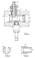
- Figure 1 shows an axial section of a device according to the Invention as used as a flow switch can.
- a line section for example part of a Line
- an axial passage 2 is formed, hereinafter referred to simply as a bore for the sake of simplicity even if it's a little more complicated.
- a piston 4 is arranged, which is indicated by a spring 5 is loaded to the left in Figure 1.
- the flow direction for a fluid is from left to right.
- the Compression spring acts on the piston 4 against the direction of flow.
- the piston is approximately cylindrical in shape with a Incision or notch 6 on. He can be between the two Snap rings 3 are moved back and forth. A special one Leadership is not required for him.
- the spring is supported on one shoulder of the piston and on the snap ring 3.
- an inductively working sensor 7 is screwed in.
- the actual Sensor 8 is flush with the wall of bore 2 arranged.
- the sensor 7 can determine the position of the piston 4. For example, the sensor 7 responds when the piston 4 from the position shown in the longitudinal direction the extension of the transducer 8 measured in the bore 2 is shifted to the right.
- a socket 9 is screwed into the wall of the line section 1, which contains a passage for a throttle element 10.
- the throttle element 10 has part of it Length of an external thread 11, which in a corresponding internal thread the socket 9 engages.
- On the inside of the Bore 2 protruding end 12 is the throttle element 10 smoothly formed. This inner end 12 protrudes into the notch 6 the piston 4 into it. By rotating the throttle element 10 this can be more or less far inside the Screw hole 2 into it, and thus into notch 6.
- the selected position of the throttle element 10 can by a Lock nut 13 are fixed.
- the throttle element 10 has in the area of its end 12 projecting into the interior of the notch 6 a circular cross-section.
- Figure 2 shows an end view of the piston 4 from the left in Figure 1.
- the piston 4 has the shape of a cylinder an outer diameter approximately the same as the diameter of the bore 2 on. On its face, see Figure 2, is one Sink present.
- the notch 6 already mentioned extends itself as a slot from the radial outside of the piston 4 to over the middle of the diameter.
- the depth of the notch 6 is everywhere in the example shown, see Figure 1 equal.
- Figure 3 shows a horizontal longitudinal section through the Piston 4 of Figures 1 and 2. It can be seen that the notch 6 also a constant in the longitudinal direction of the piston 4 Width.
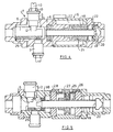
- Figure 4 shows in a common valve housing 15 a coaxial valve 16 and a flow switch 17, as it was schematically explained in Figure 1.
- the figure 4 shows the coaxial valve 16 in the closed state. It contains as a closure element a tube 18 which with a sharp edge 19 on the right in FIG. 4 on a valve seat 20 sits on.
- the tube 18 is on the outside with the anchor 21 connected to a magnet, which is not an individual includes solenoid 22 shown. If through the coil 22nd a current flows, the tube 18 is lifted off the valve seat 20, that is, moved to the left in Figure 4. Open in the process then passages 23 through which the fluid after it passes the tube 18 has flowed, can flow out of the valve. Details of these coaxial valves are not explained in detail, since they are known.
- a Piston 25 In a bore 24 leading to the coaxial valve 16 is a Piston 25 arranged in the same way as this under 1 has already been explained.
- This one too Piston 25 has a notch 6 into which the inner end 12 of a throttle element 10 engages more or less.
- the change in the position of the piston 25 can again by a sensor 7 can be determined.
- the one mentioned in Figure 1 Spring 5 is not shown here for the sake of simplicity.
- the through the piston 25, the throttle element 10, the bore 24 and the sensor 7 formed flow switch is in the Flow path of the coaxial valve 16 arranged in the illustrated Example immediately before this coaxial valve.
- the Flow switch forms a structural unit with the coaxial valve.
- Figure 5 shows, also in a longitudinal section, a coaxial valve 26, in which the tube 18 on the outside with a Piston 27 is connected.
- the piston is, along with that Tube 18, slidable.
- a pressure chamber 28, 29 into which a fluid, for example Compressed air, can be introduced.
- a fluid for example Compressed air
- the front end 30 of the tube when viewed in the direction of flow 18, which forms the closure body, is with a piston 35 connected.
- the piston 35 is so with the movement of the Tube 18 with moves.
- the piston is constructed similarly as in the previous embodiments, the That is, it has a notch 6, into which a not explained Throttle element 10 engages with its free end 12.
- a sensor 7 is again present. With the help of the Pressure chambers 28, 29 prevailing pressures, the valve is opened or closed. The opening position should be one correspond to a certain volume flow. The regulation of this Volume flow takes place through the part of the unit that is at the previous embodiment as a flow switch worked.
- valve housing which forms the valve seat.
- the valve is closed.
- the conical one sits on the valve seat Closure body 37. He is in the area of his one end in an opening with a guide portion 38 guided.
- the closure body On the opposite side is the closure body connected to a piston 39, which in turn with a stem 40 into a space outside of the flow path protrudes.
- a further piston 41 attached to the shaft 40, so acted upon by an indicated compression spring 42 is that the valve remains closed.
- To open of the valve is through the opening in the upper in Figure 6 End cover in the direction of the indicated arrow pressure introduced, for example compressed air. This will make the closure body 37 moved so that it from the valve seat is lifted off. If this control pressure is switched off, the valve closed again.
- the valve housing contains an inlet opening 45 for the controlling fluid.
- the inlet opening 45 leads into a room on one side of the piston 39, namely on its front.
- a line 44 leads from this room to a Reduced cross-section on the opposite side of the Piston 39, which therefore on this side from the pressure of the the line 44 flowing liquid is applied.
- the valve leads from this space to the outlet opening 43.
- valve is again a volume flow control valve.
- the reduction in cross section in the line 44 can be adjusted by a throttle element 46 that can be rotated around its axis. Then poses the throttle end 47 of the throttle element 46 extends transversely and projects thereby more into the lines 44.
- the Throttle element 46 by means of a thread more or less screw far into line 44. This also leads to a change in cross-sectional reduction.
Landscapes
- Engineering & Computer Science (AREA)
- General Engineering & Computer Science (AREA)
- Physics & Mathematics (AREA)
- Mechanical Engineering (AREA)
- General Physics & Mathematics (AREA)
- Fluid Mechanics (AREA)
- Automation & Control Theory (AREA)
- Indication Of The Valve Opening Or Closing Status (AREA)
Applications Claiming Priority (2)
| Application Number | Priority Date | Filing Date | Title |
|---|---|---|---|
| DE2000100178 DE10000178A1 (de) | 2000-01-05 | 2000-01-05 | Einrichtung zum Überprüfen und/oder Beeinflussen der Strömung in einem Fluid |
| DE10000178 | 2000-01-05 |
Publications (2)
| Publication Number | Publication Date |
|---|---|
| EP1118863A2 true EP1118863A2 (fr) | 2001-07-25 |
| EP1118863A3 EP1118863A3 (fr) | 2002-11-27 |
Family
ID=7626774
Family Applications (1)
| Application Number | Title | Priority Date | Filing Date |
|---|---|---|---|
| EP01100292A Withdrawn EP1118863A3 (fr) | 2000-01-05 | 2001-01-04 | Dispositif pour tester et/ou influencer l'écoulement d'un fluide |
Country Status (2)
| Country | Link |
|---|---|
| EP (1) | EP1118863A3 (fr) |
| DE (1) | DE10000178A1 (fr) |
Cited By (3)
| Publication number | Priority date | Publication date | Assignee | Title |
|---|---|---|---|---|
| CN104459189A (zh) * | 2014-12-05 | 2015-03-25 | 四川凌峰航空液压机械有限公司 | 作动筒活塞杆任意行程测速装置 |
| US10684154B2 (en) | 2016-12-12 | 2020-06-16 | Ventbuster Holdings Inc. | Gas meter and associated methods |
| CN114923514A (zh) * | 2022-04-21 | 2022-08-19 | 广西壮族自治区水利科学研究院 | 一种水利水电工程下泄生态流量实时监测设备 |
Family Cites Families (26)
| Publication number | Priority date | Publication date | Assignee | Title |
|---|---|---|---|---|
| US2584418A (en) * | 1948-04-19 | 1952-02-05 | Robertshaw Fulton Controls Co | Constant flow valve |
| DE1760010U (de) * | 1955-05-18 | 1958-01-16 | Bosch Gmbh Robert | Vorrichtung zum anzeigen der bewegung von stossweise stroemenden medien. |
| DE2110688A1 (de) * | 1971-03-05 | 1972-09-07 | Paul Hess | Durchflussmesseinrichtung fuer fluessige und gasfoermige Medien |
| US3766779A (en) * | 1971-12-29 | 1973-10-23 | Orange Res Inc | Hydraulic responsive device |
| SE371017B (fr) * | 1972-02-11 | 1974-11-04 | H Thorbard | |
| US3805611B1 (en) * | 1972-12-11 | 1993-09-14 | Fluid flow meter | |
| DE2558798A1 (de) * | 1975-12-24 | 1977-07-07 | Horst Ing Grad Hoelzl | Durchflussmengenmessgeraet, insbesondere zur kraftstoffverbrauchsmessung von fahrzeugen |
| DE2801785A1 (de) * | 1978-01-17 | 1979-07-19 | Rexroth Gmbh G L | Durchflussgeraet |
| DE2849974C2 (de) * | 1978-11-17 | 1982-04-08 | Interflux AG, Küsnacht, Zürich | Durchflussüberwachungsgerät für flüssige oder gasförmige Medien |
| DE7836555U1 (de) * | 1978-12-09 | 1979-03-15 | Schuster, Paul, 5241 Nauroth | Strömungswächter |
| DE2904144A1 (de) * | 1979-02-03 | 1980-08-14 | Bosch Gmbh Robert | Durchflussmesser fuer stroemungsfaehige medien |
| DE2946826C2 (de) * | 1979-11-20 | 1984-01-19 | Interflux AG, 8700 Küsnacht, Zürich | Durchflußwächter für flüssige oder gasförmige Medien |
| DE3010282C2 (de) * | 1980-03-18 | 1982-06-24 | Irion & Vosseler, Zählerfabrik, 7220 Villingen-Schwenningen | Schwebekörperdurchflußmesser für flüssige und gasförmige Medien |
| ZA828528B (en) * | 1981-12-09 | 1983-09-28 | Sperry Corp | Flow sensor with extended low flow range |
| CH666746A5 (de) * | 1983-12-19 | 1988-08-15 | Hydro Technik Frutigen Ag | Durchfluss-messvorrichtung. |
| US4619139A (en) * | 1984-07-23 | 1986-10-28 | Universal Flow Monitors, Inc. | Flow meter with displaceable flow rate indicator |
| SE8405226D0 (sv) * | 1984-10-19 | 1984-10-19 | Alfa Laval Marine Power Eng | Flodesvakt |
| DE3438405A1 (de) * | 1984-10-19 | 1986-04-24 | Lang Apparatebau GmbH, 8227 Siegsdorf | Dosierkontrolleinrichtung |
| DE3509718C2 (de) * | 1985-03-18 | 1994-03-31 | Siegfried Boehnisch | Verteilerventil mit Durchflußmesser |
| GB8712851D0 (en) * | 1987-06-02 | 1987-07-08 | Fluid Devices Ltd | Transducer for fluid flow |
| DE3925294A1 (de) * | 1989-07-31 | 1991-02-07 | Loos Gmbh Eisenwerk Theodor | Vorrichtung zur ueberwachung eines eine leitung durchsetzenden fluessigkeitsstromes |
| US5827978A (en) * | 1994-12-22 | 1998-10-27 | Microhydraulics, Inc. | Flow transducer |
| CH690925A5 (de) * | 1996-03-18 | 2001-02-28 | Ostaco Ag | Verteilerventil mit Durchflussmesser. |
| DE29717870U1 (de) * | 1997-10-08 | 1999-02-04 | Hess, Paul, Dipl.-Ing., 47877 Willich | Durchflußmeßeinrichtung zur Messung eines Volumenstroms |
| DE29806215U1 (de) * | 1998-04-04 | 1999-07-29 | Dumser Metallbau GmbH & Co. KG, 76829 Landau | Vorrichtung zum Anzeigen und Begrenzen der Durchflußmengen für einen Heizkreislauf |
| DE29823702U1 (de) * | 1998-12-03 | 1999-11-11 | Klaes, Benedikt, 53474 Bad Neuenahr-Ahrweiler | Strömungswächter |
-
2000
- 2000-01-05 DE DE2000100178 patent/DE10000178A1/de not_active Withdrawn
-
2001
- 2001-01-04 EP EP01100292A patent/EP1118863A3/fr not_active Withdrawn
Cited By (8)
| Publication number | Priority date | Publication date | Assignee | Title |
|---|---|---|---|---|
| CN104459189A (zh) * | 2014-12-05 | 2015-03-25 | 四川凌峰航空液压机械有限公司 | 作动筒活塞杆任意行程测速装置 |
| CN104459189B (zh) * | 2014-12-05 | 2017-10-03 | 四川凌峰航空液压机械有限公司 | 作动筒活塞杆任意行程测速装置 |
| US10684154B2 (en) | 2016-12-12 | 2020-06-16 | Ventbuster Holdings Inc. | Gas meter and associated methods |
| US11486751B2 (en) | 2016-12-12 | 2022-11-01 | Ventbuster Holdings Inc. | Gas meter and associated methods |
| US20230041777A1 (en) * | 2016-12-12 | 2023-02-09 | Ventbuster Holdings Inc. | Gas meter and associated methods |
| US11713992B2 (en) * | 2016-12-12 | 2023-08-01 | Ventbuster Holdings Inc. | Gas meter and associated methods |
| CN114923514A (zh) * | 2022-04-21 | 2022-08-19 | 广西壮族自治区水利科学研究院 | 一种水利水电工程下泄生态流量实时监测设备 |
| CN114923514B (zh) * | 2022-04-21 | 2024-01-26 | 广西壮族自治区水利科学研究院 | 一种水利水电工程下泄生态流量实时监测设备 |
Also Published As
| Publication number | Publication date |
|---|---|
| EP1118863A3 (fr) | 2002-11-27 |
| DE10000178A1 (de) | 2001-07-12 |
Similar Documents
| Publication | Publication Date | Title |
|---|---|---|
| DE69123764T2 (de) | Vorrichtung für endlagedämpfung und geschwindigkeitsregelung der bewegung eines kolbens in einem druckmittelzylinder | |
| EP0634577A1 (fr) | Soupape à soulèvement à deux voies sous forme de cartouche | |
| EP0061415A1 (fr) | Soupape pour systèmes hydrauliques | |
| DE19602796B4 (de) | Steuerventil für kleinen Durchfluß | |
| DE102020112308A1 (de) | Druckregelventil | |
| DE602004000886T2 (de) | Motorbetriebenes durchflussregelendes Flüssigkeitsventil, insbesondere für Kältemittel | |
| DE2504616A1 (de) | Hydraulisches sicherheitsventil fuer foerderbohrungen | |
| DE2133422A1 (de) | Druckminderventil | |
| LU84377A1 (de) | Einstellbares drosselventil | |
| DE3100582A1 (de) | Druck-steuerventil | |
| EP0080579A1 (fr) | Dispositif de freinage en fin de course d'un piston de cylindre à double effet | |
| EP1118863A2 (fr) | Dispositif pour tester et/ou influencer l'écoulement d'un fluide | |
| EP0278333B1 (fr) | Dispositif de commande pour un séparateur de tuyau | |
| DE102011076049B4 (de) | Strahlregler | |
| DE19944366B4 (de) | Ventil | |
| DE2825144C2 (de) | Mehrzylinderdickstoffpumpe | |
| DE3909482A1 (de) | Ventil mit einer dichtung | |
| EP0643346B1 (fr) | Vanne de régulation pour produit | |
| EP1309801A2 (fr) | Soupape | |
| DE2904810C2 (de) | Drei- oder Mehrwegventil | |
| EP1348899B1 (fr) | Soupape coaxiale | |
| EP0306632B1 (fr) | Valve de commutation | |
| CH683210A5 (de) | Druckregler. | |
| DE3620242A1 (de) | Vorsteuerventil, insbesondere 3/2-wegeventil | |
| DE8713223U1 (de) | Bodenventil für mehrstufige hydraulische Zylindereinheiten |
Legal Events
| Date | Code | Title | Description |
|---|---|---|---|
| PUAI | Public reference made under article 153(3) epc to a published international application that has entered the european phase |
Free format text: ORIGINAL CODE: 0009012 |
|
| AK | Designated contracting states |
Kind code of ref document: A2 Designated state(s): AT BE CH CY DE DK ES FI FR GB GR IE IT LI LU MC NL PT SE TR |
|
| AX | Request for extension of the european patent |
Free format text: AL;LT;LV;MK;RO;SI |
|
| RIC1 | Information provided on ipc code assigned before grant |
Free format text: 7G 01P 13/00 A, 7G 01F 1/26 B, 7G 01F 1/28 B, 7G 05D 7/01 B, 7F 16K 1/12 B, 7F 16K 31/06 B |
|
| PUAL | Search report despatched |
Free format text: ORIGINAL CODE: 0009013 |
|
| AK | Designated contracting states |
Kind code of ref document: A3 Designated state(s): AT BE CH CY DE DK ES FI FR GB GR IE IT LI LU MC NL PT SE TR |
|
| AX | Request for extension of the european patent |
Free format text: AL;LT;LV;MK;RO;SI |
|
| AKX | Designation fees paid | ||
| REG | Reference to a national code |
Ref country code: DE Ref legal event code: 8566 |
|
| STAA | Information on the status of an ep patent application or granted ep patent |
Free format text: STATUS: THE APPLICATION IS DEEMED TO BE WITHDRAWN |
|
| 18D | Application deemed to be withdrawn |
Effective date: 20030528 |