EP1118877A2 - Anordnung zur Verbesserung der Sicht in Fahrzeugen - Google Patents
Anordnung zur Verbesserung der Sicht in Fahrzeugen Download PDFInfo
- Publication number
- EP1118877A2 EP1118877A2 EP01100937A EP01100937A EP1118877A2 EP 1118877 A2 EP1118877 A2 EP 1118877A2 EP 01100937 A EP01100937 A EP 01100937A EP 01100937 A EP01100937 A EP 01100937A EP 1118877 A2 EP1118877 A2 EP 1118877A2
- Authority
- EP
- European Patent Office
- Prior art keywords
- optics
- arrangement according
- arrangement
- laser
- illumination
- Prior art date
- Legal status (The legal status is an assumption and is not a legal conclusion. Google has not performed a legal analysis and makes no representation as to the accuracy of the status listed.)
- Granted
Links
Images


Classifications
-
- G—PHYSICS
- G01—MEASURING; TESTING
- G01S—RADIO DIRECTION-FINDING; RADIO NAVIGATION; DETERMINING DISTANCE OR VELOCITY BY USE OF RADIO WAVES; LOCATING OR PRESENCE-DETECTING BY USE OF THE REFLECTION OR RERADIATION OF RADIO WAVES; ANALOGOUS ARRANGEMENTS USING OTHER WAVES
- G01S17/00—Systems using the reflection or reradiation of electromagnetic waves other than radio waves, e.g. lidar systems
- G01S17/88—Lidar systems specially adapted for specific applications
- G01S17/89—Lidar systems specially adapted for specific applications for mapping or imaging
-
- G—PHYSICS
- G01—MEASURING; TESTING
- G01S—RADIO DIRECTION-FINDING; RADIO NAVIGATION; DETERMINING DISTANCE OR VELOCITY BY USE OF RADIO WAVES; LOCATING OR PRESENCE-DETECTING BY USE OF THE REFLECTION OR RERADIATION OF RADIO WAVES; ANALOGOUS ARRANGEMENTS USING OTHER WAVES
- G01S17/00—Systems using the reflection or reradiation of electromagnetic waves other than radio waves, e.g. lidar systems
- G01S17/88—Lidar systems specially adapted for specific applications
- G01S17/93—Lidar systems specially adapted for specific applications for anti-collision purposes
- G01S17/931—Lidar systems specially adapted for specific applications for anti-collision purposes of land vehicles
-
- G—PHYSICS
- G01—MEASURING; TESTING
- G01S—RADIO DIRECTION-FINDING; RADIO NAVIGATION; DETERMINING DISTANCE OR VELOCITY BY USE OF RADIO WAVES; LOCATING OR PRESENCE-DETECTING BY USE OF THE REFLECTION OR RERADIATION OF RADIO WAVES; ANALOGOUS ARRANGEMENTS USING OTHER WAVES
- G01S7/00—Details of systems according to groups G01S13/00, G01S15/00, G01S17/00
- G01S7/48—Details of systems according to groups G01S13/00, G01S15/00, G01S17/00 of systems according to group G01S17/00
- G01S7/483—Details of pulse systems
- G01S7/484—Transmitters
-
- G—PHYSICS
- G01—MEASURING; TESTING
- G01S—RADIO DIRECTION-FINDING; RADIO NAVIGATION; DETERMINING DISTANCE OR VELOCITY BY USE OF RADIO WAVES; LOCATING OR PRESENCE-DETECTING BY USE OF THE REFLECTION OR RERADIATION OF RADIO WAVES; ANALOGOUS ARRANGEMENTS USING OTHER WAVES
- G01S7/00—Details of systems according to groups G01S13/00, G01S15/00, G01S17/00
- G01S7/48—Details of systems according to groups G01S13/00, G01S15/00, G01S17/00 of systems according to group G01S17/00
- G01S7/497—Means for monitoring or calibrating
-
- G—PHYSICS
- G01—MEASURING; TESTING
- G01S—RADIO DIRECTION-FINDING; RADIO NAVIGATION; DETERMINING DISTANCE OR VELOCITY BY USE OF RADIO WAVES; LOCATING OR PRESENCE-DETECTING BY USE OF THE REFLECTION OR RERADIATION OF RADIO WAVES; ANALOGOUS ARRANGEMENTS USING OTHER WAVES
- G01S7/00—Details of systems according to groups G01S13/00, G01S15/00, G01S17/00
- G01S7/48—Details of systems according to groups G01S13/00, G01S15/00, G01S17/00 of systems according to group G01S17/00
- G01S7/495—Counter-measures or counter-counter-measures using electronic or electro-optical means
-
- G—PHYSICS
- G01—MEASURING; TESTING
- G01S—RADIO DIRECTION-FINDING; RADIO NAVIGATION; DETERMINING DISTANCE OR VELOCITY BY USE OF RADIO WAVES; LOCATING OR PRESENCE-DETECTING BY USE OF THE REFLECTION OR RERADIATION OF RADIO WAVES; ANALOGOUS ARRANGEMENTS USING OTHER WAVES
- G01S7/00—Details of systems according to groups G01S13/00, G01S15/00, G01S17/00
- G01S7/48—Details of systems according to groups G01S13/00, G01S15/00, G01S17/00 of systems according to group G01S17/00
- G01S7/497—Means for monitoring or calibrating
- G01S7/4972—Alignment of sensor
Definitions
- the present invention relates generally to an arrangement for improving visibility in vehicles.
- the driver is dazzled by the headlights of oncoming vehicles and their reflexes, especially when the road is wet, and the driver briefly drives into a black hole. Night blind and older drivers are particularly at risk because of their poor visual performance. In rain, fog and blowing snow, the visibility can be significantly worse.
- DE-A-40 07 646 An improvement in visibility at night is achieved by an optoelectronic system, which is set out in DE-A-40 07 646.
- the system takes a video image of a scene and presents it to the driver in a suitable manner. The image shown shows much more than the driver can see directly through the window with his eyes.
- the system known from DE-A-40 07 646 contains, in addition to the conventional headlights, two “laser headlights” which use laser diodes emitting in the near infrared as the light source.
- the laser diodes are operated in a pulsed manner with a pulse length of, for example, 50-100 ⁇ s and a pulse interval of 100-1000 ⁇ s.
- a CCD camera for recording the video image is housed in the roof area of the vehicle.
- the CCD camera has an electronic shutter that is synchronized with the laser diodes to avoid interference.
- an optical bandpass filter is attached in front of the camera lens.
- the video image is shown to the driver on an LCD screen.
- the use of laser light from DE-A-40 07 646 has a number of advantages.
- the lasers emit in the near infrared at a wavelength of 800 to 2000 nm, preferably 810 nm. Since the infrared light is almost invisible to the human eye, it can be permanently illuminated. By using laser light, the glare of the camera through the visible headlights of oncoming vehicles can be significantly reduced.
- the laser light only has a spectral width of a few nm, while visible light sources such as halogen lamps are several hundred nm wide.
- a device for glare-free guidance of vehicles in traffic in which a screen is also arranged in the field of vision of the vehicle driver, with a light transmittance that can be controlled by a control device with a predetermined pulse frequency.
- This device also contains spotlights for the permanent emission of pulsed infrared light.
- the control device is connected to a photoelectric receiver which is arranged in such a way that it receives light emitted by an oncoming vehicle as external light and, when pulsed external light occurs, controls the screen and headlights synchronously and in opposition to the pulsed external light, in such a way that in each case high light emission of the external light, the translucency of the screen and the light emission of the headlights are reduced.
- an omnibus is shown, which with the visible area emitting headlights 1 and corresponding over the Headlights 1 arranged laser headlights 2 is equipped.
- the number of Laser headlights 2 can be variable depending on the requirements, although in the Preferred embodiment described here two such laser headlights are provided, which are each preferably in a turn signal housing behind the turn signals are attached.
- the laser headlights emit permanently and pulsed in the infrared or. Near infrared range, preferably wavelengths from 800 to 2000 nm be used.
- the arrangement according to the invention further comprises a CCD camera 3, which is attached in the embodiment shown in FIG. 1 in the roof area of the bus.
- the structure of the CCD camera is explained in more detail in FIG. 4.
- the recorded scene is displayed on a screen 4 attached to the armature of the bus, which is advantageously arranged at a sufficient distance from the driver to avoid adapting the eye to the screen as soon as the driver swivels his gaze from the scene to the screen . A distance of approximately two meters was found to be sufficient in the present version.
- a pulsed laser light source used as a laser headlight 2 to use different time slots to enable glare from oncoming laser headlights is avoided.
- the duty cycle - laser on to laser off - can be between 1: 3 and 1: 100 can be varied, a duty cycle of 1: 100 being shown in FIG. 2.
- Laser diodes with a transmission power of 4 watts at a are preferred Wavelength of about 800 nm used as a laser light source. This Wavelength range is imperceptible to the human eye, and therefore is permanent lighting possible.
- laser diodes have a quick response to a driver current and can therefore easily be operated in a pulsed mode.
- a relatively high power in the Time slots achieved which then by the shown in Fig. 2 below Synchronization of the shutter speed of the CCD camera can be detected.
- the pulsed Operation and use of the time slots in the arrangement according to the invention further reduces that from the headlights of oncoming traffic and reflections caused interfering light, which could otherwise lead to glare of the CCD camera.
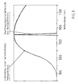
- the glare of the CCD camera is further enhanced by the use of a spectral Bandpass filter F reduced, the one shown in FIG. 3 Has transmission characteristics.
- a bandpass filter is from DE-A-40 07 646 and is not described further here.
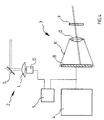
- a first embodiment of the invention represents in which the detection of a possible glare from a laser headlight of an oncoming vehicle based on the data of the video image is made.
- the known per se from DE-A-40 07 646 Laser headlight 2 comprises an emitting laser diode D, the laser beam of which a corresponding lens L and a mirror S is emitted.
- the Laser headlight 2 works, as described in DE-A-40 07 646, by the expansion of the laser beam in only one direction with simultaneous narrow focusing in the orthogonal second direction and by pivoting the illuminated flat Solid angle section in the second direction.
- the CCD camera designated 3 comprises the spectral bandpass filter F, a upstream optics O and a light-sensitive image area B, the signal of the Screen 4 is fed.
- the system checks for glare from one Laser headlights are present by the data of the video image itself through a Evaluation device 5 can be evaluated.
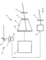
- an additional detector 6 with a narrow-band interference filter F1 is used, which then time-resolves the laser pulses and thus the clock cycles oncoming laser headlights determined.
- a timing is changed by an additional delay. This change can also be random.
- the additional detector can a free time slot can also be controlled directly. If the glare persists, the procedure is repeated in the second embodiment until no glare there is more.
- a third embodiment shown in Fig. 6, there is a fixed timing for everyone Vehicles introduced.
- the precise synchronization of all vehicles can be done by Calibrations either using a radio clock, radio telephone or GPS (Global Positioning System) can be obtained in a radio device designated 7.
- a precision from 1 ms to 5 ms is sufficient.
- An internal quartz clock makes it precise Maintain timing between calibrations.
- An electronic compass determines that Direction of travel. For a fixed directional range - e.g. between north and east, east and south, south and west, west and north - will be different Time slot used. This eliminates glare.
- a fourth embodiment several, for example three, Laser headlights with different wavelengths - 800 nm, 820 nm, 840 nm - and different bandpass filters F for these wavelengths in a filter wheel before Camera used. Furthermore, an electronic compass for determining the Direction of travel used. Depending on the direction of travel, a laser with a given one Wavelength and the associated bandpass filter of the filter wheel used.
- An electronic compass in the sense of this application is also a means understand which of tracking position information (e.g. GPS information) directional information, comparable to that of one Compass obtainable direction information.
- tracking position information e.g. GPS information
- the arrangement according to the invention can be used to present the information received by the receiving optics (3) in a manner suitable for human perception, preferably a display.
Landscapes
- Engineering & Computer Science (AREA)
- Physics & Mathematics (AREA)
- Remote Sensing (AREA)
- Computer Networks & Wireless Communication (AREA)
- General Physics & Mathematics (AREA)
- Radar, Positioning & Navigation (AREA)
- Electromagnetism (AREA)
- Lighting Device Outwards From Vehicle And Optical Signal (AREA)
- Photometry And Measurement Of Optical Pulse Characteristics (AREA)
- Road Signs Or Road Markings (AREA)
- Vehicle Interior And Exterior Ornaments, Soundproofing, And Insulation (AREA)
- Window Of Vehicle (AREA)
- Non-Portable Lighting Devices Or Systems Thereof (AREA)
Abstract
Description
Die Sichtweite mit Abblendlicht bei Gegenverkehr ist gering und wird von vielen Fahrern falsch eingeschätzt. Das führt zu einem späten Erkennen von unbeleuchteten Hindernissen, Fußgängern, Radfahrern ohne Licht und von Tieren und damit zu Unfällen.
Bei Regen, Nebel und Schneetreiben können die Sichtverhältnisse nochmals deutlich schlechter sein.
Das aus der DE-A-40 07 646 bekannte System enthält zusätzlich zu den herkömmlichen Scheinwerfern zwei "Laserscheinwerfer", die im nahen Infrarot emittierende Laserdioden als Lichtquelle nutzen. Die Laserdioden werden gepulst betrieben mit einer Pulslänge von beispielsweise 50-100 µs und einem Pulsabstand von 100-1000 µs. Damit kann eine Beleuchtung der Szene mit einem streifen- oder punktförmigen Muster erreicht werden, wodurch eine plastische Hervorhebung der beleuchteten Gegenstände wie z.B. Autos vom Straßenverlauf erzielt werden kann. Eine CCD-Kamera zur Aufnahme des Videobildes ist im Dachbereich des Fahrzeugs untergebracht. Die CCD-Kamera besitzt einen elektronischen Verschluß, der mit den Laserdioden zur Vermeidung von Störungen synchronisiert ist. Durch die Synchronisierung der CCD-Kamera mit den emittierenden Laserdioden kann sichergestellt werden, daß nur Licht aus dem von der Laserdiode beleuchteten Streifen bzw. Flächen zum Bildaufbau beiträgt und durch Mehrfachstreuung aus anderen Winkelbereichen einfallendes Licht nicht stört. Die Einzelheiten der Synchronisierung sind in der DE-A-40 07 646 beschrieben und werden zur Vermeidung von Wiederholungen weiterhin nicht ausgeführt.
Gemäß DE-A-40 07 646 wird vor dem Kameraobjektiv ein optisches Bandpaßfilter angebracht. Das Videobild wird dem Fahrer auf einem LCD-Bildschirm gezeigt. Das Verwenden von Laserlicht aus DE-A-40 07 646 hat eine Reihe von Vorteilen. Die Laser emittieren bei einer Wellenlänge von 800 bis 2000 nm, vorzugsweise 810 nm, im nahen Infrarot. Da das infrarote Licht für das menschliche Auge nahezu nicht sichtbar ist, kann permanent aufgeblendet beleuchtet werden.
Durch Verwenden von Laserlicht kann die Blendung der Kamera durch die sichtbaren Scheinwerfer entgegenkommender Fahrzeuge erheblich reduziert werden. Zum einen weist das Laserlicht nur eine spektrale Breite von wenigen nm auf, während sichtbare Lichtquellen wie Halogenlampen mehrere hundert nm breit sind. Bringt man ein optisches Bandpaßfilter mit einer schmalen Durchlaßbreite vor das Kameraobjektiv, so wird nahezu das gesamte Laserlicht ausgestrahlt, während das Licht entgegenkommender Fahrzeuge um einen Faktor 50 bis 100 geschwächt wird. Zum anderen folgen Laserdioden dem Treiberstrom unmittelbar, und sie können daher auf eine einfache Art und Weise schnell gepulst werden. Verwendet man eine Videokamera mit einem schnellen elektronischen Verschluß, der mit den Lasern synchronisiert ist, so kann das Licht entgegenkommender Fahrzeuge weiter reduziert werden.
Ein Problem ergibt sich jedoch, wenn sich zwei derartige Nachtsichtsysteme mit permanent aufgeblendeten Laserscheinwerfern begegnen. In der DE 4007646 A1 wurde dieses Problem dadurch gelöst, daß die Laserscheinwerfer aller Fahrzeuge mit der gleichen Polarisation, beispielsweise vertikaler Polarisation emittieren und vor dem Kameraobjektiv ein dazu senkrecht stehender Analysator oder Polarisator vorhanden ist.
Nachteilig bei der Verwendung von Polarisatoren und Analysatoren ist jedoch die Schwächung des von den Objekten reflektierten depolarisierten Lichts durch den Analysator, die meist den Faktor 2 bis 4 ausmacht.
Eine Vorrichtung zur blendungsfreien Führung von Fahrzeugen im Verkehr ist aus DE 2001086 C3 bekannt. Dabei wird im Sichtbereich des Fahrzeuglenkers ein Schirm mit veränderlicher Lichtdurchlässigkeit angeordnet und die Scheinwerfer sind mit Blitzlichtquellen ausgerüstet. Die Lichtdurchlässigkeit des Schirms wird durch eine Steuereinrichtung mit einer vorgegebenen Pulsfrequenz elektrisch gesteuert und zwischen nahezu vollständiger und stark reduzierter Lichtdurchlässigkeit verändert.
Aus der Schrift DE 3836095 A1 ist eine Vorrichtung zur blendungsfreien Führung von Fahrzeugen im Verkehr bekannt, bei welcher ebenfalls im Sichtbereich des Fahrzeuglenkers einen Schirm angeordnet ist, mit einer Lichtdurchlässigkeit, die durch eine Steuereinrichtung mit einer vorgegebenen Pulsfrequenz steuerbar ist. Diese Vorrichtung enthält auch Scheinwerfer zur permanenten Abstrahlung von gepulstem Infrarotlicht. Die Steuereinrichtung ist mit einem fotoelektrischen Empfänger verbunden, der so angeordnet ist, dass er von einem entgegenkommenden Fahrzeug ausgesandtes Licht als Fremdlicht auf nimmt und bei Auftreten von gepulstem Fremdlicht den Schirm und Scheinwerfer synchron und im Gegentakt zum gepulsten Fremdlicht steuert, derart, dass jeweils bei hoher Lichtemission des Fremdlichts die Lichtdurchlässigkeit des Schirms und die Lichtabgabe der Scheinwerfer reduziert werden.
Diese und weitere, der nachstehenden Beschreibung und Zeichnungen zu entnehmenden Aufgaben, werden durch eine Anordnung gemäß den anliegenden Ansprüchen gelöst.
Weitere Merkmale und Vorteile sind deutlicher der folgenden Beschreibung der bevorzugten Ausführungsbeispiele der Erfindung, unter Hinweis auf die beiliegenden Figuren zu entnehmen, wobei
Die Anzeige der erfaßten Szene erfolgt auf einem an der Armatur des Omnibusses angebrachten Bildschirm 4, der vorteilhaft mit einem ausreichenden Abstand zum Fahrer angeordnet ist, um eine Anpassung des Auges an den Bildschirm zu vermeiden, sobald der Fahrer seinen Blick von der Szene zum Bildschirm schwenkt. Ein Abstand von zirka zwei Metern wurde in der vorliegenden Ausführung für ausreichend befunden.
Die Elemente einer solchen Anordnung einer oder mehrere Optiken (2) und (3) sind hierbei die selben, wie im fahrtrichtungsabhängigen Betrieb, jedoch werden die Beleuchtungsoptiken (2) nun abhängig von deren aktuellen Beleuchtungsrichtung betrieben. Dies trägt beispielsweise den neuerdings aufkommenden in ihrer Beleuchtungsrichtung steuerbaren, also schwenkbaren Scheinwerfern Rechnung. Diese Scheinwerfer können beispielsweise in Ihrer Ausrichtung dem Kurvenverlauf von Straßen nachgeführt werden oder bei detektierten Gefahren die von Randbereichen der Fahrbahn ausgehen dorthin ausgerichtet werden. Auch trägt diese alternative Ausführungsform der Erfindung der Benutzung von Rückfahrtscheinwerfern bzw. von Suchscheinwerfern (beispielsweise in Rettungsfahrzeugen) Rechnung.
Fährt ein Fahrzeug im Rückwärtsgang, so sind die Hauptscheinwerfer des Fahrzeugs immer noch in die selbe Richtung ausgerichtet, wie bei einer Vorwärtsfahrt. Aus diesem Grunde sollte deren Betrieb auch unabhängig von der nun gegenläufigen Fahrtrichtung immer noch gleich betrieben werden, um Blendungen anderer Fahrzeuge zu vermeiden.
Auch läßt sich durch den alternative, auf den Beleuchtungsrichtung bezogenen Betrieb der Beleuchtungsoptiken die Blendung durch stehende oder parkende Fahrzeuge mit eingeschalteter Beleuchtung vermeiden.
In besonders vorteilhafter weise kann mittels der erfindungsgemäßen Anordnung die von der Empfangsoptik (3) empfangenen Information in einer für die menschliche Wahrnehmung geeigneten Weise, vorzugsweise einem Display, dargebracht werden.
Claims (11)
- Anordnung zur Verbesserung der Sicht in Fahrzeugen mit mindestens einer Beleuchtungsoptik (2) zur Abstrahlung vom infraroten gepulsten Licht und mindestens einer ihr zugeordneten Empfangsoptik (3) zum Empfang reflektierter Anteile des abgestrahlten Lichts
dadurch gekennzeichnet,
dass die Beleuchtungsoptik (2) ein Mittel zum von deren Beleuchtungsrichtung abhängigen Betrieb umfassen, wobei zur Ermittlung der dieser Beleuchtungsrichtung entsprechenden Himmelsrichtung ein Kompaß vorgesehen ist. - Anordnung nach Anspruch 1, dadurch gekennzeichnet, dass der Kompaß ein elektronischer Kompaß ist, welcher insbesondere in Verbindung mit einem Positionsbestimmungssystem oder einem Navigationsgerät steht.
- Anordnung nach einem der Ansprüche 1 oder 2, dadurch gekennzeichnet, dass die Beleuchtungsoptik (2) Teil eines Laserscheinwerfers ist, der eine in einem Bereich von 800 bis 2000 nm, vorzugsweise 810 nm, emittierende Laserdiode (D) mit einer Sendeleistung von etwa 4 Watt umfaßt, um ein infrarotes Licht mit einem Tastverhältnis zwischen 1:3 und 1:100 zu emittieren.
- Anordnung nach einem der Ansprüche 1 bis 3, dadurch gekennzeichnet, dass die Beleuchtungsoptik (2) ein Mittel zum fahrtrichtungsabhängigen Betrieb bei einem festen Zeittakt umfaßt.
- Anordnung nach Anspruch 4, dadurch gekennzeichnet, dass die Anordnung eine Funkvorrichtung (7) zum Empfang eines festen Zeittakts umfasst, wobei ein Mittel zur Auswahl des Zeittakts abhängig von der Fahrtrichtung bereitgestellt wird.
- Anordnung nach einem der Ansprüche 4 oder 5, wobei die Funkvorrichtung (7) eine Funkuhr oder ein Funktelefon oder ein globales Positionierungssystem enthält.
- Anordnung nach einem der Ansprüche 1 bis 6, dadurch gekennzeichnet, dass die Beleuchtungsoptik (2) ein Mittel zum fahrtrichtungsabhängigen Betrieb mit einer fahrtrichtungsabhängigen Wellenlänge umfaßt.
- Anordnung nach Anspruch 7, wobei die Empfangsoptik (3) ein jeder der Wellenlängen der Beleuchtungsoptik (2) entsprechendes Bandpaßfilter umfaßt und ein Mittel vorhanden ist um die Wellenlängen der Beleuchtungsoptik und die Bandpaßfilter abhängig von der Fahrtrichtung auszuwählen.
- Anordnung nach Anspruch 8, wobei die Bandpaßfilter der Empfangsoptik (3) an einem Filterrad angebracht sind.
- Anordnung einem der Ansprüche 7 bis 9, wobei die Anordnung ein Mittel umfaßt, um die Wellenlänge des von der Beleuchtungsoptik (2) emittierten gepulsten Lichts in einem Bereich um 800nm auswählen zu können.
- Anordnung nach einem der vorhergehenden Ansprüche, dadurch gekennzeichnet, dass die von der Empfangsoptik (3) empfangenen Information in einer für die menschliche Wahrnehmung geeigneten Weise, vorzugsweise einem Display, dargebracht wird.
Applications Claiming Priority (2)
| Application Number | Priority Date | Filing Date | Title |
|---|---|---|---|
| DE10002069A DE10002069C2 (de) | 2000-01-18 | 2000-01-18 | Anordnung zur Verbesserung der Sicht in Fahrzeugen |
| DE10002069 | 2000-01-18 |
Publications (3)
| Publication Number | Publication Date |
|---|---|
| EP1118877A2 true EP1118877A2 (de) | 2001-07-25 |
| EP1118877A3 EP1118877A3 (de) | 2003-11-19 |
| EP1118877B1 EP1118877B1 (de) | 2007-05-30 |
Family
ID=7627986
Family Applications (1)
| Application Number | Title | Priority Date | Filing Date |
|---|---|---|---|
| EP01100937A Expired - Lifetime EP1118877B1 (de) | 2000-01-18 | 2001-01-17 | Anordnung zur Verbesserung der Sicht in Fahrzeugen |
Country Status (5)
| Country | Link |
|---|---|
| US (1) | US6552342B2 (de) |
| EP (1) | EP1118877B1 (de) |
| JP (1) | JP2001253309A (de) |
| AT (1) | ATE363663T1 (de) |
| DE (2) | DE10002069C2 (de) |
Cited By (6)
| Publication number | Priority date | Publication date | Assignee | Title |
|---|---|---|---|---|
| WO2004050421A1 (de) * | 2002-11-29 | 2004-06-17 | Daimlerchrysler Ag | Scheinwerfer für ein fahrzeug und anordnung zur verbesserung der sicht mit solchen scheinwerfern |
| EP1544640A1 (de) * | 2003-12-16 | 2005-06-22 | DaimlerChrysler AG | Vorrichtung zur Verbesserung der Sichtverhältnisse in einem Kraftfahrzeug |
| EP1632791A3 (de) * | 2004-09-04 | 2007-05-02 | Audi Aktiengesellschaft | Nachtsichtsystem für ein Kraftfahrzeug |
| EP1647839A3 (de) * | 2004-10-18 | 2007-05-23 | Audi Ag | Verfahren und Entfernungsmessvorrichtung zum Bestimmen der Entfernung zwischen einem Objekt und der Vorrichtung |
| WO2013120152A1 (en) * | 2012-02-13 | 2013-08-22 | Gyozov Ivaylo Gerov | On board vehicle system for suppressing the dazzle effect from counter and surrounding lights |
| WO2015169408A1 (de) * | 2014-05-08 | 2015-11-12 | Audi Ag | System zur detektion von nebel direkt vor einem kraftfahrzeug |
Families Citing this family (53)
| Publication number | Priority date | Publication date | Assignee | Title |
|---|---|---|---|---|
| US7202776B2 (en) * | 1997-10-22 | 2007-04-10 | Intelligent Technologies International, Inc. | Method and system for detecting objects external to a vehicle |
| US20030193980A1 (en) * | 2001-06-05 | 2003-10-16 | Oleg Matveev | Device and method for invisible road illumination and imaging using preliminary pulses |
| US20020191388A1 (en) * | 2001-06-05 | 2002-12-19 | Oleg Matveev | Device and method for vehicular invisible road illumination and imaging |
| DE10129743C2 (de) * | 2001-06-20 | 2003-05-08 | Daimler Chrysler Ag | Fahrzeugscheinwerfer, mit einer Anzahl von elektronischen Leuchtelementen als Lichtquelle |
| DE10131840A1 (de) * | 2001-06-30 | 2003-01-23 | Daimler Chrysler Ag | Vorrichtung zur Verbesserung der Sicht in Fahrzeugen |
| US20040252993A1 (en) * | 2002-04-05 | 2004-12-16 | Hidenori Sato | Camera built-in mirror equipment |
| US6828544B2 (en) * | 2002-06-12 | 2004-12-07 | Ford Global Technologies, Llc | Active night vision system for vehicles employing anti-blinding scheme |
| US6900437B2 (en) * | 2002-06-12 | 2005-05-31 | Ford Global Technologies, Llc | Color corrected laser illumination system for night vision applications |
| US7683326B2 (en) * | 2002-07-09 | 2010-03-23 | Gentex Corporation | Vehicle vision system with high dynamic range |
| DE10303047A1 (de) * | 2003-01-24 | 2004-08-05 | Daimlerchrysler Ag | Verfahren und Vorrichtung zur Sichtverbesserung und zur Bestimmung der Wettersituation |
| DE10305009A1 (de) * | 2003-02-07 | 2004-09-02 | Robert Bosch Gmbh | Vorrichtung und Verfahren zur Bilderzeugung |
| US20040263346A1 (en) * | 2003-06-27 | 2004-12-30 | Guide Corporation, A Delaware Corporation | Solid state adaptive forward lighting system |
| FR2858277B1 (fr) * | 2003-08-01 | 2006-02-17 | Valeo Vision | Moyens de detection de virage integrables dans un dispositif de controle d'un systeme d'eclairage a fonction virage |
| DE10341671A1 (de) * | 2003-09-08 | 2005-04-07 | Conti Temic Microelectronic Gmbh | Umgebungsüberwachungssystem mit Nachtsichteinheit und Entfernungsmesseinheit |
| US7012551B2 (en) * | 2004-02-04 | 2006-03-14 | Ford Global Technologies, Llc | Method of anti-blinding for active night vision system |
| US7586079B2 (en) * | 2005-05-13 | 2009-09-08 | Dynamic Eye, Inc. | Low power glare sensor |
| DE102005027006A1 (de) * | 2005-06-10 | 2006-12-28 | Siemens Ag | Infrarot-Sichteinrichtung |
| JP2007076429A (ja) * | 2005-09-13 | 2007-03-29 | Koito Mfg Co Ltd | ヘッドランプシステム |
| DE102006013700B3 (de) * | 2006-03-24 | 2007-10-11 | Robert Bosch Gmbh | Einrichtung an einem Fahrzeug zur Verhinderung der Blendung |
| JP2007264932A (ja) * | 2006-03-28 | 2007-10-11 | Kyocera Corp | 車両用通信システムおよび車載用撮像装置 |
| JP4620640B2 (ja) * | 2006-07-25 | 2011-01-26 | パナソニック株式会社 | ヘッドライトモジュール |
| DE102007004348A1 (de) | 2007-01-29 | 2008-07-31 | Robert Bosch Gmbh | Imager-Halbleiterbauelement, Kamerasystem und Verfahren zum Erstellen eines Bildes |
| DE102007004349A1 (de) | 2007-01-29 | 2008-07-31 | Robert Bosch Gmbh | Nachtsichtsystem, insbesondere für ein Fahrzeug, und Verfahren zum Erstellen eines Nachtsichtbildes |
| DE102007049637B4 (de) * | 2007-10-17 | 2015-10-15 | Audi Ag | Verfahren zum Betreiben eines Leuchtsystems und eines Bilderfassungssystems eines Fahrzeugs sowie Objekterfassungssystem für ein Fahrzeug |
| JP2010179890A (ja) * | 2009-02-09 | 2010-08-19 | Asahi Denso Co Ltd | ターンシグナルスイッチ装置 |
| US20130083195A1 (en) * | 2011-09-30 | 2013-04-04 | Jeffrey Thomas Remillard | Polarization-based anti-blinding night vision system, vehicle comprising same, and method therefor |
| KR20130047214A (ko) * | 2011-10-31 | 2013-05-08 | 현대자동차주식회사 | 스팟 램프유닛, 상기 스팟 램프유닛이 구비된 헤드라이트 시스템 및 이를 이용한 전방 조명방법 |
| CN103295349A (zh) * | 2012-03-01 | 2013-09-11 | 北京威斯顿亚太光电仪器有限公司 | 雨雾天高速路报警器 |
| CN103434369A (zh) * | 2013-08-28 | 2013-12-11 | 吴云肖 | 强光抑制装置及夜间会车强光抑制系统及方法 |
| US9654703B2 (en) * | 2014-09-08 | 2017-05-16 | Nxp B.V. | Illumination apparatus |
| DE102015212365A1 (de) * | 2015-07-02 | 2017-01-05 | Conti Temic Microelectronic Gmbh | Synchronisation einer Belichtung einer Kamera |
| JP6602683B2 (ja) * | 2016-02-05 | 2019-11-06 | 株式会社東芝 | 充電装置および位置ずれ検出方法 |
| JP6645254B2 (ja) * | 2016-02-23 | 2020-02-14 | 株式会社デンソー | 物体認識装置 |
| TWI607911B (zh) * | 2016-04-28 | 2017-12-11 | H P B Optoelectronic Co Ltd | Vehicle safety protection system and method |
| CN106183738B (zh) * | 2016-07-21 | 2019-06-25 | 吴云肖 | 一种基于分区挡片的会车强光抑制装置及系统 |
| JP6809946B2 (ja) * | 2017-03-17 | 2021-01-06 | トヨタ自動車株式会社 | 車両用前照灯装置 |
| US10334331B2 (en) | 2017-08-25 | 2019-06-25 | Honda Motor Co., Ltd. | System and method for synchronized vehicle sensor data acquisition processing using vehicular communication |
| US10757485B2 (en) | 2017-08-25 | 2020-08-25 | Honda Motor Co., Ltd. | System and method for synchronized vehicle sensor data acquisition processing using vehicular communication |
| US10168418B1 (en) | 2017-08-25 | 2019-01-01 | Honda Motor Co., Ltd. | System and method for avoiding sensor interference using vehicular communication |
| DE112018005039T5 (de) * | 2017-09-11 | 2020-07-23 | Sony Corporation | Signalverarbeitungsvorrichtung, signalverarbeitungsverfahren, programm und mobiler körper |
| US11181929B2 (en) | 2018-07-31 | 2021-11-23 | Honda Motor Co., Ltd. | System and method for shared autonomy through cooperative sensing |
| US11163317B2 (en) | 2018-07-31 | 2021-11-02 | Honda Motor Co., Ltd. | System and method for shared autonomy through cooperative sensing |
| DE102018222701A1 (de) * | 2018-12-21 | 2020-06-25 | Robert Bosch Gmbh | Sensoreinrichtung und Verfahren zum Betreiben einer Sensoreinrichtung für ein Fahrzeug |
| CN110285947B (zh) * | 2019-02-20 | 2020-11-27 | 北京工业大学 | 一种隧道照明的交通安全眩光的测算方法 |
| US11396986B2 (en) | 2019-05-23 | 2022-07-26 | Valeo North America, Inc. | Apparatus and method for masking residual visible light from an infrared emission source |
| US11465561B2 (en) | 2020-04-17 | 2022-10-11 | Magna Mirrors Of America, Inc. | Interior rearview mirror assembly with driver monitoring system |
| US11972597B2 (en) | 2021-02-09 | 2024-04-30 | Magna Electronics Inc. | Vehicular driver monitoring system with camera view optimization |
| US12447899B2 (en) | 2021-03-01 | 2025-10-21 | Magna Mirror of America, Inc. | Vehicular cabin monitoring system with camera and near IR light emitter at interior rearview mirror assembly |
| US11639134B1 (en) | 2021-03-01 | 2023-05-02 | Magna Mirrors Of America, Inc. | Interior rearview mirror assembly with driver monitoring system |
| US11827153B2 (en) | 2021-09-03 | 2023-11-28 | Magna Electronics Inc. | Vehicular interior cabin lighting system selectively operable for DMS and OMS functions |
| US12333770B2 (en) | 2022-05-13 | 2025-06-17 | Magna Electronics Inc. | Vehicular camera with polarization filter |
| US12134358B2 (en) | 2022-05-16 | 2024-11-05 | Magna Mirrors Of America, Inc. | Vehicular driver monitoring system |
| DE102023212939A1 (de) | 2023-01-01 | 2024-07-04 | Magna Mirrors Of America, Inc. | System zur überwachung eines fahrers eines fahrzeugs |
Family Cites Families (9)
| Publication number | Priority date | Publication date | Assignee | Title |
|---|---|---|---|---|
| DE483263C (de) * | 1924-07-01 | 1929-10-02 | Karl Dumas Chambers | Verfahren und Vorrichtung zur Verhinderung der Scheinwerferblendung, insbesondere bei sich entgegenkommenden Fahrzeugen |
| DE918187C (de) * | 1950-11-16 | 1954-09-20 | Svenska Aeroplan Aktiebolaget | Blendschutzvorrichtung fuer Fahrzeuge |
| DE2001086C3 (de) * | 1970-01-12 | 1980-11-06 | Siemens Ag, 1000 Berlin U. 8000 Muenchen | Vorrichtung zur blendungsfreien Fahrzeugbeleuchtung |
| DE3826095A1 (de) | 1988-08-01 | 1990-02-08 | Werner & Pfleiderer | Vorrichtung zur entnahme von schmelze-proben aus einem bei erhoehter temperatur fluessigen, bei umgebungstemperatur jedoch festen material |
| DE3836095A1 (de) * | 1988-10-22 | 1990-04-26 | Bosch Gmbh Robert | Vorrichtung zur blendungsfreien fuehrung von fahrzeugen im verkehr |
| DE4042730B4 (de) * | 1990-03-10 | 2007-10-11 | Daimlerchrysler Ag | Anordnung zur Verbesserung der Sicht in Fahrzeugen |
| DE4032927A1 (de) * | 1990-10-17 | 1992-04-30 | Bosch Gmbh Robert | Vorrichtung zur verbesserung der sichtverhaeltnisse in einem kraftfahrzeug |
| US6150930A (en) * | 1992-08-14 | 2000-11-21 | Texas Instruments Incorporated | Video equipment and method to assist motor vehicle operators |
| US5285060A (en) * | 1992-12-15 | 1994-02-08 | Donnelly Corporation | Display for automatic rearview mirror |
-
2000
- 2000-01-18 DE DE10002069A patent/DE10002069C2/de not_active Expired - Fee Related
-
2001
- 2001-01-17 DE DE50112536T patent/DE50112536D1/de not_active Expired - Lifetime
- 2001-01-17 AT AT01100937T patent/ATE363663T1/de not_active IP Right Cessation
- 2001-01-17 EP EP01100937A patent/EP1118877B1/de not_active Expired - Lifetime
- 2001-01-18 US US09/765,216 patent/US6552342B2/en not_active Expired - Lifetime
- 2001-01-18 JP JP2001010700A patent/JP2001253309A/ja not_active Ceased
Cited By (6)
| Publication number | Priority date | Publication date | Assignee | Title |
|---|---|---|---|---|
| WO2004050421A1 (de) * | 2002-11-29 | 2004-06-17 | Daimlerchrysler Ag | Scheinwerfer für ein fahrzeug und anordnung zur verbesserung der sicht mit solchen scheinwerfern |
| EP1544640A1 (de) * | 2003-12-16 | 2005-06-22 | DaimlerChrysler AG | Vorrichtung zur Verbesserung der Sichtverhältnisse in einem Kraftfahrzeug |
| EP1632791A3 (de) * | 2004-09-04 | 2007-05-02 | Audi Aktiengesellschaft | Nachtsichtsystem für ein Kraftfahrzeug |
| EP1647839A3 (de) * | 2004-10-18 | 2007-05-23 | Audi Ag | Verfahren und Entfernungsmessvorrichtung zum Bestimmen der Entfernung zwischen einem Objekt und der Vorrichtung |
| WO2013120152A1 (en) * | 2012-02-13 | 2013-08-22 | Gyozov Ivaylo Gerov | On board vehicle system for suppressing the dazzle effect from counter and surrounding lights |
| WO2015169408A1 (de) * | 2014-05-08 | 2015-11-12 | Audi Ag | System zur detektion von nebel direkt vor einem kraftfahrzeug |
Also Published As
| Publication number | Publication date |
|---|---|
| US6552342B2 (en) | 2003-04-22 |
| DE10002069A1 (de) | 2001-08-09 |
| DE50112536D1 (de) | 2007-07-12 |
| US20010050340A1 (en) | 2001-12-13 |
| EP1118877B1 (de) | 2007-05-30 |
| DE10002069C2 (de) | 2002-01-24 |
| ATE363663T1 (de) | 2007-06-15 |
| EP1118877A3 (de) | 2003-11-19 |
| JP2001253309A (ja) | 2001-09-18 |
Similar Documents
| Publication | Publication Date | Title |
|---|---|---|
| EP1118877B1 (de) | Anordnung zur Verbesserung der Sicht in Fahrzeugen | |
| DE10126492B4 (de) | Verfahren zur Verbesserung der Sicht in Fahrzeugen | |
| DE4317772C2 (de) | Blendlichtsensor für Fahrzeuge | |
| DE69110752T2 (de) | Beleuchtungs- und Anzeigesystem für Fahrzeuge. | |
| DE60319238T2 (de) | Nachtsichtabbildungssystem und -Verfahren zur Montage in einem Fahrzeug | |
| DE69618192T2 (de) | Fahrzeug-rückblicksystem mit panoramischer sicht | |
| DE10129743C2 (de) | Fahrzeugscheinwerfer, mit einer Anzahl von elektronischen Leuchtelementen als Lichtquelle | |
| DE69331638T2 (de) | Eine spiegelmontageanordnung mit der fähigkeit einen bestimmten engen lichtstrahl zu senden oder zu empfangen | |
| DE69418868T2 (de) | Spiegelanordnung | |
| EP1194805B1 (de) | Bilddarstellungssystem und -verfahren für fahrzeuge | |
| EP1668386B1 (de) | Verfahren zur verbesserung der sicht in einem kraftfahrzeug | |
| EP1022190A2 (de) | Rückspiegel | |
| DE10007984A9 (de) | Leuchtvorrichtung für Fahrzeuge | |
| EP1160506A2 (de) | Scheinwerfer für Fahrzeuge nach dem Projektionsprinzip und Beleuchtungseinrichtug mit wenigstens einem solchen Scheinwerfer | |
| DE102018102575B4 (de) | Intelligentes Multifunktions-Kraftfahrzeugscheinwerfermodul | |
| DE4007646A1 (de) | Anordnung zur verbesserung der sicht in fahrzeugen | |
| DE4107850A1 (de) | Anordnung zur verbesserung der sicht, insbesondere in fahrzeugen | |
| DE102009020910A1 (de) | Scheinwerfersystem für ein Fahrzeug mit einem Bildgeber | |
| DE102017218683A1 (de) | Fahrzeugbasiertes Lidar-System | |
| DE10354714B4 (de) | Fahrzeugscheinwerfer und Verfahren zum Betreiben eines Fahrzeugscheinwerfers | |
| EP1282097A2 (de) | Verfahren zur Verbesserung der Sicht in Fahrzeugen | |
| DE212013000187U1 (de) | System Abbildung einer Aussenszene durch Verwendung eines anwendungsspezifischen Bildsensors | |
| EP1565346B1 (de) | Breitbandige beleuchtungseinrichtung | |
| DE102007049877A1 (de) | Sensormodul und Betriebsverfahren hierfür | |
| WO2003008232A1 (de) | Umgebungsdetektionsvorrichtung und umgebungsdetektionsverfahren zur detektion eines umgebungsbereichs eines kraftfahrzeugs |
Legal Events
| Date | Code | Title | Description |
|---|---|---|---|
| PUAI | Public reference made under article 153(3) epc to a published international application that has entered the european phase |
Free format text: ORIGINAL CODE: 0009012 |
|
| AK | Designated contracting states |
Kind code of ref document: A2 Designated state(s): AT BE CH CY DE DK ES FI FR GB GR IE IT LI LU MC NL PT SE TR |
|
| AX | Request for extension of the european patent |
Free format text: AL;LT;LV;MK;RO;SI |
|
| PUAL | Search report despatched |
Free format text: ORIGINAL CODE: 0009013 |
|
| AK | Designated contracting states |
Kind code of ref document: A3 Designated state(s): AT BE CH CY DE DK ES FI FR GB GR IE IT LI LU MC NL PT SE TR |
|
| AX | Request for extension of the european patent |
Extension state: AL LT LV MK RO SI |
|
| 17P | Request for examination filed |
Effective date: 20040511 |
|
| AKX | Designation fees paid |
Designated state(s): AT BE CH CY DE DK ES FI FR GB GR IE IT LI LU MC NL PT SE TR |
|
| GRAP | Despatch of communication of intention to grant a patent |
Free format text: ORIGINAL CODE: EPIDOSNIGR1 |
|
| GRAS | Grant fee paid |
Free format text: ORIGINAL CODE: EPIDOSNIGR3 |
|
| RAP1 | Party data changed (applicant data changed or rights of an application transferred) |
Owner name: DAIMLERCHRYSLER AG |
|
| GRAA | (expected) grant |
Free format text: ORIGINAL CODE: 0009210 |
|
| AK | Designated contracting states |
Kind code of ref document: B1 Designated state(s): AT BE CH CY DE DK ES FI FR GB GR IE IT LI LU MC NL PT SE TR |
|
| PG25 | Lapsed in a contracting state [announced via postgrant information from national office to epo] |
Ref country code: FI Free format text: LAPSE BECAUSE OF FAILURE TO SUBMIT A TRANSLATION OF THE DESCRIPTION OR TO PAY THE FEE WITHIN THE PRESCRIBED TIME-LIMIT Effective date: 20070530 |
|
| REG | Reference to a national code |
Ref country code: GB Ref legal event code: FG4D Free format text: NOT ENGLISH |
|
| REG | Reference to a national code |
Ref country code: CH Ref legal event code: EP |
|
| REG | Reference to a national code |
Ref country code: IE Ref legal event code: FG4D Free format text: LANGUAGE OF EP DOCUMENT: GERMAN |
|
| REF | Corresponds to: |
Ref document number: 50112536 Country of ref document: DE Date of ref document: 20070712 Kind code of ref document: P |
|
| GBT | Gb: translation of ep patent filed (gb section 77(6)(a)/1977) |
Effective date: 20070704 |
|
| PG25 | Lapsed in a contracting state [announced via postgrant information from national office to epo] |
Ref country code: SE Free format text: LAPSE BECAUSE OF FAILURE TO SUBMIT A TRANSLATION OF THE DESCRIPTION OR TO PAY THE FEE WITHIN THE PRESCRIBED TIME-LIMIT Effective date: 20070830 |
|
| PG25 | Lapsed in a contracting state [announced via postgrant information from national office to epo] |
Ref country code: ES Free format text: LAPSE BECAUSE OF FAILURE TO SUBMIT A TRANSLATION OF THE DESCRIPTION OR TO PAY THE FEE WITHIN THE PRESCRIBED TIME-LIMIT Effective date: 20070910 |
|
| ET | Fr: translation filed | ||
| NLV1 | Nl: lapsed or annulled due to failure to fulfill the requirements of art. 29p and 29m of the patents act | ||
| RAP2 | Party data changed (patent owner data changed or rights of a patent transferred) |
Owner name: DAIMLER AG |
|
| REG | Reference to a national code |
Ref country code: IE Ref legal event code: FD4D |
|
| PG25 | Lapsed in a contracting state [announced via postgrant information from national office to epo] |
Ref country code: IE Free format text: LAPSE BECAUSE OF FAILURE TO SUBMIT A TRANSLATION OF THE DESCRIPTION OR TO PAY THE FEE WITHIN THE PRESCRIBED TIME-LIMIT Effective date: 20070530 Ref country code: PT Free format text: LAPSE BECAUSE OF FAILURE TO SUBMIT A TRANSLATION OF THE DESCRIPTION OR TO PAY THE FEE WITHIN THE PRESCRIBED TIME-LIMIT Effective date: 20071030 Ref country code: NL Free format text: LAPSE BECAUSE OF FAILURE TO SUBMIT A TRANSLATION OF THE DESCRIPTION OR TO PAY THE FEE WITHIN THE PRESCRIBED TIME-LIMIT Effective date: 20070530 Ref country code: DK Free format text: LAPSE BECAUSE OF FAILURE TO SUBMIT A TRANSLATION OF THE DESCRIPTION OR TO PAY THE FEE WITHIN THE PRESCRIBED TIME-LIMIT Effective date: 20070530 |
|
| PLBE | No opposition filed within time limit |
Free format text: ORIGINAL CODE: 0009261 |
|
| STAA | Information on the status of an ep patent application or granted ep patent |
Free format text: STATUS: NO OPPOSITION FILED WITHIN TIME LIMIT |
|
| PG25 | Lapsed in a contracting state [announced via postgrant information from national office to epo] |
Ref country code: GR Free format text: LAPSE BECAUSE OF FAILURE TO SUBMIT A TRANSLATION OF THE DESCRIPTION OR TO PAY THE FEE WITHIN THE PRESCRIBED TIME-LIMIT Effective date: 20070831 Ref country code: IT Free format text: LAPSE BECAUSE OF FAILURE TO SUBMIT A TRANSLATION OF THE DESCRIPTION OR TO PAY THE FEE WITHIN THE PRESCRIBED TIME-LIMIT Effective date: 20070530 |
|
| 26N | No opposition filed |
Effective date: 20080303 |
|
| BERE | Be: lapsed |
Owner name: DAIMLERCHRYSLER A.G. Effective date: 20080131 |
|
| PG25 | Lapsed in a contracting state [announced via postgrant information from national office to epo] |
Ref country code: MC Free format text: LAPSE BECAUSE OF NON-PAYMENT OF DUE FEES Effective date: 20080131 |
|
| REG | Reference to a national code |
Ref country code: CH Ref legal event code: PL |
|
| PG25 | Lapsed in a contracting state [announced via postgrant information from national office to epo] |
Ref country code: CH Free format text: LAPSE BECAUSE OF NON-PAYMENT OF DUE FEES Effective date: 20080131 Ref country code: LI Free format text: LAPSE BECAUSE OF NON-PAYMENT OF DUE FEES Effective date: 20080131 |
|
| PG25 | Lapsed in a contracting state [announced via postgrant information from national office to epo] |
Ref country code: BE Free format text: LAPSE BECAUSE OF NON-PAYMENT OF DUE FEES Effective date: 20080131 |
|
| REG | Reference to a national code |
Ref country code: FR Ref legal event code: CD |
|
| PG25 | Lapsed in a contracting state [announced via postgrant information from national office to epo] |
Ref country code: AT Free format text: LAPSE BECAUSE OF NON-PAYMENT OF DUE FEES Effective date: 20080117 |
|
| PG25 | Lapsed in a contracting state [announced via postgrant information from national office to epo] |
Ref country code: CY Free format text: LAPSE BECAUSE OF FAILURE TO SUBMIT A TRANSLATION OF THE DESCRIPTION OR TO PAY THE FEE WITHIN THE PRESCRIBED TIME-LIMIT Effective date: 20070530 |
|
| PG25 | Lapsed in a contracting state [announced via postgrant information from national office to epo] |
Ref country code: LU Free format text: LAPSE BECAUSE OF NON-PAYMENT OF DUE FEES Effective date: 20080117 |
|
| PG25 | Lapsed in a contracting state [announced via postgrant information from national office to epo] |
Ref country code: TR Free format text: LAPSE BECAUSE OF FAILURE TO SUBMIT A TRANSLATION OF THE DESCRIPTION OR TO PAY THE FEE WITHIN THE PRESCRIBED TIME-LIMIT Effective date: 20070530 |
|
| PGFP | Annual fee paid to national office [announced via postgrant information from national office to epo] |
Ref country code: FR Payment date: 20110615 Year of fee payment: 11 |
|
| PGFP | Annual fee paid to national office [announced via postgrant information from national office to epo] |
Ref country code: GB Payment date: 20110531 Year of fee payment: 11 |
|
| PGFP | Annual fee paid to national office [announced via postgrant information from national office to epo] |
Ref country code: DE Payment date: 20110527 Year of fee payment: 11 |
|
| GBPC | Gb: european patent ceased through non-payment of renewal fee |
Effective date: 20120117 |
|
| REG | Reference to a national code |
Ref country code: FR Ref legal event code: ST Effective date: 20120928 |
|
| PG25 | Lapsed in a contracting state [announced via postgrant information from national office to epo] |
Ref country code: DE Free format text: LAPSE BECAUSE OF NON-PAYMENT OF DUE FEES Effective date: 20120801 Ref country code: GB Free format text: LAPSE BECAUSE OF NON-PAYMENT OF DUE FEES Effective date: 20120117 |
|
| REG | Reference to a national code |
Ref country code: DE Ref legal event code: R119 Ref document number: 50112536 Country of ref document: DE Effective date: 20120801 |
|
| PG25 | Lapsed in a contracting state [announced via postgrant information from national office to epo] |
Ref country code: FR Free format text: LAPSE BECAUSE OF NON-PAYMENT OF DUE FEES Effective date: 20120131 |