EP1119008A2 - Membranschalter - Google Patents
Membranschalter Download PDFInfo
- Publication number
- EP1119008A2 EP1119008A2 EP01100139A EP01100139A EP1119008A2 EP 1119008 A2 EP1119008 A2 EP 1119008A2 EP 01100139 A EP01100139 A EP 01100139A EP 01100139 A EP01100139 A EP 01100139A EP 1119008 A2 EP1119008 A2 EP 1119008A2
- Authority
- EP
- European Patent Office
- Prior art keywords
- wall
- button
- housing
- membrane
- guide
- Prior art date
- Legal status (The legal status is an assumption and is not a legal conclusion. Google has not performed a legal analysis and makes no representation as to the accuracy of the status listed.)
- Granted
Links
Images

Classifications
-
- H—ELECTRICITY
- H01—ELECTRIC ELEMENTS
- H01H—ELECTRIC SWITCHES; RELAYS; SELECTORS; EMERGENCY PROTECTIVE DEVICES
- H01H13/00—Switches having rectilinearly-movable operating part or parts adapted for pushing or pulling in one direction only, e.g. push-button switch
- H01H13/02—Details
- H01H13/12—Movable parts; Contacts mounted thereon
- H01H13/14—Operating parts, e.g. push-button
-
- H—ELECTRICITY
- H01—ELECTRIC ELEMENTS
- H01H—ELECTRIC SWITCHES; RELAYS; SELECTORS; EMERGENCY PROTECTIVE DEVICES
- H01H13/00—Switches having rectilinearly-movable operating part or parts adapted for pushing or pulling in one direction only, e.g. push-button switch
- H01H13/02—Details
- H01H13/04—Cases; Covers
-
- H—ELECTRICITY
- H01—ELECTRIC ELEMENTS
- H01H—ELECTRIC SWITCHES; RELAYS; SELECTORS; EMERGENCY PROTECTIVE DEVICES
- H01H1/00—Contacts
- H01H1/58—Electric connections to or between contacts; Terminals
- H01H1/5866—Electric connections to or between contacts; Terminals characterised by the use of a plug and socket connector
-
- H—ELECTRICITY
- H01—ELECTRIC ELEMENTS
- H01H—ELECTRIC SWITCHES; RELAYS; SELECTORS; EMERGENCY PROTECTIVE DEVICES
- H01H13/00—Switches having rectilinearly-movable operating part or parts adapted for pushing or pulling in one direction only, e.g. push-button switch
- H01H13/02—Details
- H01H13/023—Light-emitting indicators
Definitions
- the invention relates to a membrane key switch with a housing and a key that is slidably guided on the housing.
- Modern membrane pushbutton switches as used in particular in motor vehicles are used, are short-stroke and have an illuminable if necessary Keypad. They consist of a plastic housing and a key attached to it and guided. Located below the button there is a connector chamber in which a generally multi-pin connector is used and locked. The connector chamber takes a large one Part of the generally specified total height of the switch, which means that there is little overall height for guiding the button.
- the invention provides a membrane push button switch, where the key guide extends over almost the entire height of the switch can extend.
- the housing has an outer wall that extends up to extends to a base surface facing away from the key, on the Base is angled inwards and into a parallel to the outer wall angled inner wall merges, which forms a plug chamber;
- the button has at least one molded guide wall, which between the inner wall and the outer wall of the housing is arranged.
- the Guide wall of the key thus surrounds the connector chamber, so that the height the plug chamber is not a limitation on the length of the button guide. In the preferred embodiment, therefore, the Guide wall of the key close to the base of the housing.
- a further improvement of the key guide is the preferred Embodiment achieved in that the inside of the outer wall of the Housing and on the outside on the guide wall of the button guide ribs and corresponding guide channels are formed.
- the inner wall of the housing at its end facing the button into an angled upper Wall over.
- a circuit board can be placed between the button and the top wall be arranged on the functional elements of the membrane switch are constructed, in particular one which can be actuated by means of the key Membrane switch element and an optional illuminated switch symbol.
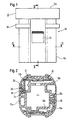
- the membrane key switch shown in the figures has a housing 10 made of plastic, the shape of which is generally cylindrical, with a Cross-sectional shape that resembles a rectangle with rounded corners.
- a button 12 also made of plastic, is arranged on the housing 10.
- the key 12 has a key surface 12a and an integral part Guide wall 12b.
- the housing 10 consists of an outer wall 10a, which is located between an upper button 12 facing Edge and a base extends and angled in there is, an inner wall 10b, which is from the inwardly angled area the outer wall 10a goes out and parallel to the outer wall in the direction the button 12 extends, and an upper wall 10c which is parallel to the Touch surface 12a is. All components of the housing 10, outer wall 10a, Inner wall 10b and upper wall 10c are integrally formed with one another, especially by injection molding.
- the inner wall 10b of the housing delimits with the upper wall 10c, a connector chamber 14, into the contact pins 16 protrude.
- the contact pins 16 penetrate the upper one Wall 10c and are connected to a circuit board 18 which between the button 12 and the upper wall 10c of the housing parallel to this is arranged.
- Various functional elements are on the printed circuit board 18 membrane switch. This includes switch contacts, Lighting elements, electronic components and the like. Between the button 12 and the circuit board 18 are optical and mechanical transmission elements.
- the outer wall 10a and the inner wall 10b of the housing 10 have one radial distance from each other.
- the guide wall 12b Key 12 inserted in the so between the outer wall 10 a and The inner wall 10b formed intermediate space.
- This guide wall 12b extends between Outer wall 10a and inner wall 10b close to the base 10d of the Housing 10, where the inner wall and outer wall are connected.
- the distance a between the end of the guide wall 12b and the base the housing 10 is slightly larger than the intended key travel.
- Further guide ribs 30, 32 are on the Molded outside of the guide wall 12b and extend vertically to the guide ribs 20 and 28 so that the button 12 in two directions perpendicular to one another and perpendicular to their axis largely is supported without play. Furthermore, a rib 22 is on the inside the outer wall 10a integrally formed and serves as an anti-rotation device in the Installation of the button 12.
- latching arms 34 integrally formed, by means of which the membrane key switch in one Opening an aperture 36 or the like is locked.
- a circumferential Support collar 38 formed on the outside of the outer wall 10a. With this Support collar 38 is the axial position of the housing 10 on the Aperture 36 set.
- Lugs 40 are formed on the inside of the outer wall 10a into corresponding recesses 42 in the guide wall 12b of the button 12 intervene to the key with that required for the key stroke Lock game on the housing 10.
Landscapes
- Push-Button Switches (AREA)
- Switch Cases, Indication, And Locking (AREA)
Abstract
Description
- Figur 1
- schematisch eine Seitenansicht des Membran-Tastschalters;
- Figur 2
- einen Schnitt entlang Linie II - II in Figur 1; und
- Figur 3
- einen Schnitt entlang Linie III - III in Figur 1.
Claims (6)
- Membran-Tastschalter mit einem Gehäuse (10) und einer an dem Gehäuse (10) verschiebbar geführten Taste (12), dadurch gekennzeichnet, daß das Gehäuse (10) eine Außenwand (10a) aufweist, die sich bis zu einer von der Taste (12) abgewandten Grundfläche erstreckt, an der Grundfläche einwärts abgewinkelt ist und in eine parallel zur Außenwand (10a) abgewinkelte Innenwand (10b) übergeht, die eine Steckerkammer (14) bildet, und daß die Taste (12) wenigstens eine angeformte Führungswand (12b) aufweist, die zwischen der Innenwand (10b) und der Außenwand (10a) des Gehäuses (10) angeordnet ist.
- Membran-Tastschalter nach Anspruch 1, dadurch gekennzeichnet, daß sich die Führungswand (12b) der Taste (12) bis nahe an die Grundfläche erstreckt.
- Membran-Tastschalter nach Anspruch 1 oder 2, dadurch gekennzeichnet, daß innenseitig an der Außenwand (10a) des Gehäuses (10) und außenseitig an der Führungswand (12b) der Taste (12) Führungsrippen (30,32) und entsprechende Führungskanäle angeformt sind.
- Membran-Tastschalter nach einem der vorstehenden Ansprüche, dadurch gekennzeichnet, daß die Innenwand (10b) des Gehäuses (10) an ihrem der Taste (12) zugewandten Ende in eine abgewinkelte obere Wand (10c) übergeht.
- Membran-Tastschalter nach Anspruch 4, dadurch gekennzeichnet, daß zwischen der Taste (12) und der oberen Wand (10c) and eine Leiterplatte (18) angeordnet ist, auf der Funktionselemente des Membran-Tastschalters, insbesondere ein mittels der Taste (12) betätigbares Membran-Schalterelement und ein optionales beleuchtbares Schaltersymbol, aufgebaut sind.
- Membran-Tastschalter nach Anspruch 5, dadurch gekennzeichnet, daß Kontaktstifte (16) von der Leiterplatte (18) ausgehend die obere Wand (10c) durchqueren und in die Steckerkammer (14) hineinragen.
Applications Claiming Priority (2)
| Application Number | Priority Date | Filing Date | Title |
|---|---|---|---|
| DE20001024U | 2000-01-21 | ||
| DE20001024U DE20001024U1 (de) | 2000-01-21 | 2000-01-21 | Membranschalter |
Publications (3)
| Publication Number | Publication Date |
|---|---|
| EP1119008A2 true EP1119008A2 (de) | 2001-07-25 |
| EP1119008A3 EP1119008A3 (de) | 2003-08-06 |
| EP1119008B1 EP1119008B1 (de) | 2007-02-21 |
Family
ID=7936207
Family Applications (1)
| Application Number | Title | Priority Date | Filing Date |
|---|---|---|---|
| EP01100139A Expired - Lifetime EP1119008B1 (de) | 2000-01-21 | 2001-01-15 | Membranschalter |
Country Status (9)
| Country | Link |
|---|---|
| US (1) | US6333478B1 (de) |
| EP (1) | EP1119008B1 (de) |
| JP (1) | JP2001250447A (de) |
| KR (1) | KR20010076334A (de) |
| CN (1) | CN1170295C (de) |
| BR (1) | BRPI0100111B1 (de) |
| CZ (1) | CZ2001246A3 (de) |
| DE (2) | DE20001024U1 (de) |
| ES (1) | ES2160558T1 (de) |
Families Citing this family (6)
| Publication number | Priority date | Publication date | Assignee | Title |
|---|---|---|---|---|
| DE10130251C1 (de) * | 2001-06-22 | 2002-11-21 | Audi Ag | Drucktastenschaltergehäuse und Drucktastenschalter |
| JP2005209506A (ja) * | 2004-01-23 | 2005-08-04 | Calsonic Kansei Corp | 車載用押しボタンスイッチ |
| ITVR20040040U1 (it) * | 2004-12-10 | 2005-03-10 | Vemer Siber Group S P A | Interruttore |
| US7592559B2 (en) * | 2005-04-28 | 2009-09-22 | Trw Automotive U.S. Llc | Bezel and actuator |
| KR101956432B1 (ko) * | 2016-11-03 | 2019-03-08 | 현대자동차주식회사 | 터치입력장치 |
| CN111508751B (zh) * | 2020-04-30 | 2023-04-14 | 合肥联宝信息技术有限公司 | 一种按键机构及电子设备 |
Family Cites Families (14)
| Publication number | Priority date | Publication date | Assignee | Title |
|---|---|---|---|---|
| DE2848103C2 (de) * | 1978-11-06 | 1980-07-31 | Fa. Leopold Kostal, 5880 Luedenscheid | Mit Bedientaste ausgestatteter optoelektronischer Schalter, insbesondere für Kraftfahrzeuge |
| FR2503446B1 (fr) * | 1981-04-02 | 1984-05-25 | Secme | Commutateur miniature notamment pour circuit imprime |
| JPH0495319A (ja) * | 1990-08-03 | 1992-03-27 | Alps Electric Co Ltd | 押釦スイツチ |
| JP3146595B2 (ja) * | 1992-02-04 | 2001-03-19 | ソニー株式会社 | 電子機器のスイッチ装置 |
| DE4316998A1 (de) | 1993-05-21 | 1994-11-24 | Eaton Controls Gmbh | Elektrischer Drucktastenschalter |
| DE9403910U1 (de) | 1994-03-08 | 1994-05-11 | Wang, Cheng-Hui, Panchiao, Taipeh | Taste |
| DE4408366A1 (de) * | 1994-03-12 | 1995-09-14 | Abb Patent Gmbh | Elektrischer Tastschalter |
| US5821490A (en) * | 1996-07-26 | 1998-10-13 | Yazaki Corporation | Push button switch module |
| US5727675A (en) * | 1996-09-06 | 1998-03-17 | Eaton Corporation | Latching pushbutton switch assembly |
| JP3819124B2 (ja) * | 1997-08-29 | 2006-09-06 | アルゼ株式会社 | スイッチ構造 |
| JP3991421B2 (ja) * | 1998-02-09 | 2007-10-17 | オムロン株式会社 | 押ボタンスイッチ |
| US6096989A (en) * | 1999-02-25 | 2000-08-01 | Kinoshita; Ryohei | Volume variable type switch structure |
| DE29914538U1 (de) * | 1999-08-19 | 2000-12-28 | ESCHA Bauelemente GmbH, 58553 Halver | Taster zum Einbau in eine mit einer Rastkante versehene Einbauöffnung |
| KR100313006B1 (ko) * | 1999-10-05 | 2001-11-07 | 여무남 | 푸시록형 스위치조립체 |
-
2000
- 2000-01-21 DE DE20001024U patent/DE20001024U1/de not_active Expired - Lifetime
-
2001
- 2001-01-15 EP EP01100139A patent/EP1119008B1/de not_active Expired - Lifetime
- 2001-01-15 DE DE50112054T patent/DE50112054D1/de not_active Expired - Lifetime
- 2001-01-15 ES ES01100139T patent/ES2160558T1/es active Pending
- 2001-01-17 US US09/761,913 patent/US6333478B1/en not_active Expired - Fee Related
- 2001-01-18 BR BRPI0100111A patent/BRPI0100111B1/pt not_active IP Right Cessation
- 2001-01-18 KR KR1020010002848A patent/KR20010076334A/ko not_active Abandoned
- 2001-01-19 CZ CZ2001246A patent/CZ2001246A3/cs unknown
- 2001-01-21 CN CNB011113855A patent/CN1170295C/zh not_active Expired - Fee Related
- 2001-01-22 JP JP2001012796A patent/JP2001250447A/ja active Pending
Also Published As
| Publication number | Publication date |
|---|---|
| DE50112054D1 (de) | 2007-04-05 |
| CN1307345A (zh) | 2001-08-08 |
| KR20010076334A (ko) | 2001-08-11 |
| CN1170295C (zh) | 2004-10-06 |
| ES2160558T1 (es) | 2001-11-16 |
| BRPI0100111B1 (pt) | 2016-03-01 |
| US6333478B1 (en) | 2001-12-25 |
| JP2001250447A (ja) | 2001-09-14 |
| EP1119008A3 (de) | 2003-08-06 |
| EP1119008B1 (de) | 2007-02-21 |
| BR0100111A (pt) | 2001-08-28 |
| DE20001024U1 (de) | 2000-06-08 |
| CZ2001246A3 (cs) | 2001-09-12 |
Similar Documents
| Publication | Publication Date | Title |
|---|---|---|
| DE3225694A1 (de) | Drehschalter zur befestigung auf einer gedruckten schaltungsplatte | |
| DE2433156C3 (de) | Tastschalter | |
| EP1119008B1 (de) | Membranschalter | |
| EP0278018B1 (de) | Gehäuse oder Gehäuseteil mit wenigstens einer Taste eines elektrischen Schalters | |
| DE2301853A1 (de) | Tastschalter | |
| EP0433814B1 (de) | Drucktastenanordnung | |
| DE3112328A1 (de) | Druckschalter mit einer kappenfoermigen drucktaste | |
| EP0673095A1 (de) | Elektrischer Schalter | |
| DE3301058C2 (de) | Kapazitive Tastenanordnung für ein flach profiliertes Tastenfeld | |
| DE10316934B4 (de) | Tastenblock zum Einsetzen in eine Bedienfläche eines Haushaltsgerätes | |
| DE3240940A1 (de) | Taste zum schliessen elektrischer kontakte | |
| EP0478991A2 (de) | Halterung für Tasten einer Tastatur von elektrischen Geräten | |
| DE10140337B4 (de) | Elektronisches Endgerät | |
| EP1174892A2 (de) | Vorrichtung zur mechanischen Sicherung der EIN- und AUS- Schaltstellung eines elektrischen Druckschalters | |
| DE102006012649B4 (de) | Drucktaste mit verbesserter Tastenknopfführung | |
| DE3143996A1 (de) | Elektrischer miniaturschalter | |
| DE2714820A1 (de) | Verriegelungs- und freigabevorrichtung fuer eine schalttastatur | |
| DE3633701A1 (de) | Elektrischer schalter | |
| DE10130251C1 (de) | Drucktastenschaltergehäuse und Drucktastenschalter | |
| DE2462034C3 (de) | Zum Zusammensetzen von Tastaturen geeignete Taste | |
| DE2462035A1 (de) | Tastatur | |
| DE10120903C1 (de) | Elektrischer Drucktastenschalter | |
| DE1807199C (de) | Drucktastenschalter, insbesondere für elektrische Anlagen in Kraftfahrzeugen | |
| DE3003557C2 (de) | Elektrischer Mehrtastenschalter | |
| EP0626707A1 (de) | Schalterkappe für Drucktastenschalter |
Legal Events
| Date | Code | Title | Description |
|---|---|---|---|
| PUAI | Public reference made under article 153(3) epc to a published international application that has entered the european phase |
Free format text: ORIGINAL CODE: 0009012 |
|
| AK | Designated contracting states |
Kind code of ref document: A2 Designated state(s): AT BE CH CY DE DK ES FI FR GB GR IE IT LI LU MC NL PT SE TR |
|
| AX | Request for extension of the european patent |
Free format text: AL;LT;LV;MK;RO;SI |
|
| GBC | Gb: translation of claims filed (gb section 78(7)/1977) | ||
| EL | Fr: translation of claims filed | ||
| REG | Reference to a national code |
Ref country code: ES Ref legal event code: BA2A Ref document number: 2160558 Country of ref document: ES Kind code of ref document: T1 |
|
| PUAL | Search report despatched |
Free format text: ORIGINAL CODE: 0009013 |
|
| AK | Designated contracting states |
Designated state(s): AT BE CH CY DE DK ES FI FR GB GR IE IT LI LU MC NL PT SE TR |
|
| AX | Request for extension of the european patent |
Extension state: AL LT LV MK RO SI |
|
| 17P | Request for examination filed |
Effective date: 20040113 |
|
| AKX | Designation fees paid |
Designated state(s): DE FR GB IT |
|
| GRAP | Despatch of communication of intention to grant a patent |
Free format text: ORIGINAL CODE: EPIDOSNIGR1 |
|
| GRAS | Grant fee paid |
Free format text: ORIGINAL CODE: EPIDOSNIGR3 |
|
| GRAA | (expected) grant |
Free format text: ORIGINAL CODE: 0009210 |
|
| AK | Designated contracting states |
Kind code of ref document: B1 Designated state(s): DE FR GB IT |
|
| REG | Reference to a national code |
Ref country code: GB Ref legal event code: FG4D Free format text: NOT ENGLISH |
|
| REF | Corresponds to: |
Ref document number: 50112054 Country of ref document: DE Date of ref document: 20070405 Kind code of ref document: P |
|
| GBT | Gb: translation of ep patent filed (gb section 77(6)(a)/1977) |
Effective date: 20070417 |
|
| ET | Fr: translation filed | ||
| PLBE | No opposition filed within time limit |
Free format text: ORIGINAL CODE: 0009261 |
|
| STAA | Information on the status of an ep patent application or granted ep patent |
Free format text: STATUS: NO OPPOSITION FILED WITHIN TIME LIMIT |
|
| 26N | No opposition filed |
Effective date: 20071122 |
|
| PGFP | Annual fee paid to national office [announced via postgrant information from national office to epo] |
Ref country code: GB Payment date: 20081211 Year of fee payment: 9 |
|
| PGFP | Annual fee paid to national office [announced via postgrant information from national office to epo] |
Ref country code: IT Payment date: 20090115 Year of fee payment: 9 |
|
| PGFP | Annual fee paid to national office [announced via postgrant information from national office to epo] |
Ref country code: FR Payment date: 20090106 Year of fee payment: 9 |
|
| GBPC | Gb: european patent ceased through non-payment of renewal fee |
Effective date: 20100115 |
|
| REG | Reference to a national code |
Ref country code: FR Ref legal event code: ST Effective date: 20100930 |
|
| PG25 | Lapsed in a contracting state [announced via postgrant information from national office to epo] |
Ref country code: FR Free format text: LAPSE BECAUSE OF NON-PAYMENT OF DUE FEES Effective date: 20100201 |
|
| PG25 | Lapsed in a contracting state [announced via postgrant information from national office to epo] |
Ref country code: GB Free format text: LAPSE BECAUSE OF NON-PAYMENT OF DUE FEES Effective date: 20100115 |
|
| PG25 | Lapsed in a contracting state [announced via postgrant information from national office to epo] |
Ref country code: IT Free format text: LAPSE BECAUSE OF NON-PAYMENT OF DUE FEES Effective date: 20100115 |
|
| PGFP | Annual fee paid to national office [announced via postgrant information from national office to epo] |
Ref country code: DE Payment date: 20190121 Year of fee payment: 19 |
|
| REG | Reference to a national code |
Ref country code: DE Ref legal event code: R082 Ref document number: 50112054 Country of ref document: DE Representative=s name: PRINZ & PARTNER MBB PATENTANWAELTE RECHTSANWAE, DE Ref country code: DE Ref legal event code: R081 Ref document number: 50112054 Country of ref document: DE Owner name: BCS AUTOMOTIVE INTERFACE SOLUTIONS GMBH, DE Free format text: FORMER OWNER: TRW AUTOMOTIVE ELECTRONICS & COMPONENTS GMBH & CO. KG, 78315 RADOLFZELL, DE |
|
| REG | Reference to a national code |
Ref country code: DE Ref legal event code: R119 Ref document number: 50112054 Country of ref document: DE |
|
| PG25 | Lapsed in a contracting state [announced via postgrant information from national office to epo] |
Ref country code: DE Free format text: LAPSE BECAUSE OF NON-PAYMENT OF DUE FEES Effective date: 20200801 |