EP1119061A2 - Batteriepol mit niedrigem Widerstand und mit hoher Leitfähigkeit - Google Patents
Batteriepol mit niedrigem Widerstand und mit hoher Leitfähigkeit Download PDFInfo
- Publication number
- EP1119061A2 EP1119061A2 EP00307815A EP00307815A EP1119061A2 EP 1119061 A2 EP1119061 A2 EP 1119061A2 EP 00307815 A EP00307815 A EP 00307815A EP 00307815 A EP00307815 A EP 00307815A EP 1119061 A2 EP1119061 A2 EP 1119061A2
- Authority
- EP
- European Patent Office
- Prior art keywords
- connector
- lead
- battery
- copper
- electrode post
- Prior art date
- Legal status (The legal status is an assumption and is not a legal conclusion. Google has not performed a legal analysis and makes no representation as to the accuracy of the status listed.)
- Withdrawn
Links
- 239000000463 material Substances 0.000 claims abstract description 18
- 238000002844 melting Methods 0.000 claims abstract description 10
- 230000008018 melting Effects 0.000 claims abstract description 10
- 239000002253 acid Substances 0.000 claims abstract description 7
- 229910052802 copper Inorganic materials 0.000 claims description 8
- 239000010949 copper Substances 0.000 claims description 8
- RYGMFSIKBFXOCR-UHFFFAOYSA-N Copper Chemical compound [Cu] RYGMFSIKBFXOCR-UHFFFAOYSA-N 0.000 claims description 7
- 229910000881 Cu alloy Inorganic materials 0.000 claims description 7
- 229910000906 Bronze Inorganic materials 0.000 claims description 6
- 229910000978 Pb alloy Inorganic materials 0.000 claims description 6
- 239000010974 bronze Substances 0.000 claims description 6
- 229910001369 Brass Inorganic materials 0.000 claims description 5
- 239000000956 alloy Substances 0.000 claims description 5
- 239000010951 brass Substances 0.000 claims description 5
- KUNSUQLRTQLHQQ-UHFFFAOYSA-N copper tin Chemical compound [Cu].[Sn] KUNSUQLRTQLHQQ-UHFFFAOYSA-N 0.000 claims description 5
- 229910000570 Cupronickel Inorganic materials 0.000 claims description 4
- 229910045601 alloy Inorganic materials 0.000 claims description 4
- DMFGNRRURHSENX-UHFFFAOYSA-N beryllium copper Chemical compound [Be].[Cu] DMFGNRRURHSENX-UHFFFAOYSA-N 0.000 claims description 4
- 239000004020 conductor Substances 0.000 claims description 4
- YOCUPQPZWBBYIX-UHFFFAOYSA-N copper nickel Chemical compound [Ni].[Cu] YOCUPQPZWBBYIX-UHFFFAOYSA-N 0.000 claims description 4
- 229910001128 Sn alloy Inorganic materials 0.000 claims description 2
- 230000000712 assembly Effects 0.000 description 4
- 238000000429 assembly Methods 0.000 description 4
- 238000005266 casting Methods 0.000 description 4
- 238000012360 testing method Methods 0.000 description 4
- 239000012815 thermoplastic material Substances 0.000 description 3
- 150000001875 compounds Chemical class 0.000 description 2
- -1 polyethylene Polymers 0.000 description 2
- 238000004382 potting Methods 0.000 description 2
- 208000032953 Device battery issue Diseases 0.000 description 1
- 239000004698 Polyethylene Substances 0.000 description 1
- 239000004743 Polypropylene Substances 0.000 description 1
- 238000001816 cooling Methods 0.000 description 1
- 229920001577 copolymer Polymers 0.000 description 1
- 230000003292 diminished effect Effects 0.000 description 1
- 239000013536 elastomeric material Substances 0.000 description 1
- 239000003792 electrolyte Substances 0.000 description 1
- 230000007613 environmental effect Effects 0.000 description 1
- 230000001747 exhibiting effect Effects 0.000 description 1
- 230000017525 heat dissipation Effects 0.000 description 1
- 238000001746 injection moulding Methods 0.000 description 1
- 238000012423 maintenance Methods 0.000 description 1
- 239000000155 melt Substances 0.000 description 1
- 239000003595 mist Substances 0.000 description 1
- 238000012986 modification Methods 0.000 description 1
- 230000004048 modification Effects 0.000 description 1
- 229920000573 polyethylene Polymers 0.000 description 1
- 229920001155 polypropylene Polymers 0.000 description 1
- 238000005476 soldering Methods 0.000 description 1
- 238000013022 venting Methods 0.000 description 1
Images




Classifications
-
- H—ELECTRICITY
- H01—ELECTRIC ELEMENTS
- H01R—ELECTRICALLY-CONDUCTIVE CONNECTIONS; STRUCTURAL ASSOCIATIONS OF A PLURALITY OF MUTUALLY-INSULATED ELECTRICAL CONNECTING ELEMENTS; COUPLING DEVICES; CURRENT COLLECTORS
- H01R11/00—Individual connecting elements providing two or more spaced connecting locations for conductive members which are, or may be, thereby interconnected, e.g. end pieces for wires or cables supported by the wire or cable and having means for facilitating electrical connection to some other wire, terminal, or conductive member, blocks of binding posts
- H01R11/11—End pieces or tapping pieces for wires, supported by the wire and for facilitating electrical connection to some other wire, terminal or conductive member
- H01R11/28—End pieces consisting of a ferrule or sleeve
- H01R11/281—End pieces consisting of a ferrule or sleeve for connections to batteries
-
- H—ELECTRICITY
- H01—ELECTRIC ELEMENTS
- H01M—PROCESSES OR MEANS, e.g. BATTERIES, FOR THE DIRECT CONVERSION OF CHEMICAL ENERGY INTO ELECTRICAL ENERGY
- H01M50/00—Constructional details or processes of manufacture of the non-active parts of electrochemical cells other than fuel cells, e.g. hybrid cells
- H01M50/50—Current conducting connections for cells or batteries
- H01M50/543—Terminals
- H01M50/562—Terminals characterised by the material
-
- H—ELECTRICITY
- H01—ELECTRIC ELEMENTS
- H01R—ELECTRICALLY-CONDUCTIVE CONNECTIONS; STRUCTURAL ASSOCIATIONS OF A PLURALITY OF MUTUALLY-INSULATED ELECTRICAL CONNECTING ELEMENTS; COUPLING DEVICES; CURRENT COLLECTORS
- H01R13/00—Details of coupling devices of the kinds covered by groups H01R12/70 or H01R24/00 - H01R33/00
- H01R13/02—Contact members
- H01R13/03—Contact members characterised by the material, e.g. plating, or coating materials
-
- Y—GENERAL TAGGING OF NEW TECHNOLOGICAL DEVELOPMENTS; GENERAL TAGGING OF CROSS-SECTIONAL TECHNOLOGIES SPANNING OVER SEVERAL SECTIONS OF THE IPC; TECHNICAL SUBJECTS COVERED BY FORMER USPC CROSS-REFERENCE ART COLLECTIONS [XRACs] AND DIGESTS
- Y02—TECHNOLOGIES OR APPLICATIONS FOR MITIGATION OR ADAPTATION AGAINST CLIMATE CHANGE
- Y02E—REDUCTION OF GREENHOUSE GAS [GHG] EMISSIONS, RELATED TO ENERGY GENERATION, TRANSMISSION OR DISTRIBUTION
- Y02E60/00—Enabling technologies; Technologies with a potential or indirect contribution to GHG emissions mitigation
- Y02E60/10—Energy storage using batteries
Definitions
- the present invention relates generally to low resistance, high conductivity lead/acid batteries such as those particularly suited for the demands of aircraft battery applications, and which draw currents of 1000 amperes or more.
- the present invention is primarily intended for, and will be described in conjunction with, a lead-acid aircraft battery.
- Many aircraft batteries must meet rigorous military performance specifications.
- Military Specification MIL-B-8565J details the performance requirements for 24 volt, 30 ampere-hour batteries used for aircraft starting. These specifications require the batteries to output a specified voltage under a variety of loads and environmental conditions.
- the testing results in extremely high amperage drains on the batteries for extended periods of time.
- Known lead terminal connector assemblies have relatively high levels of electrical resistance because of their lead content and, thus, tend to heat up during the testing.
- the heat generated during the testing can cause the temperature of the battery terminal assemblies to rise approximately 176.67°C (350°F) in a short period of time.
- Some lead alloys have a melting temperature of approximately 176.67°C (350°F).
- the heat load is sometimes sufficient to melt conventional lead alloy terminal connector components causing battery failures.
- External terminals for the battery are generally molded into a rather large lead plug which includes an opening in one end thereof for receiving an electrode post.
- the terminal is connected to the post through the lead member by melting the lead of the post and the lug together.
- Some types of batteries include a wall upstanding from the cover forming a well which surrounds the opening in the cover through which the electrode post extends.
- the lead casting is placed around the electrode post within the aforementioned well and the two lead pieces are welded or soldered together with the lead melting and generally filling the well. This lead casting gives a high electrical resistance between the terminal and the post. The instantaneous peak power or current carrying capability is therefore diminished from what the battery is theoretically capable of producing.
- the lead castings (2 for each battery) provide an additional 113.40 (4 ounces) of weight to the battery. This extra weight is important, particularly in aircraft batteries.
- terminal post assembly for low resistance, high conductivity, lead/acid batteries which has increased current carrying capacity. Further, the terminal post assembly should be capable of withstanding the heat load described above without any melting of the terminal components.
- the present invention is directed to a low resistance high conductivity battery terminal particularly adapted for aircraft use.
- the term "low resistance, high conductivity battery” as used herein is meant to include batteries that draw 1000 amperes or more.
- This aspect of the invention is met by forming the connector of a conductive material having a non-lead content of greater than 50% and a melting temperature of, or greater than, about 232.2°C (450°F).
- a conductive material having a non-lead content of greater than 50% and a melting temperature of, or greater than, about 232.2°C (450°F).
- conductive materials include, by way of example, copper, brass, bronze, copper-nickel alloys, tellurium-copper alloys, beryllium-copper alloys, and similar materials. Materials such as copper exhibit a melting temperature in the range of 398.89°C (750°F).
- the connector may take the form of being formed entirely of the non-lead material, by providing an insert of non-lead material imbedded in the lead connector, or by use of a non-lead heat sink.
- the battery illustrated in Figure 1 is typically of the configuration utilized in higher current carrying situations.
- Such batteries include a casing 102 typically formed of a thermoplastic material such polyethylene, polypropylene or a copolymer thereof.
- the casing is divided into a number of cell cavities which contain the positive and negative plates making up each cell unit.
- the plates in each cell unit are interconnected in known manner and are connected electrically to positive and negative battery terminal pins 200.
- the casing 102 is joined to a battery cover 104 which may also be formed from one of the thermoplastic materials described above.
- the cover includes a number of cell vent openings 106 which are provided for the purpose of venting each cell during operation and for battery maintenance.
- the terminal assemblies are embedded in the thermoplastic material making up the battery cover 104 during the injection molding process.
- the terminal assemblies are comprised of terminal pins which are embedded in corresponding terminal plugs.
- the terminal plugs are formed of lead or a lead alloy and must be combined with the terminal pins in a separate casting operation. The weight of this terminal assembly is approximately 90 grams.
- a terminal post assembly embodying the present invention includes the connector 200 illustrated in Figure 4 and comprises a circular, substantially flat base member 202 having an aperture 201 therein for receiving a battery electrode post.
- the connector 200 further includes a boss member 204 formed integrally with and extending outwardly from the base member 202 and having an integrally formed connector pin 208 for connection to the conventional quick disconnect connector of an electrical conductor, e.g. lead, wire, cable, etc.
- the weight of this connector 200 is approximately 9 grams.
- the connector is comprised substantially of a material exhibiting lower resistance and higher conductivity than lead or a lead alloy. Suitable materials for this purpose have been previously described and include copper, brass, bronze (preferably phosphor-bronze), alloys thereof, or other similar highly conductive, low resistance materials.
- a particularly preferred material is copper, because it has the lowest resistance, highest conductivity and is very malleable or formable.
- the base member 202 further includes a reservoir 206 formed therein and surrounding the aperture 201. The reservoir 206 provides an increased surface area for lead from the electrode post to attach to when the electrode post is welded directly to the connector 200.
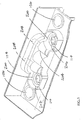
- the connector 200 is used with a battery cover as illustrated in Figures 2 and 3.
- the battery cover 104 includes an opening 107 through which the lead electrode post extends.
- An upstanding wall 110 is formed integrally with the cover 104 and creates a well 109 around the opening 107.
- Terminal pin opening 103 is provided in the recessed portion 106 of the cover 104. It will be readily appreciated that a separate opening 107, upstanding wall 110 and terminal pin opening 103 are provided for each of the positive and negative battery terminals.
- a support 105 may be provided within the well 109 to help hold the connector 200 in place as the connector 200 is installed in the well 109.
- two connectors 200 have been installed in the wells 109 such that the connector apertures 201 are aligned with the battery cover openings 107.
- the connector terminal pins 208 extend through terminal pin openings 103 into the recessed portion 106 of the battery cover 104.
- the terminal assembly is constructed by attaching the battery cover 104 to the casing 102 such that the lead electrode posts (not shown) extend upwardly through each opening 107 in the battery cover 104.
- An O ring (not shown) may be placed around the electrode post and positioned down in the opening 107.
- the O ring may be formed of any suitable material such as an elastomeric material known in the art for this purpose.
- the O ring seals the battery and the battery internals to prevent a potting compound, which is applied around the electrode posts, from leaking down into the battery casing. The seal is also important to prevent an electrolyte mist, which is generated when the battery is charged, from escaping up around the electrode posts.
- a connector 200 is placed in each one of the wells 109 such that the terminal pins 208 extend through terminal pin openings 103.
- the connectors 200 are then soldered directly to the electrode posts.
- a portion of the lead electrode post extending above the base member 202 melts and fills the reservoir 206. This portion has a volume approximately equal to that required to fill the connector reservoir 206 when the portion is melted.
- Additional potting compound may be added to fill each well 109 so as to provide protection for the connectors 200.
- Connector 300 is somewhat similar to connector 200 in that it includes a circular, substantially flat base member 302 having an aperture 301 therein for receiving the electrode post.
- Boss member 304 is formed integrally with, and extends outwardly, generally horizontally from, the base member 302 and further includes an integrally formed terminal pin 308 for connection to an electrical cable.
- This embodiment differs from connector 200 in that it further includes a heat radiator 310 formed integrally with the boss member 304. As was the case with the earlier preferred embodiment, this embodiment is formed from the same type of low resistance, high conductivity materials having a lower resistance and higher conductivity than lead.
- the heat radiator 310 includes a plurality of fins 312 whose purpose is to dissipate the heat generated during battery performance testing. It will be readily appreciated that the heat radiator 310 may take other forms or shapes that are suitable for the heat dissipation function.
- Connector 400 is formed by imbedding a circular, substantially flat base insert 402 in a lead/tin alloy body 409. Insert 402 has an aperture 401 therein for receiving the electrode post.
- a vertical wall 404 is formed integrally with and extends outwardly from the base insert 402 on a horizontal extension of the latter and includes an integrally formed terminal pin 408 for connection to an electrical cable. Although the resulting terminal assembly will have a significant lead content, the lead content will be less than 50%.
- the connector 400 will thus provide a low resistance, high conductivity path therethrough so as to result in lower temperatures being generated during high current flow operation.
Landscapes
- Connection Of Batteries Or Terminals (AREA)
- Secondary Cells (AREA)
Applications Claiming Priority (2)
| Application Number | Priority Date | Filing Date | Title |
|---|---|---|---|
| US09/483,894 US6492060B1 (en) | 2000-01-18 | 2000-01-18 | Low resistance high conductivity battery terminal |
| US483894 | 2000-01-18 |
Publications (2)
| Publication Number | Publication Date |
|---|---|
| EP1119061A2 true EP1119061A2 (de) | 2001-07-25 |
| EP1119061A3 EP1119061A3 (de) | 2003-11-19 |
Family
ID=23921928
Family Applications (1)
| Application Number | Title | Priority Date | Filing Date |
|---|---|---|---|
| EP00307815A Withdrawn EP1119061A3 (de) | 2000-01-18 | 2000-09-11 | Batteriepol mit niedrigem Widerstand und mit hoher Leitfähigkeit |
Country Status (2)
| Country | Link |
|---|---|
| US (1) | US6492060B1 (de) |
| EP (1) | EP1119061A3 (de) |
Cited By (2)
| Publication number | Priority date | Publication date | Assignee | Title |
|---|---|---|---|---|
| US8283820B2 (en) | 2007-01-26 | 2012-10-09 | Vestas Wind Systems A/S | High current connector |
| KR101565041B1 (ko) | 2013-12-31 | 2015-11-02 | 현대자동차주식회사 | 접합형 배터리 포스트 연결단자 및 이를 배터리 포스트에 연결하는 방법 |
Families Citing this family (7)
| Publication number | Priority date | Publication date | Assignee | Title |
|---|---|---|---|---|
| US20040180258A1 (en) * | 2003-03-12 | 2004-09-16 | Sherman Kau | Dual material battery terminal |
| EP2352185A1 (de) * | 2003-10-28 | 2011-08-03 | Johnson Controls Techonology Company | Batterieummantelung mit verbesserter Wärmeverteilung |
| US9831482B2 (en) | 2013-09-06 | 2017-11-28 | Johnson Controls Technology Company | Battery module lid system and method |
| CN107799708A (zh) * | 2017-10-30 | 2018-03-13 | 赵恒祥 | 蓄电池及其端子 |
| BE1026016B1 (de) * | 2018-02-14 | 2019-09-16 | Phoenix Contact Gmbh & Co | Verfahren zum Herstellen eines Kontaktsteckers und Kontaktstecker |
| WO2019173378A1 (en) | 2018-03-05 | 2019-09-12 | Cps Technology Holdings Llc | Cap for battery terminal |
| CN111801813B (zh) | 2018-03-05 | 2023-10-24 | Cps科技控股有限公司 | 电池端子 |
Family Cites Families (25)
| Publication number | Priority date | Publication date | Assignee | Title |
|---|---|---|---|---|
| US3595701A (en) | 1969-08-20 | 1971-07-27 | Keystone Cable Corp | Storage battery connector |
| US4143215A (en) | 1972-10-27 | 1979-03-06 | The Richardson Company | Battery container having cast battery terminal formed therein |
| US3964934A (en) | 1975-05-15 | 1976-06-22 | The Gates Rubber Company | High discharge capability sealed through connector |
| DE2605446A1 (de) | 1975-07-29 | 1977-08-18 | Varta Batterie | Elektrischer akkumulator, insbesondere bleiakkumulator fuer fahrzeuge |
| DE2617016C2 (de) | 1976-04-17 | 1983-09-29 | Varta Batterie Ag, 3000 Hannover | Elektrischer Bleiakkumulator, insbesondere für Fahrzeuge |
| US4207384A (en) | 1978-05-24 | 1980-06-10 | Chloride Group Limited | Electric storage batteries |
| US4191807A (en) | 1978-07-31 | 1980-03-04 | Teledyne Industries, Inc. | Aircraft battery |
| US4237202A (en) | 1978-11-13 | 1980-12-02 | Teledyne Industries, Inc. | Aircraft battery |
| US4239841A (en) | 1979-12-10 | 1980-12-16 | Teledyne Industries, Inc. | Aircraft battery |
| US4478919A (en) | 1981-11-10 | 1984-10-23 | Tiegel Manufacturing Company | Side terminal lead alloy product and process |
| US4472486A (en) | 1983-05-06 | 1984-09-18 | Concorde Battery Corporation | Terminal support member |
| US4482618A (en) | 1983-05-09 | 1984-11-13 | Concorde Battery Corporation | Aircraft battery |
| US4645725A (en) * | 1985-08-30 | 1987-02-24 | Gnb Incorporated | Battery comprising dual terminal bushings |
| DE3610951A1 (de) | 1986-04-02 | 1987-10-08 | Hagen Batterie Ag | Negative elektrode fuer bleiakkumulatoren |
| US4762978A (en) | 1986-07-22 | 1988-08-09 | Tanis Peter G | Aircraft battery assembly |
| JPH01124954A (ja) | 1987-11-09 | 1989-05-17 | Yuasa Battery Co Ltd | 鉛蓄電池 |
| FR2678433A1 (fr) * | 1991-06-28 | 1992-12-31 | Sorapec | Batterie d'accumulateurs monobloc. |
| JP2594027Y2 (ja) | 1992-06-17 | 1999-04-19 | 住友電装株式会社 | バッテリー・ターミナル |
| US5326655A (en) | 1993-05-07 | 1994-07-05 | General Motors Corporation | Battery terminal |
| US5422202A (en) | 1993-06-17 | 1995-06-06 | Tulip Corporation | Side wall electrical battery terminal |
| CA2118866A1 (en) | 1993-06-21 | 1994-12-22 | Clarence A. Meadows | Bipolar battery housing and method |
| US5403678A (en) | 1993-11-16 | 1995-04-04 | Fields; Kevin B. | Corrosion-resistant and protective terminal structure for a battery post |
| US5599641A (en) | 1994-04-20 | 1997-02-04 | Gylling Optima Batteries Ab | Battery terminal and case structure |
| US5626984A (en) | 1995-11-16 | 1997-05-06 | Albini; Salvatore | Battery terminal system |
| US6001506A (en) | 1997-07-30 | 1999-12-14 | Concorde Battery Corporation | Terminal post assembly for lead acid batteries |
-
2000
- 2000-01-18 US US09/483,894 patent/US6492060B1/en not_active Expired - Lifetime
- 2000-09-11 EP EP00307815A patent/EP1119061A3/de not_active Withdrawn
Cited By (2)
| Publication number | Priority date | Publication date | Assignee | Title |
|---|---|---|---|---|
| US8283820B2 (en) | 2007-01-26 | 2012-10-09 | Vestas Wind Systems A/S | High current connector |
| KR101565041B1 (ko) | 2013-12-31 | 2015-11-02 | 현대자동차주식회사 | 접합형 배터리 포스트 연결단자 및 이를 배터리 포스트에 연결하는 방법 |
Also Published As
| Publication number | Publication date |
|---|---|
| EP1119061A3 (de) | 2003-11-19 |
| US6492060B1 (en) | 2002-12-10 |
Similar Documents
| Publication | Publication Date | Title |
|---|---|---|
| RU2316849C1 (ru) | Отливка рсм-модуля и содержащая ее батарея | |
| KR102340419B1 (ko) | 모듈 버스바를 포함하는 배터리 모듈 | |
| JP5254246B2 (ja) | 生産性及び構造的安定性が優れたバッテリーパック | |
| JP6524051B2 (ja) | 導体の接続構造および導電モジュール | |
| US6001506A (en) | Terminal post assembly for lead acid batteries | |
| US7550227B2 (en) | Secondary battery | |
| KR100898691B1 (ko) | 이차전지 | |
| JP5450634B2 (ja) | 新規な構造を有する二次電池パック | |
| JP5374555B2 (ja) | 二次電池 | |
| EP3582291B1 (de) | Batteriemodul | |
| RU2006133325A (ru) | Компоновочный блок колпачка унифицированного типа, содержащий плату защитной схемы, и вторичный аккумулятор, содержащий его | |
| EP2498322B1 (de) | Sekundärbatterie | |
| CN1194061A (zh) | 电池组连接器 | |
| CN214477640U (zh) | 一种电池包高压配电盒bdu | |
| US6492060B1 (en) | Low resistance high conductivity battery terminal | |
| TW201342691A (zh) | 新穎結構的頂蓋總成 | |
| KR102757238B1 (ko) | 터미널 버스 바 | |
| CN110061695A (zh) | 太阳能电池接线盒的模块 | |
| JPH05504225A (ja) | 二重バッテリ | |
| JP2024068735A (ja) | コネクタ | |
| JP3630364B2 (ja) | ヒューズ構造体 | |
| EP1919010B1 (de) | Akku | |
| KR100601502B1 (ko) | 팩 전지 | |
| CN102136402A (zh) | 热敏元件及封装电池 | |
| CN100438128C (zh) | 用于二次电池的组合件壳及方法 |
Legal Events
| Date | Code | Title | Description |
|---|---|---|---|
| PUAI | Public reference made under article 153(3) epc to a published international application that has entered the european phase |
Free format text: ORIGINAL CODE: 0009012 |
|
| AK | Designated contracting states |
Kind code of ref document: A2 Designated state(s): AT BE CH CY DE DK ES FI FR GB GR IE IT LI LU MC NL PT SE |
|
| AX | Request for extension of the european patent |
Free format text: AL;LT;LV;MK;RO;SI |
|
| PUAL | Search report despatched |
Free format text: ORIGINAL CODE: 0009013 |
|
| STAA | Information on the status of an ep patent application or granted ep patent |
Free format text: STATUS: THE APPLICATION IS DEEMED TO BE WITHDRAWN |
|
| AK | Designated contracting states |
Kind code of ref document: A3 Designated state(s): AT BE CH CY DE DK ES FI FR GB GR IE IT LI LU MC NL PT SE |
|
| AX | Request for extension of the european patent |
Extension state: AL LT LV MK RO SI |
|
| RIC1 | Information provided on ipc code assigned before grant |
Ipc: 7H 01M 2/22 B Ipc: 7H 01M 2/06 B Ipc: 7H 01M 2/30 A |
|
| 18D | Application deemed to be withdrawn |
Effective date: 20030401 |