EP1119502B2 - Zigarettenpackung - Google Patents
Zigarettenpackung Download PDFInfo
- Publication number
- EP1119502B2 EP1119502B2 EP99947366A EP99947366A EP1119502B2 EP 1119502 B2 EP1119502 B2 EP 1119502B2 EP 99947366 A EP99947366 A EP 99947366A EP 99947366 A EP99947366 A EP 99947366A EP 1119502 B2 EP1119502 B2 EP 1119502B2
- Authority
- EP
- European Patent Office
- Prior art keywords
- layer
- folding
- region
- blank
- thermal sealing
- Prior art date
- Legal status (The legal status is an assumption and is not a legal conclusion. Google has not performed a legal analysis and makes no representation as to the accuracy of the status listed.)
- Expired - Lifetime
Links
Images


Classifications
-
- B—PERFORMING OPERATIONS; TRANSPORTING
- B65—CONVEYING; PACKING; STORING; HANDLING THIN OR FILAMENTARY MATERIAL
- B65D—CONTAINERS FOR STORAGE OR TRANSPORT OF ARTICLES OR MATERIALS, e.g. BAGS, BARRELS, BOTTLES, BOXES, CANS, CARTONS, CRATES, DRUMS, JARS, TANKS, HOPPERS, FORWARDING CONTAINERS; ACCESSORIES, CLOSURES, OR FITTINGS THEREFOR; PACKAGING ELEMENTS; PACKAGES
- B65D85/00—Containers, packaging elements or packages, specially adapted for particular articles or materials
- B65D85/07—Containers, packaging elements or packages, specially adapted for particular articles or materials for compressible or flexible articles
- B65D85/08—Containers, packaging elements or packages, specially adapted for particular articles or materials for compressible or flexible articles rod-shaped or tubular
- B65D85/10—Containers, packaging elements or packages, specially adapted for particular articles or materials for compressible or flexible articles rod-shaped or tubular for cigarettes
- B65D85/1018—Container formed by a flexible material, i.e. soft-packages
Definitions
- the invention relates to a cigarette pack, in particular soft pack cigarette, with at least one surrounding a group of cigarettes blank of multilayer packaging material, namely with a paper layer as the inside of the pack and with a thermally sealable plastic layer, wherein folding flaps are joined together by thermal sealing.
- Such a cigarette pack is known from GB 1,128,155 A1.
- the blank is multi-layered, namely with an inner paper layer and an aluminum layer facing the outside of the package.
- On the outside of the aluminum layer may be provided a coating of a thermally sealable material.
- the blank is wrapped around a cigarette block in a hose-like manner and overlapping kannlaps are bonded together by gluing or thermal sealing.
- the folding flaps are folded in such a way that in each case the outside aluminum foil or the thermally sealable coating of the folding flaps to be joined are in contact with each other. For this purpose, an additional folding of one of the two folding flaps is to be made.
- Another cigarette soft pack is known from US 4,351,433.
- the packaging material shown there is on the outside and inside, so on the side facing the cigarettes, provided with a coating of a thermally sealable plastic (polyethylene).
- polyethylene thermally sealable plastic
- the invention has for its object to further develop a cigarette pack of the type mentioned, in particular such that the cigarette pack can be produced in a simple manner, while having sufficient stability.
- a cigarette packet according to the invention has the features of claim 1.
- the cigarette pack has a non-sealable material on the side facing the cigarette block. In this way, it can not come to a gluing of the blank with individual cigarettes of the cigarette block when sealing the folding flaps. Furthermore, no additional Palt suitse in the side wall area are required. This simplifies the manufacture of the cigarette pack.
- This simple, two- or three-layer packaging material according to the invention is of particular importance in connection with the design of the cigarette soft pack, in particular in the embodiment of US Pat. No. 5,762,186.
- the Z-shaped fold present in this pack form is lightweight and durable with the packaging material according to the invention can be produced, namely the fact that two legs of the Z-fold are connected to each other throughout, over the entire surface or at least in some areas by thermal sealing.
- the seal of the Z-fold can be applied in the area of a continuous material web.
- the bottom portion of the package according to US Pat. No. 5,762,186 with double-layered folding tabs is designed so that the thermally sealable outer layers of the packaging material lie against one another, so that a particularly dense, durable seal in the bottom wall can be achieved.
- Another special feature of the cigarette pack consists in the design and arrangement of an opening aid for (soft cup) packs of other packaging material.
- An opening tab is defined in the region of an end wall by means of perforation or other weakening lines in the (inner) blank. The perforation line is not visible before opening the package.
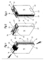
- Such a pack consists of a single blank 10 of packaging material. This surrounds a cigarette group 11.
- the blank forms a front wall 12, an opposite rear wall 13, two narrow, upright side walls 14, 15, a bottom wall 16 and an end wall 17.
- the blank 10 is formed from special packaging material, namely with a multi-layered construction.
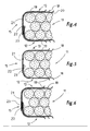
- the main layer or carrier layer is a paper layer 18. This is laminated at least on the outside with a plastic layer 19. This consists of a thermally sealable material, preferably made of polyethylene or polypropylene.
- a further layer may be attached by laminating, so an inner layer 20.
- This may be made of plastic, but of a material having a melting point above the sealing temperature.
- the inner layer 20 may be made of metal, e.g. Aluminum.
- An inner layer consisting of metal can be applied to the paper layer 18 by lamination or vapor deposition.
- FIG. 5 shows an advantageous simple embodiment of the packaging material one with a paper layer 18 as an inner layer and an outer plastic layer 19.
- Fig. 6 again shows a three-layer structure.
- the inner layer 20 is also made of plastic.
- the paper layer 18 is significantly thicker than the other layers, for example 60 g / m 2 (FIGS. 4 and 6) or 70 g / m 2 in a two-layered version (FIG. 5).
- the outer plastic layer 19 has a thickness of 15 gr / m 2 to 30 gr / m 2 .
- the layer construction of the blank 10 matches the illustrated configuration of the package.
- the one-piece blank 10 surrounds the cigarette group 11 such that in the region of a side wall 15 edge strips 21, 22 partially overlap each other. These edge strips 21, 22 are connected to form the side wall 15 by sealing each other.
- the outer edge strip 21 is connected to the outside, so the plastic layer 19 of the inner edge strip 22 by heat and pressure.
- an inner layer 20 made of plastic or metal or the paper layer 18 is connected to the outer plastic layer 19 of the edge strip 22. This results in a over the full length of the blank 11 continuous sealing strip 23 approximately in the width of the overlap (hatched in Fig. 1 and 2).
- the end wall 17 and analogous to the bottom wall 16 consist of mutually partially overlapping Folding tabs.
- Trapezoidal longitudinal tabs 24, 25 are each connected to rear wall 13 and front wall 14 in the region of the end wall.
- On the side walls 14, 15 close in the region of the end wall 17 side tabs 26, 27 at. These lie on the inside, that is partially below the longitudinal tabs 24, 25.
- the side tabs 26, 27 are connected by triangular folding gussets 28, 29 with the longitudinal tabs 24, 25.
- the Faltzwickel 28, 29 are below the longitudinal tabs 24, 25th
- the folding tabs of the end wall 17 are connected to each other by thermal sealing.
- the inside of the outer longitudinal tab 24 is connected to the sealable outer side, namely the plastic layer 19, of the inner longitudinal tab 25.
- the side tabs 26, 27 and the folding gussets 28, 29, the latter are connected by thermal sealing with triangular areas of the side tabs 26, 27.
- the outer plastic layers 19, 20 of the folding tabs 26, 27 on the one hand and the folding tabs 28, 29 on the other hand to each other, so that a particularly strong seal is given.
- the end wall 14 is sufficiently closed or almost aroma-tight.
- the bottom wall 16 may be formed analogously. In the present case, however, a special feature is given.
- Bottom longitudinal tabs 30, 31, bottom side tabs 32, 33 and bottom folding gussets 34, 35 are double-layered or double-walled.
- the blank 10 is provided on the bottom side with a folding strip 36. This is folded along a fold edge 37 to form a double-layered strip. The folding is performed so that partial strips 38, 39 with the inner sides, ie either with the paper layer 18 or the inner layer 20 of another material, abut one another.
- the folding flaps 30..35 are sealable on both sides due to the two-layer design, so that in the hatched areas of the bottom wall 16 (FIG. 3), respective sealable surfaces, namely plastic layers 19, abut one another.
- the bottom wall 16 is particularly stable and durable in this embodiment.
- the folding strip 36 is designed or dimensioned such that a continuous edge strip 52 is formed. This extends in the finished package above the bottom wall 16 inside around as circumferential reinforcing strip, as shown in US 5,762,186.
- a (control) band 40 extending transversely across the end wall 17 is provided.
- the existing paper band 40 is connected here by thermal sealing both front wall 12 and rear wall 13 and with the end wall 17.
- the plastic layer 19 is in each case turned outwards, so that the band 40 can be sealed over its entire surface corresponding to the hatching in FIG. 1.
- a circumferential double fold is formed, namely a Z-fold 41.
- This consists of a strip of material 42 of the blank 10 with two legs 43 , 44 of the Z-fold 41.
- the Z-fold 41 is formed such that a lower fold edge 45 within the blank forms the (apparent) upper edge of the front wall 12, rear wall 13, etc. ( Figure 7).
- a lower folding edge 46 is not visible due to the inner Z-fold 41 outside.
- An upper folding edge 47 forms the transition into the end wall 17.
- the Z-fold 41 is formed so that the two legs 43 and 44 with their (outer) plastic layers 19 abut each other.
- a seal along the Z-folded material strip 42 causes a continuous connection of the legs 43, 44 with each other.
- the opening aid namely a detachable opening tab 48
- the opening aid is created in that areas of folding tabs to be joined together by sealing are not connected to each other by sealing due to appropriate design. As a result, an external folding tab can be grasped by hand and used to separate the opening tab 48.
- a side region of the outer longitudinal tab 24 lying next to the band 40 is not connected to the facing (upper) side of the lower longitudinal tab 25.
- a protective layer 49 is attached to the blank 10, at the top of the (inner) longitudinal tab 25, next to the band 40.
- the protective layer 49 (protective lacquer) is arranged and designed so that a free edge region of the longitudinal tab 24 adjacent to Banderole 40 detected and a triangular grip portion 50 (Fig. 8) of the opening tab 48 can be separated from the longitudinal tab 24.
- the opening tab 48 is defined by a U-shaped weakening line 51 in the blank 10. According to FIG. 9, the weakening line 51 extends from the free edge of the blank in the region of the two longitudinal tabs 24, 25 to the folded edge 47 or slightly beyond it.
- the opening tab 48 thus comprises parts of the longitudinal tabs 24, 25, the side tabs 26 and the Faltzwickel 28, 29.
- an end-side region of the end wall 17 is completely separated next to the banderole 40, so that an approximately rectangular opening is formed.
- the weakening line 51 may be formed as a perforation line. In the present case, however, a weakening line 51 is formed with the aid of a corresponding mechanical separating member or by a laser device, which only extends over part of the cross section of the packaging material, namely on the inside only in the area of the paper layer 18 and, if present, in the region of the inner layer 20 ( Figures 10 and 11). The outer layer or the plastic layer 19 is maintained throughout, but is severed due to the small thickness in the separation of the opening tab 48.
- the blanks according to FIG. 9 are produced from a continuous material web, in which the folding strips 36 and material strips 42 extend in the longitudinal direction of the material web.
- the blank can be printed on the outside, namely in the area of the outer plastic layer, in the usual way.
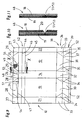
- FIGS. 12, 13 and 14 show details of a (cigarette) package with a modified version of an opening aid, namely an opening tab 48 in the region of the end wall 17.
- the blank 10 used for this embodiment may be in the manner described be formed, but alternatively also without sealable coating, so for example from (coated) paper or the like exist (such an embodiment is not the subject of the claimed invention).
- the two mutually overlapping transverse limbs 54 for separating part of the longitudinal tabs 24, 25 are also in the hidden position, namely underneath the band 40 (FIG. 14).
- a triangular or trapezoidal grip portion 50 of the outer longitudinal tab 24 is detected and separated by lifting, along the outer transverse leg 54. Further actuation of the handle portion 50, the entire opening tab 48 along the (hidden) weakening line 51 separated.
- the handle part 50 of the longitudinal tab 24 to be detected is provided with a marking.
- this is an imprinted arrow 55, which at the same time indicates the actuation direction.
- an outwardly visible mark can be attached by indentation or by slot in the handle portion 50.
- the opening aid according to FIGS. 12 to 14 can also be used in an analogous manner for cigarette packages of the type soft cup in a conventional design, the longitudinal leg of the weakening line 53 being located below an upper edge of the soft cup (consisting of a separate blank).
- the band 40 is fixed in this embodiment by gluing to the package, in the region of a transverse web 56 of the band 40 by two glue points 57, which are arranged outside the range of the weakening line 51.
Landscapes
- Engineering & Computer Science (AREA)
- Mechanical Engineering (AREA)
- Packaging Of Annular Or Rod-Shaped Articles, Wearing Apparel, Cassettes, Or The Like (AREA)
- Packages (AREA)
- Cartons (AREA)
- Laminated Bodies (AREA)
Description
- Die Erfindung betrifft eine Zigarettenpackung, insbesondere Zigaretten-Weichpackung, mit mindestens einem eine Zigarettengruppe umgebenden Zuschnitt aus mehrschichtigem Verpackungsmaterial, nämlich mit einer Papierschicht als Innenseite der Packung und mit einer thermisch siegelbaren Kunststoffschicht, wobei Faltlappen durch thermisches Siegeln miteinander verbunden sind.
- Eine derartige Zigarettenpackung ist aus der GB 1,128,155 A1 bekannt. Der Zuschnitt ist mehrschichtig ausgebildet, nämlich mit einer inneren Papierschicht und einer zur Außenseite der Packung weisenden Aluminiumschicht. An der Außenseite der Aluminiumschicht kann eine Beschichtung aus einem thermisch siegelbaren Material vorgesehen sein. Der Zuschnitt wird schlauchartig um einen Zigarettenblock herumgewickelt und überstehende Faitlappen durch Verleimung oder thermisches Siegeln miteinander verbunden. Im Bereich von Seitenflächen der Packung werden die Faltlappen dabei derart gefaltet, dass jeweils die außenseitige Aluminiumfolie oder die thermisch siegelbare Beschichtung der zu verbindenden Faltlappen Anlage aneinander erhalten. Hierzu ist eine zusätzliche Faltung eines der beiden Faltlappen vorzunehmen.
- Eine weitere Zigaretten-Weichpackung ist aus der US 4,351,433 bekannt. Das dort gezeigte Verpackungsmaterial ist außenseitig und innenseitig, also auf der den Zigaretten unmittelbar zugekehrten Seite, mit einer Beschichtung aus einem thermisch siegelbaren Kunststoff versehen (Polyethylen). Dies hat zur Folge, dass bei der Zufuhr von Wärme die innenliegenden Polyethylenschicht plastifiziert und mit den Zigaretten in Berührung kommt.
- Der Erfindung liegt die Aufgabe zugrunde, eine Zigarettenpackung der eingangs genannten Art weiterzuentwickeln, insbesondere derart, dass die Zigarettenpackung auf einfache Weise herstellbar ist und dabei eine ausreichenden Stabilität aufweist.
- Zur Lösung dieser Aufgabe weist eine erfindungsgemäße Zigarettenpackung die Merkmale des Anspruchs 1 auf.
- Die Zigarettenpackung weist auf der zum Zigarettenblock weisenden Seite ein nicht siegelbares Material auf. Auf diese Weise kann es beim Siegeln der Faltlappen nicht zu einem Verkleben des Zuschnitts mit einzelnen Zigaretten des Zigarettenblocks kommen. Weiterhin sind keine zusätzlichen Paltschritte im Bereich der Seitenwand erforderlich. Hierdurch wird die Herstellung der Zigarettenpackung vereinfacht.
- Eine weitere Zigarettenpackung zur Lösung der vorstehend genannten Aufgabe ist gekennzeichnet durch folgende Merkmale:
- a) die Papierschicht ist außenseitig mit der thermisch siegelbaren Kunststoffschicht versehen, die die Außenseite der Packung bildet,
- b) die Papierschicht ist auf der zur Zigarettengruppe weisenden Seite mit einer weiteren Schicht versehen, nämlich mit einer Innenschicht aus Metall oder Kunststoff mit einem oberhalb der Siegeltemperatur liegenden Schmelzpunkt,
- c) Faltlappen im Bereich einer Stirnwand und einer Bodenwand sind durch thermisches Siegeln miteinander verbunden, wobei die äußere Kunststoffschicht der Faltlappen mit der äußeren Kunststoffschicht oder mit der Innenschicht eines anderen Faltlappens durch thermisches Siegeln verbunden ist,
- d) Faltlappen im Bereich einer Seitenwand sind durch thermisches Siegeln miteinander verbunden, wobei die äußere Kunststoffschicht der Faltlappen mit der der Innenschicht eines anderen Faltlappens durch thermisches Siegeln verbunden ist.
- Diese Lösung weist die gleichen Vorteile wie die vorstehend genannte Zigarettenpackung auf.
- Dieses einfache, zwei- oder dreilagige Verpackungsmaterial ist erfindungsgemäß von besonderer Bedeutung in Verbindung mit der Gestaltung der Zigaretten-Weichpackung, insbesondere in der Ausführung der US 5 762 186. Die bei dieser Packungsform vorhandene Z-förmige Faltung ist mit dem erfindungsgemäßen Verpackungsmaterial leicht und dauerhaft herstellbar, nämlich dadurch, daß zwei Schenkel der Z-Faltung durchgehend, vollflächig oder mindestens in Teilbereichen durch thermisches Siegeln miteinander verbunden sind. Die Siegelung der Z-Faltung kann im Bereich einer fortlaufenden Materialbahn angebracht werden.
- Weiterhin ist der Bodenbereich der Packung entsprechend US 5 762 186 mit doppellagigen Faltlappen so ausgebildet, daß die thermisch siegelbaren Außenschichten des Verpackungsmaterials aneinanderliegen, so daß eine besonders dichte, haltbare Siegelung im Bereich der Bodenwand erzielbar ist.
- Eine weitere Besonderheit der Zigarettenpackung besteht in der Ausgestaltung und Anordnung einer Öffnungshilfe auch für (Weichbecher-)Packungen aus anderem Verpackungsmaterial. Eine Öffnungslasche ist im Bereich einer Stirnwand durch Perforations- oder andere Schwächungslinien im (Innen-)Zuschnitt definiert. Die Perforationslinie ist vor dem Öffnen der Packung nicht frei sichtbar.
- Weitere Merkmale und Einzelheiten der erfindungsgemäßen Zigarettenpackung werden nachfolgend anhand von Ausführungsbeispielen näher erläutert. Es zeigt:
- Fig. 1
- eine Zigarettenpackung des Typs Weichpackung in perspektivischer Ansicht,
- Fig. 2
- die Packung gemäß Fig. 1 ohne (Steuer-)Banderole,
- Fig. 3
- die Packung gemäß Fig. 1 und 2 in einer Bodenseitenansicht,
- Fig. 4
- einen (horizontalen) Teilquerschnitt durch die Packung in vergrößertem Maßstab,
- Fig. 5
- eine Darstellung analog zu Fig. 4 für ein anderes Ausführungsbeispiel,
- Fig. 6
- eine Darstellung analog Fig. 4 und Fig. 5 für ein weiteres Ausführungsbeispiel,
- Fig. 7
- einen stirnseitigen Bereich der Packung in perspektivischer Darstellung,
- Fig. 8
- die Einzelheit der Fig. 7 während des Öffnens der Packung,
- Fig. 9
- einen Zuschnitt für die Fertigung von Packungen gemäß Fig. 1 bis Fig. 8,
- Fig. 10
- einen Schnitt durch den Zuschnitt der Fig. 9 in der Schnittebene X-X der Fig. 9,
- Fig. 11
- einen Schnitt analog zu Fig. 10 für ein anderes Ausführungsbeispiel des Verpackungsmaterials, jeweils stark vergrößert,
- Fig. 12
- einen oberen, stirnseitigen Bereich eines Zuschnitts mit einer gegenüber Fig. 9 veränderten Öffnungshilfe.
- Fig. 13
- den Bereich des Zuschnitts gemäß Fig. 12 nach einem ersten Faltschritt,
- Fig. 14
- einen stirnseitigen Bereich einer Zigarettenpackung des Typs Weichbecher in perspektivischer Darstellung.
- In den Zeichnungen sind Einzelheiten von Weichpackungen für Zigaretten gezeigt, und zwar weitgehend in der Ausführung gemäß US 5 762 186 Eine solche Packung besteht aus einem einzigen Zuschnitt 10 aus Verpackungsmaterial. Dieser umgibt eine Zigarettengruppe 11. Der Zuschnitt bildet eine Vorderwand 12, eine gegenüberliegende Rückwand 13, zwei schmale, aufrechte Seitenwände 14, 15, eine Bodenwand 16 und eine Stirnwand 17.
- Der Zuschnitt 10 wird aus besonderem Verpackungsmaterial gebildet, nämlich mit einem mehrschichtigen Aufbau. Die Hauptschicht bzw. Trägerschicht ist eine Papierschicht 18. Diese ist mindestens auf der Außenseite mit einer Kunststoffschicht 19 kaschiert. Diese besteht aus einem thermisch siegelbaren Material, vorzugsweise aus Polyäthylen oder Polypropylen. Innenseitig, also auf der der Zigarettengruppe 11 zugekehrten Seite, kann eine weitere Schicht durch Kaschieren angebracht sein, also eine Innenschicht 20. Diese kann aus Kunststoff bestehen, jedoch aus einem Material mit einem oberhalb der Siegeltemperatur liegenden Schmelzpunkt. Alternativ kann die Innenschicht 20 aus Metall bestehen, z.B. Aluminium. Eine aus Metall bestehende Innenschicht kann durch Aufkaschieren oder durch Aufdampfen auf die Papierschicht 18 aufgebracht sein.
- Fig. 5 zeigt eine vorteilhafte einfache Ausführung des Verpackungsmaterials einer mit einer Papierschicht 18 als innenliegender Schicht und einer äußeren Kunststoffschicht 19.
- Fig. 6 wiederum zeigt einen dreischichtigen Aufbau. Hier besteht die Innenschicht 20 ebenfalls aus Kunststoff.
- Zweckmäßigerweise ist die Papierschicht 18 deutlich dicker als die übrigen Schichten, z.B. 60 gr/m2 (Fig. 4 und 6) oder 70 gr/m2 bei zweischichtiger Ausführung (Fig. 5). Die äußere Kunststoffschicht 19 hat eine Dicke von 15 gr/m2 bis 30 gr/m2.
- Der Schichtenaufbau des Zuschnitts 10 paßt zu der dargestellten Gestaltung der Packung. Der einstückige Zuschnitt 10 umgibt die Zigarettengruppe 11 derart, daß im Bereich einer Seitenwand 15 Randstreifen 21, 22 einander teilweise überdecken. Diese Randstreifen 21, 22 sind zur Bildung der Seitenwand 15 durch Siegeln miteinander verbunden. Der außenliegende Randstreifen 21 ist mit der Außenseite, also der Kunststoffschicht 19 des innenliegenden Randstreifens 22 durch Wärme und Druck verbunden. Je nach Ausführung des Materials ist eine Innenschicht 20 aus Kunststoff oder Metall oder die Papierschicht 18 mit der äußeren Kunststoffschicht 19 des Randstreifens 22 verbunden. Es entsteht so ein über die volle Länge des Zuschnitts 11 durchgehender Siegelstreifen 23 etwa in der Breite der Überdeckung (schraffiert in Fig. 1 und 2).
- Die Stirnwand 17 und analog die Bodenwand 16 bestehen aus einander teilweise überdeckenden Faltlappen. Im Bereich der Stirnwand sind trapezförmige Längslappen 24, 25 jeweils mit Rückwand 13 und Vorderwand 14 verbunden. An die Seitenwände 14, 15 schließen im Bereich der Stirnwand 17 Seitenlappen 26, 27 an. Diese liegen innenseitig, also teilweise unterhalb der Längslappen 24, 25. Die Seitenlappen 26, 27 sind über dreieckförmige Faltzwickel 28, 29 mit den Längslappen 24, 25 verbunden. Die Faltzwickel 28, 29 liegen unterhalb der Längslappen 24, 25.
- Die Faltlappen der Stirnwand 17 sind durch thermisches Siegeln miteinander verbunden. Im mittleren Bereich der Stirnwand 17 ist die Innenseite des äußeren Längslappens 24 mit der siegelfähigen Außenseite, nämlich der Kunststoffschicht 19, des innenliegenden Längslappens 25 verbunden. Im Bereich der Seitenlappen 26, 27 sowie der Faltzwickel 28, 29 sind letztere durch thermisches Siegeln mit dreieckförmigen Bereichen der Seitenlappen 26, 27 verbunden. In diesem Bereich liegen die äußeren Kunststoffschichten 19, 20 der Faltlappen 26, 27 einerseits und der Faltlappen 28, 29 andererseits aneinander, so daß eine besonders feste Siegelung gegeben ist. Die Stirnwand 14 ist so ausreichend verschlossen bzw. nahezu aromadicht.
- Die Bodenwand 16 kann analog ausgebildet sein. Im vorliegenden Falle ist jedoch eine Besonderheit gegeben. Boden-Längslappen 30, 31, Boden-Seitenlappen 32, 33 und Boden-Faltzwickel 34, 35 sind doppellagig bzw. doppelwandig ausgebildet. Zu diesem Zweck ist der Zuschnitt 10 bodenseitig mit einem Faltstreifen 36 versehen. Dieser wird längs einer Faltkante 37 umgefaltet zur Bildung eines doppellagigen Streifens. Die Faltung wird so vollzogen, daß Teilstreifen 38, 39 mit den Innenseiten, also entweder mit der Papierschicht 18 oder der Innenschicht 20 aus einem anderen Werkstoff, aneinanderliegen. Die Faltlappen 30..35 sind durch die zweilagige Ausbildung an beiden Seiten siegelfähig, so daß in den schraffierten Bereichen der Bodenwand 16 (Fig. 3) jeweils siegelfähige Flächen, nämlich Kunststoffschichten 19, aneinanderliegen. Die Bodenwand 16 ist bei dieser Ausführung besonders stabil und haltbar.
- Der Faltstreifen 36 ist so ausgebildet bzw. bemessen, daß ein durchgehender Randstreifen 52 gebildet ist. Dieser erstreckt sich bei der fertigen Packung oberhalb der Bodenwand 16 innenseitig ringsherum als umlaufender Verstärkungsstreifen, wie in US 5 762 186 gezeigt.
- Bei den vorliegenden Weichpackungen ist im Bereich der Stirnwand 17 eine sich quer über diese hinweg erstreckende (Steuer-)Banderole 40 vorgesehen. Die aus Papier bestehende Banderole 40 ist hier durch thermisches Siegeln sowohl mit Vorderwand 12 und Rückwand 13 als auch mit der Stirnwand 17 verbunden. In diesen Bereichen ist jeweils die Kunststoffschicht 19 nach außen gekehrt, so daß die Banderole 40 vollflächig angesiegelt sein kann entsprechend der Schraffur in Fig. 1.
- Eine weitere Besonderheit liegt darin, daß benachbart zur Stirnwand 17 im Bereich von Vorderwand 12, Rückwand 13. Seitenwänden 14 und 15 eine ringsherumlaufende Doppelfaltung gebildet ist, nämlich eine Z-Faltung 41. Diese besteht aus einem Materialstreifen 42 des Zuschnitts 10 mit zwei Schenkeln 43, 44 der Z-Faltung 41. Die Z-Faltung 41 ist so ausgebildet, daß eine innerhalb des Zuschnitts untere Faltkante 45 die (scheinbare) obere Kante von Vorderwand 12, Rückwand 13 etc. bildet (Fig. 7). Eine untere Faltkante 46 ist aufgrund der innenliegenden Z-Faltung 41 außen nicht erkennbar. Eine obere Faltkante 47 bildet den Übergang in die Stirnwand 17. Die Z-Faltung 41 ist so ausgebildet, daß die beiden Schenkel 43 und 44 mit ihren (äußeren) Kunststoffschichten 19 aneinanderliegen. Eine Siegelung entlang des Z-förmig gefalteten Materialstreifens 42 bewirkt eine durchgehende Verbindung der Schenkel 43, 44 miteinander.
- Eine weitere Besonderheit ist die Ausbildung einer Öffnungshilfe im Bereich der Stirnwand 17. Die Öffnungshilfe, nämlich eine abtrennbare Öffnungslasche 48, wird dadurch geschaffen, daß Bereiche von durch Siegeln miteinander zu verbindende Faltlappen aufgrund entsprechender Ausgestaltung nicht durch Siegeln miteinander verbunden werden. Dadurch kann ein außenliegender Faltlappen von Hand erfaßt und zum Abtrennen der Öffnungslasche 48 verwendet werden.
- Ein neben der Banderole 40 liegender, seitlicher Bereich des äußeren Längslappens 24 ist nicht mit der zugekehrten (oberen) Seite des unteren Längslappens 25 verbunden. Zu diesem Zweck ist eine Schutzschicht 49 am Zuschnitt 10 angebracht, und zwar an der Oberseite des (inneren) Längslappens 25, neben der Banderole 40. Die Schutzschicht 49 (Schutzlack) ist so angeordnet und gestaltet, daß ein freier Randbereich des Längslappens 24 neben der Banderole 40 erfaßt und ein dreieckförmiger Griffteil 50 (Fig. 8) der Öffnungslasche 48 vom Längslappen 24 abgetrennt werden kann.
- Die Öffnungslasche 48 ist durch eine U-förmige Schwächungslinie 51 im Zuschnitt 10 definiert. Gemäß Fig. 9 erstreckt sich die Schwächungslinie 51 vom freien Rand des Zuschnitts im Bereich der beiden Längslappen 24, 25 bis zur Faltkante 47 bzw. geringfügig über diese hinaus. Die Öffnungslasche 48 umfaßt demnach Teile der Längslappen 24, 25, den Seitenlappen 26 und die Faltzwickel 28, 29. Dadurch wird ein endseitiger Bereich der Stirnwand 17 neben der Banderole 40 vollständig abgetrennt, so daß eine annähernd rechteckige Öffnung entsteht.
- Die Schwächungslinie 51 kann als Perforationslinie ausgebildet sein. Im vorliegenden Falle ist jedoch mit Hilfe eines entsprechenden mechanischen Trennorgans oder durch ein Lasergerät eine Schwächungslinie 51 gebildet, die sich nur über einen Teil des Querschnitts des Verpackungsmaterials erstreckt, nämlich innenseitig nur im Bereich der Papierschicht 18 sowie - wenn vorhanden - im Bereich der Innenschicht 20 (Fig. 10 und 11). Die Außenschicht bzw. die Kunststoffschicht 19 bleibt durchgehend erhalten, wird aber aufgrund der geringen Dicke beim Heraustrennen der Öffnungslasche 48 durchtrennt.
- Die Zuschnitte gemäß Fig. 9 werden aus einer fortlaufenden Materialbahn gefertigt, bei der sich die Faltstreifen 36 sowie Materialstreifen 42 in Längsrichtung der Materialbahn erstrecken.
- Der Zuschnitt kann außen, nämlich im Bereich der äußeren Kunststoffschicht, in üblicher Weise bedruckt sein.
- In Fig. 12, Fig. 13 und Fig. 14 sind Einzelheiten einer (Zigaretten-)Packung gezeigt mit einer modifizierten Ausführung einer Öffnungshilfe, nämlich einer Öffnungslasche 48 im Bereich der Stirnwand 17. Der für diese Ausführung eingesetzte Zuschnitt 10 kann in der beschriebenen Weise ausgebildet sein, jedoch alternativ auch ohne siegelfähiger Beschichtung, also beispielsweise aus (beschichtetem) Papier oder dergleichen bestehen (eine solche Ausführung ist nicht Gegenstand der beanspruchten Erfindung).
- Im oberen, der Stirnwand 17 zugekehrten Bereich ist eine in der beschriebenen Weise ausgebildete, ringsherumlaufende Doppelfaltung angebracht, nämlich die Z-Faltung 41. Diese ist von Bedeutung für die Anordnung der Öffnungshilfe bzw. der Öffnungslasche 48. Eine in der Ausgangsstellung (Fig. 12, Fig. 13) U-förmige Schwächungslinie 51 mit einem Längsschenkel 53 und Querschenkeln 54 ist so positioniert, daß vorzugsweise die komplette Schwächungslinie 51 bei der (geschlossenen) Packung unsichtbar, gleichwohl aber wirksam ist. Zu diesem Zweck erstreckt sich der Längsschenkel 53 mit Abstand von der Faltkante 47 derart, daß nach Bildung der Z-Faltung 41 (Fig. 13) der Längsschenkel 53 der Schwächungslinie 51 durch die Z-Faltung 41 verdeckt ist, nämlich unterhalb der Faltkante 45 als oberer, sichtbarer Kante eines (scheinbaren) Bechers liegt (Fig. 13). Bei der fertigen Packung (Fig. 14) liegen die beiden einander überdeckenden Querschenkel 54 zum Abtrennen eines Teils der Längslappen 24, 25 ebenfalls in verdeckter Position, nämlich unterhalb der Banderole 40 (Fig. 14). Zum Öffnen der so ausgebildeten Packung wird, wie üblich, ein dreieck- bzw. trapezförmiger Griffteil 50 des äußeren Längslappens 24 erfaßt und durch Anheben abgetrennt, und zwar entlang dem äußeren Querschenkel 54. Durch weiteres Betätigen des Griffteils 50 wird die gesamte Öffnungslasche 48 entlang der (verdeckten) Schwächungslinie 51 abgetrennt.
- Um das Vorhandensein einer Öffnungshilfe kenntlich zu machen, ist der zu erfassende Griffteil 50 des Längslappens 24 mit einer Markierung versehen. Bei dem Ausführungsbeispiel gemäß Fig. 14 handelt es sich dabei um einen aufgedruckten Pfeil 55, der zugleich die Betätigungsrichtung angibt. Alternativ oder zusätzlich kann benachbart zum Rand der Banderole 40 eine nach außen sichtbare Markierung durch Einkerbung bzw. durch Schlitz im Griffteil 50 angebracht sein.
- Die Öffnungshilfe gemäß Fig. 12 bis Fig. 14 kann in analoger Weise auch für Zigarettenpackungen des Typs Weichbecher in herkömmlicher Ausführung eingesetzt werden, wobei sich der Längsschenkel der Schwächungslinie 53 unterhalb eines oberen Randes des (aus einem gesonderten Zuschnitt bestehenden) Weichbechers befindet.
- Die Banderole 40 ist bei diesem Ausführungsbeispiel durch Klebung an der Packung fixiert, und zwar im Bereich eines Querstegs 56 der Banderole 40 durch zwei Leimpunkte 57, die außerhalb des Bereichs der Schwächungslinie 51 angeordnet sind.
-
- 10
- Zuschnitt
- 11
- Zigarettengruppe
- 12
- Vorderwand
- 13
- Rückwand
- 14
- Seitenwand
- 15
- Seitenwand
- 16
- Bodenwand
- 17
- Stirnwand
- 18
- Papierschicht
- 19
- Kunststoffschicht
- 20
- Innenschicht
- 21
- Randstreifen
- 22
- Randstreifen
- 23
- Siegelstreifen
- 24
- Längslappen
- 25
- Längslappen
- 26
- Seitenlappen
- 27
- Seitenlappen
- 28
- Faltzwickel
- 29
- Faltzwickel
- 30
- Boden-Längslappen
- 31
- Boden-Längslappen
- 32
- Boden-Seitenlappen
- 33
- Boden-Seitenlappen
- 34
- Boden-Faltzwickel
- 35
- Boden-Faltzwickel
- 36
- Faltstreifen
- 37
- Faltkante
- 38
- Teilstreifen
- 39
- Teilstreifen
- 40
- Banderole
- 41
- Z-Faltung
- 42
- Materialstreifen
- 43
- Schenkel
- 44
- Schenkel
- 45
- Faltkante
- 46
- Faltkante
- 47
- Faltkante
- 48
- Öffnungslasche
- 49
- Schutzschicht
- 50
- Griffteil
- 51
- Schwächungslinie
- 52
- Randstreifen
- 53
- Längsschenkel
- 54
- Querschenkel
- 55
- Pfeil
- 56
- Quersteg
- 57
- Leimpunkt
Claims (12)
- Zigarettenpackung, insbesondere Zigaretten-Weichpackung, mit mindestens einem eine Zigarettengruppe (11) umgebenden Zuschnitt (10) aus mehrschichtigem Verpackungsmaterial, nämlich mit einer Papierschicht (18) als Innenseite der Packung und mit einer thermisch siegelbaren Kunststoffschicht (19), wobei Faltlappen durch thermisches Siegeln miteinander verbunden sind, gekennzeichnet durch folgende Merkmale:a) die Papierschicht (18) ist außenseitig mit der thermisch siegelbaren Kunststoffschicht (19) direkt verbunden, die die Außenseite der Packung bildet,b) Faltlappen im Bereich einer Stirnwand (17) und einer Bodenwand (16) sind durch thermisches Siegeln miteinander verbunden, wobei die äußere Kunststoffschicht (19) der Faltlappen mit der äußeren Kunststoffschicht (19) oder mit der inneren Papierschicht (18) eines anderen Faltlappens durch thermisches Siegeln verbunden ist,c) Faltlappen im Bereich einer Seitenwand (15) sind durch thermisches Siegeln miteinander verbunden, wobei die äußere Kunststoffschicht (19) der Faltlappen mit der inneren Papierschicht (18) eines anderen Faltlappens durch thermisches Siegeln verbunden ist,d) im Bereich der Stirnwand (17) sind Flächenbereiche des Zuschnitts (10), nämlich aneinanderliegende Flächenbereiche der Längslappen (24, 25), so ausgebildet, dass eine Verbindung durch thermisches Siegeln nicht stattfindet, nämlich durch Aufbringen einer Schutzschicht (49), nämlich eines Schutzlacks, derart, dass ein Bereich des äußeren Längslappens (24) erfassbar und durch Abtrennen vom Zuschnitt (10) eine Öffnungslasche (48) entsteht.
- Zigarettenpackung, insbesondere Zigaretten-Weichpackung, mit mindestens einem eine Zigarettengruppe (11) umgebenden Zuschnitt (10) aus mehrschichtigem Verpackungsmaterial, nämlich mit einer Papierschicht (18) und mit einer thermisch siegelbaren Kunststoffschicht (19), wobei Faltlappen durch thermisches Siegeln miteinander verbunden sind, gekennzeichnet durch folgende Merkmale:a) die Papierschicht (18) ist außenseitig mit der thermisch siegelbaren Kunststoffschicht (19) direkt verbunden, die die Außenseite der Packung bildet,b) die Papierschicht (18) ist auf der zur Zigarettengruppe (11) weisenden Seite mit einer weiteren Schicht versehen, nämlich mit einer Innenschicht (20) als Innenseite der Packung aus Metall oder Kunststoff mit einem oberhalb der Siegeltemperatur liegenden Schmelzpunkt,c) Faltiappen im Bereich einer Stirnwand (17) und einer Bodenwand (16) sind durch thermisches Siegeln miteinander verbunden, wobei die äußere Kunststoffschicht (19) der Faltlappen mit der äußeren Kunststoffschicht (19) oder mit der Innenschicht (20) eines anderen Faltlappens durch thermisches Siegeln verbunden ist,d) Faltlappen im Bereich einer Seitenwand (15) sind durch thermisches Siegeln miteinander verbunden, wobei die äußere Kunststoffschicht (19) der Faltiappen mit der der Innenschicht (20) eines anderen Faltiappens durch thermisches Siegeln verbunden ist.
- Zigarettenpackung nach Anspruch 1 oder 2, dadurch gekennzeichnet, daß Faltlappen im Bereich der Bodenwand (16) doppelwandig ausgebildet sind, derart, daß die Faltlappen beidseitig die nach außen weisende, thermisch siegelbare Kunststoffschicht (19) aufweisen.
- Zigarettenpackung nach Anspruch 1 oder einem der weiteren Ansprüche, dadurch gekennzeichnet, daß doppellagige Faltungen, insbesondere Z-Faltungen (41) des Zuschnitts (10) so ausgebildet sind, daß Schenkel (43, 44) der Z-Faltung (41) mit den siegelbaren Kunststoffschichten (19) aneinanderliegen und mindestens in Teilbereichen durch thermisches Siegeln miteinander verbunden sind.
- Zigarettenpackung nach Anspruch 2, dadurch gekennzeichnet, daß im Bereich der Stirnwand (17) Flächenbereiche des Zuschnitts (10), insbesondere aneinanderliegende Flächenbereiche der Längslappen (24, 25), so ausgebildet sind, daß eine Verbindung durch thermisches Siegeln nicht stattfindet, insbesondere durch Aufbringen einer Schutzschicht (49), insbesondere einer Schutzlack, derart, daß ein Bereich des äußeren Längslappens (24) erfaßbar und durch Abtrennen vom Zuschnitt (10) eine Öffnungslasche (48) entsteht.
- Zigarettenpackung nach Anspruch 1 oder einem der weiteren Ansprüche, dadurch gekennzeichnet, daß ein Bereich des Zuschnitts (10), insbesondere der Stirnwand (17), durch mindestens eine Schwächungslinie (51) eine abtrennbare Öffnungslasche (48) bildet, vorzugsweise in einem seitlichen Bereich der Stirnwand (17), neben einer sich quer über die Stirnwand (17) erstreckenden Banderole (40).
- Zigarettenpackung nach Anspruch 6, dadurch gekennzeichnet, daß die Schwächungslinie (51) den mehrschichtigen Zuschnitt (10) nicht vollständig durchdringt, insbesondere die äußere Kunststoffschicht (19) geschlossen läßt.
- Zigarettenpackung nach Anspruch 1 oder einem der weiteren Ansprüche, dadurch gekennzeichnet, daß die Papierschicht (18) des mehrschichtigen Zuschnitts (10) einen im Verhältnis zur Kunststoffschicht (19) und gegebenenfalls zur Innenschicht (20) größere Dicke aufweist, insbesondere das drei- bis fünffache Flächengewicht der Kunststoffschicht (19) oder der. Innenschicht (20) .
- Zigarettenpackung nach Anspruch 1 oder einem der weiteren Ansprüche, dadurch gekennzeichnet, daß eine Schwächungslinie (51), insbesondere eine Perforationslinie, zur.Begrenzung einer abziehbaren Öffnungslasche (48) bei geschlossener Packung mindestens teilweise verdeckt ist, insbesondere durch die Banderole (40) und/oder durch die Z-Faltung (41).
- Zigarettenpackung nach Anspruch 9, dadurch gekennzeichnet, daß die Schwächungslinie (51) im Bereich von Vorderwand (12), Rückwand (13) und Seitenwand (14) - der Längsschenkel (53) der Schwächungslinie (51) - mit geringem Abstand unterhalb der (oberen) Faltkante (45) der Z-Faltung (41) und (zwei) Querschenkel (54) der Schwächungslinie (51) einander überdeckend unterhalb eines Querstegs (56) der Banderole (40) positioniert sind.
- Zigarettenpackung nach Anspruch 5 oder 9, dadurch gekennzeichnet, daß ein Griffteil (50) der Öffnungslasche (48) bzw. eines äußeren Längslappens (24) eine Markierung aufweist als Hinweis auf eine Öffnungshilfe, insbesondere einen aufgedruckten Pfeil (55) und/oder eine durch Stanzung gebildete Markierung.
- Zigarettenpackung nach Anspruch 9 oder einem der weiteren Ansprüche, dadurch gekennzeichnet, daß die Banderole (40) mit der Stirnwand (17) und/oder mit Vorderwand (12) und Rückwand (13) durch thermisches Siegeln verbunden ist, wobei vorzugsweise die Banderole (40) innenseitig eine siegelbare Beschichtung aufweist.
Applications Claiming Priority (5)
| Application Number | Priority Date | Filing Date | Title |
|---|---|---|---|
| DE19845894 | 1998-10-06 | ||
| DE19845894 | 1998-10-06 | ||
| DE19915911 | 1999-04-08 | ||
| DE19915911A DE19915911A1 (de) | 1998-10-06 | 1999-04-08 | Zigarettenpackung |
| PCT/EP1999/006856 WO2000020300A1 (de) | 1998-10-06 | 1999-09-16 | Zigarettenpackung |
Publications (3)
| Publication Number | Publication Date |
|---|---|
| EP1119502A1 EP1119502A1 (de) | 2001-08-01 |
| EP1119502B1 EP1119502B1 (de) | 2004-03-17 |
| EP1119502B2 true EP1119502B2 (de) | 2007-06-20 |
Family
ID=26049314
Family Applications (1)
| Application Number | Title | Priority Date | Filing Date |
|---|---|---|---|
| EP99947366A Expired - Lifetime EP1119502B2 (de) | 1998-10-06 | 1999-09-16 | Zigarettenpackung |
Country Status (11)
| Country | Link |
|---|---|
| US (1) | US6595353B1 (de) |
| EP (1) | EP1119502B2 (de) |
| JP (1) | JP2002526348A (de) |
| CN (1) | CN1131828C (de) |
| AT (1) | ATE261881T1 (de) |
| AU (1) | AU6084199A (de) |
| BR (1) | BR9916176B1 (de) |
| ES (1) | ES2216566T5 (de) |
| PL (1) | PL347153A1 (de) |
| TR (1) | TR200100945T2 (de) |
| WO (1) | WO2000020300A1 (de) |
Families Citing this family (13)
| Publication number | Priority date | Publication date | Assignee | Title |
|---|---|---|---|---|
| US8562216B2 (en) * | 2004-04-13 | 2013-10-22 | Pac Worldwide Corporation | Tear away opening for multi-layer plastic pack |
| US8408793B2 (en) | 2006-08-08 | 2013-04-02 | Kellogg Company | Flexible container for pourable product |
| ITBO20070401A1 (it) * | 2007-06-05 | 2007-09-04 | Gd Spa | Stecca di pacchetti di sigarette morbidi con involucro rigido riutilizzabile. |
| JP2009154926A (ja) * | 2007-12-27 | 2009-07-16 | British American Tobacco Pacific Corporation | たばこ産業製品用の包装材料 |
| WO2011007422A1 (ja) * | 2009-07-14 | 2011-01-20 | 日本たばこ産業株式会社 | シガレットパッケージ |
| US20110186062A1 (en) * | 2010-02-01 | 2011-08-04 | Carra Leah Hood | Smoking risk reduction/reduction to quit/cessation aid |
| GB201202565D0 (en) * | 2012-02-15 | 2012-03-28 | British American Tobacco Co | Packaging |
| DE102013012715A1 (de) | 2013-08-01 | 2015-02-05 | Focke & Co. (Gmbh & Co. Kg) | Zigarettenpackung |
| CN106163948B (zh) * | 2014-03-27 | 2019-06-18 | 吉地股份公司 | 用于特别是卷烟的烟草产品的包装 |
| US10384862B2 (en) | 2015-07-24 | 2019-08-20 | R.J. Reynolds Tobacco Company | Moisture barrier coated tobacco product packaging |
| CN108688923B (zh) * | 2017-04-11 | 2022-04-15 | 上海艾尔贝包装科技发展有限公司 | 包装装置及其应用 |
| GB202200806D0 (en) * | 2022-01-21 | 2022-03-09 | British American Tobacco Investments Ltd | A package |
| WO2025157803A1 (en) * | 2024-01-24 | 2025-07-31 | Jt International Sa | Packet for collating a plurality of smoking articles |
Family Cites Families (29)
| Publication number | Priority date | Publication date | Assignee | Title |
|---|---|---|---|---|
| US2026477A (en) * | 1935-02-27 | 1935-12-31 | Blythe Johnson | Commercial package |
| CH271136A (de) * | 1948-01-31 | 1950-10-15 | Reynolds Metals Co | Verpackungsmaterial und Verfahren zu dessen Herstellung. |
| GB710499A (en) | 1951-03-09 | 1954-06-16 | Rose Brothers Ltd | Improvements in label-feeding and applying devices |
| US3265287A (en) * | 1964-11-23 | 1966-08-09 | American Can Co | Iermetically sealed cigarette package with opening feature |
| US3301468A (en) | 1964-12-11 | 1967-01-31 | Philip Morris Inc | Package for tobacco products |
| SE362051B (de) | 1968-03-19 | 1973-11-26 | Akerlund & Rausing Ab | |
| SE361451B (de) | 1971-03-26 | 1973-11-05 | Akerlund & Rausing Ab | |
| US3897900A (en) * | 1973-08-06 | 1975-08-05 | Rexham Corp | Opening arrangement for drumhead cartons |
| DE2417520A1 (de) * | 1974-04-10 | 1975-10-30 | Focke Pfuhl Verpack Automat | Packung aus einem faltbaren zuschnitt, insbesondere zigarettenpackung |
| CH583123A5 (de) | 1974-04-23 | 1976-12-31 | Focke Pfuhl Verpack Automat | |
| DE2613277C2 (de) | 1976-03-29 | 1983-04-07 | Focke & Co, 2810 Verden | Verfahren und Vorrichtung zum Herstellen von quaderförmigen, stabförmige Gegenstände, wie Zigaretten, enthaltende Packungen |
| US4184305A (en) | 1976-04-19 | 1980-01-22 | R. J. Reynolds Tobacco Company | Machine for applying transfers |
| DE2652079C2 (de) | 1976-11-15 | 1983-08-25 | Focke & Pfuhl, 2810 Verden | Packung aus Verbundfolie sowie Verfahren zum Herstellen einer mehrlagigen Verbundfolie |
| DE2743048C2 (de) * | 1977-09-24 | 1987-04-23 | Focke & Pfuhl, 2810 Verden | Packung aus einem mehrlagigen Zuschnitt |
| DE2847161C2 (de) * | 1978-10-30 | 1984-01-12 | Focke & Co, 2810 Verden | Aroma- und feuchtigkeitsdicht verschlossener Inneneinschlag für eine Gruppe von Zigaretten od. dgl. |
| US4351433A (en) * | 1978-12-27 | 1982-09-28 | Molins Plc | Cigarette packets |
| DE2941909A1 (de) * | 1979-10-17 | 1981-04-30 | Wolff Walsrode Ag, 3030 Walsrode | Siegelbare mehrschichtfolie aus polyolefinen |
| DE3124118A1 (de) * | 1981-06-19 | 1983-02-03 | Focke & Co, 2810 Verden | "zigaretten-weichpackung" |
| US4664740A (en) | 1985-06-06 | 1987-05-12 | R. J. Reynolds Tobacco Company | Tax stamping machine |
| BR8604223A (pt) * | 1985-09-04 | 1987-04-28 | Focke & Co | Embalagem em forma de paralelepipedo para cigarros ou semelhantes produtos |
| GB8525040D0 (en) | 1985-10-10 | 1985-11-13 | Molins Plc | Packing machines |
| US4807745A (en) * | 1987-11-27 | 1989-02-28 | R. J. Reynolds Tobacco Company | Barrier sealed packages for cigarettes and other smoking articles |
| EP0430472A3 (en) * | 1989-11-30 | 1992-02-26 | Imperial Chemical Industries Plc | Multiple-layer polyolefin films |
| IE65401B1 (en) * | 1990-04-23 | 1995-10-18 | Reynolds Tobacco Co R | High barrier packages for smoking articles and other products |
| US5542529A (en) * | 1990-04-23 | 1996-08-06 | R. J. Reynolds Tobacco Company | High barrier packages for smoking articles and other products |
| ES2069449T3 (es) * | 1993-07-06 | 1995-05-01 | Tabac Fab Reunies Sa | Embalaje para cigarrillos que incluye mas de un medio de apertura. |
| DE4336378A1 (de) * | 1993-10-25 | 1995-04-27 | Focke & Co | Weichpackung für Zigaretten |
| DE4427862A1 (de) * | 1994-08-05 | 1996-02-08 | Hoechst Ag | Niedrig siegelnde, biaxial orientierte Polyolefin-Mehrschichtfolie, Verfahren zu ihrer Herstellung und ihre Verwendung |
| MY127457A (en) * | 1995-09-28 | 2006-12-29 | Payne P P Ltd | Adhesive tape |
-
1999
- 1999-09-16 US US09/786,989 patent/US6595353B1/en not_active Expired - Fee Related
- 1999-09-16 BR BRPI9916176-1A patent/BR9916176B1/pt not_active IP Right Cessation
- 1999-09-16 AU AU60841/99A patent/AU6084199A/en not_active Abandoned
- 1999-09-16 WO PCT/EP1999/006856 patent/WO2000020300A1/de not_active Ceased
- 1999-09-16 TR TR2001/00945T patent/TR200100945T2/xx unknown
- 1999-09-16 JP JP2000574432A patent/JP2002526348A/ja active Pending
- 1999-09-16 CN CN998118656A patent/CN1131828C/zh not_active Expired - Fee Related
- 1999-09-16 ES ES99947366T patent/ES2216566T5/es not_active Expired - Lifetime
- 1999-09-16 PL PL99347153A patent/PL347153A1/xx not_active IP Right Cessation
- 1999-09-16 EP EP99947366A patent/EP1119502B2/de not_active Expired - Lifetime
- 1999-09-16 AT AT99947366T patent/ATE261881T1/de not_active IP Right Cessation
Also Published As
| Publication number | Publication date |
|---|---|
| CN1131828C (zh) | 2003-12-24 |
| ES2216566T5 (es) | 2007-11-16 |
| ES2216566T3 (es) | 2004-10-16 |
| TR200100945T2 (tr) | 2001-12-21 |
| US6595353B1 (en) | 2003-07-22 |
| EP1119502B1 (de) | 2004-03-17 |
| AU6084199A (en) | 2000-04-26 |
| BR9916176A (pt) | 2001-08-14 |
| EP1119502A1 (de) | 2001-08-01 |
| BR9916176B1 (pt) | 2008-11-18 |
| JP2002526348A (ja) | 2002-08-20 |
| CN1322180A (zh) | 2001-11-14 |
| ATE261881T1 (de) | 2004-04-15 |
| WO2000020300A1 (de) | 2000-04-13 |
| PL347153A1 (en) | 2002-03-25 |
Similar Documents
| Publication | Publication Date | Title |
|---|---|---|
| DE2854443C2 (de) | Packung, insbesondere quaderförmige Packung für Zigaretten, Zigarillos oder dergleichen | |
| EP0401621B1 (de) | Weichpackung, insbesondere Papiertaschentuch-Verpackung | |
| DE2721579C2 (de) | Beutelartiger Behälter zur Aufnahme von Asche und Zigaretten- und Zigarrenresten | |
| DE2833389C2 (de) | Quaderförmige Packung für Zigaretten, Zigarillos o.dgl. | |
| EP0778212B1 (de) | Klappschachtel für Zigaretten oder dergleichen | |
| EP1119502B2 (de) | Zigarettenpackung | |
| WO2011009520A1 (de) | Zigarettenpackung und verfahren zum herstellen von zigarettenpackungen | |
| DE2847161C2 (de) | Aroma- und feuchtigkeitsdicht verschlossener Inneneinschlag für eine Gruppe von Zigaretten od. dgl. | |
| EP1051340B1 (de) | (zigaretten-)packung aus faltbarem verpackungsmaterial | |
| EP2832663B1 (de) | Zigarettenpackung | |
| DE1913600B2 (de) | Zigarettenpackung aus Schichtstoff | |
| EP0055441B1 (de) | Seitenfaltbeutel | |
| DE3329456C2 (de) | Kappenschachtel für Zigaretten oder dergleichen | |
| DE2503421C3 (de) | Quaderförmige Packung für Zigaretten | |
| DE102019132850A1 (de) | Packung für Produkte der Zigarettenindustrie | |
| DE1897846U (de) | Isolierbeutel in form eines blockboden- oder kreuzbodenbeutels. | |
| EP0649797B1 (de) | Weichpackung für Zigaretten | |
| EP0214488A2 (de) | Packung für Zigaretten oder dergleichen | |
| EP1206398B1 (de) | Verfahren zum herstellen von (zigaretten-)packungen | |
| EP0703160B1 (de) | Klappschachtel für Zigaretten oder dergleichen | |
| DE2858166C2 (de) | Quaderförmige Innenumhüllung aus dünnem Verpackungsmaterial (Stanniol-Folie o.dgl.) für Zigaretten o.dgl. | |
| DE19915911A1 (de) | Zigarettenpackung | |
| EP1121297B1 (de) | Packung für zigaretten | |
| DE3927561A1 (de) | Verpackung sowie zuschnitt und verfahren zur herstellung derselben | |
| DE19814255A1 (de) | Packung aus Karton für Zigaretten |
Legal Events
| Date | Code | Title | Description |
|---|---|---|---|
| PUAI | Public reference made under article 153(3) epc to a published international application that has entered the european phase |
Free format text: ORIGINAL CODE: 0009012 |
|
| 17P | Request for examination filed |
Effective date: 20010302 |
|
| AK | Designated contracting states |
Kind code of ref document: A1 Designated state(s): AT BE CH CY DE DK ES FI FR GB GR IE IT LI LU MC NL PT SE |
|
| 17Q | First examination report despatched |
Effective date: 20010910 |
|
| TPAD | Observations filed by third parties |
Free format text: ORIGINAL CODE: EPIDOS TIPA |
|
| GRAP | Despatch of communication of intention to grant a patent |
Free format text: ORIGINAL CODE: EPIDOSNIGR1 |
|
| GRAS | Grant fee paid |
Free format text: ORIGINAL CODE: EPIDOSNIGR3 |
|
| GRAA | (expected) grant |
Free format text: ORIGINAL CODE: 0009210 |
|
| AK | Designated contracting states |
Kind code of ref document: B1 Designated state(s): AT BE CH CY DE DK ES FI FR GB GR IE IT LI LU MC NL PT SE |
|
| PG25 | Lapsed in a contracting state [announced via postgrant information from national office to epo] |
Ref country code: IE Free format text: LAPSE BECAUSE OF FAILURE TO SUBMIT A TRANSLATION OF THE DESCRIPTION OR TO PAY THE FEE WITHIN THE PRESCRIBED TIME-LIMIT Effective date: 20040317 Ref country code: FI Free format text: LAPSE BECAUSE OF FAILURE TO SUBMIT A TRANSLATION OF THE DESCRIPTION OR TO PAY THE FEE WITHIN THE PRESCRIBED TIME-LIMIT Effective date: 20040317 Ref country code: CY Free format text: LAPSE BECAUSE OF FAILURE TO SUBMIT A TRANSLATION OF THE DESCRIPTION OR TO PAY THE FEE WITHIN THE PRESCRIBED TIME-LIMIT Effective date: 20040317 |
|
| REG | Reference to a national code |
Ref country code: GB Ref legal event code: FG4D Free format text: NOT ENGLISH |
|
| REG | Reference to a national code |
Ref country code: CH Ref legal event code: EP |
|
| REG | Reference to a national code |
Ref country code: IE Ref legal event code: FG4D Free format text: GERMAN |
|
| REF | Corresponds to: |
Ref document number: 59908907 Country of ref document: DE Date of ref document: 20040422 Kind code of ref document: P |
|
| REG | Reference to a national code |
Ref country code: CH Ref legal event code: NV Representative=s name: R. A. EGLI & CO. PATENTANWAELTE |
|
| GBT | Gb: translation of ep patent filed (gb section 77(6)(a)/1977) |
Effective date: 20040423 |
|
| PG25 | Lapsed in a contracting state [announced via postgrant information from national office to epo] |
Ref country code: SE Free format text: LAPSE BECAUSE OF FAILURE TO SUBMIT A TRANSLATION OF THE DESCRIPTION OR TO PAY THE FEE WITHIN THE PRESCRIBED TIME-LIMIT Effective date: 20040617 Ref country code: GR Free format text: LAPSE BECAUSE OF FAILURE TO SUBMIT A TRANSLATION OF THE DESCRIPTION OR TO PAY THE FEE WITHIN THE PRESCRIBED TIME-LIMIT Effective date: 20040617 Ref country code: DK Free format text: LAPSE BECAUSE OF FAILURE TO SUBMIT A TRANSLATION OF THE DESCRIPTION OR TO PAY THE FEE WITHIN THE PRESCRIBED TIME-LIMIT Effective date: 20040617 |
|
| PG25 | Lapsed in a contracting state [announced via postgrant information from national office to epo] |
Ref country code: LU Free format text: LAPSE BECAUSE OF NON-PAYMENT OF DUE FEES Effective date: 20040916 Ref country code: AT Free format text: LAPSE BECAUSE OF NON-PAYMENT OF DUE FEES Effective date: 20040916 |
|
| PG25 | Lapsed in a contracting state [announced via postgrant information from national office to epo] |
Ref country code: MC Free format text: LAPSE BECAUSE OF NON-PAYMENT OF DUE FEES Effective date: 20040930 Ref country code: BE Free format text: LAPSE BECAUSE OF NON-PAYMENT OF DUE FEES Effective date: 20040930 |
|
| REG | Reference to a national code |
Ref country code: ES Ref legal event code: FG2A Ref document number: 2216566 Country of ref document: ES Kind code of ref document: T3 |
|
| REG | Reference to a national code |
Ref country code: IE Ref legal event code: FD4D |
|
| RAP2 | Party data changed (patent owner data changed or rights of a patent transferred) |
Owner name: FOCKE & CO. (GMBH & CO. KG) |
|
| PLBQ | Unpublished change to opponent data |
Free format text: ORIGINAL CODE: EPIDOS OPPO |
|
| PLBI | Opposition filed |
Free format text: ORIGINAL CODE: 0009260 |
|
| ET | Fr: translation filed | ||
| NLT2 | Nl: modifications (of names), taken from the european patent patent bulletin |
Owner name: FOCKE & CO. (GMBH & CO. KG) |
|
| PLAX | Notice of opposition and request to file observation + time limit sent |
Free format text: ORIGINAL CODE: EPIDOSNOBS2 |
|
| 26 | Opposition filed |
Opponent name: G.D SOCIETAE PER AZIONI Effective date: 20041203 |
|
| BERE | Be: lapsed |
Owner name: *FOCKE & CO. (G.M.B.H. & CO.) Effective date: 20040930 |
|
| NLR1 | Nl: opposition has been filed with the epo |
Opponent name: G.D SOCIETA PER AZIONI |
|
| PLAX | Notice of opposition and request to file observation + time limit sent |
Free format text: ORIGINAL CODE: EPIDOSNOBS2 |
|
| PLAF | Information modified related to communication of a notice of opposition and request to file observations + time limit |
Free format text: ORIGINAL CODE: EPIDOSCOBS2 |
|
| PLBB | Reply of patent proprietor to notice(s) of opposition received |
Free format text: ORIGINAL CODE: EPIDOSNOBS3 |
|
| PGFP | Annual fee paid to national office [announced via postgrant information from national office to epo] |
Ref country code: NL Payment date: 20050904 Year of fee payment: 7 |
|
| PGFP | Annual fee paid to national office [announced via postgrant information from national office to epo] |
Ref country code: GB Payment date: 20050914 Year of fee payment: 7 |
|
| PG25 | Lapsed in a contracting state [announced via postgrant information from national office to epo] |
Ref country code: NL Free format text: LAPSE BECAUSE OF NON-PAYMENT OF DUE FEES Effective date: 20070401 |
|
| PUAH | Patent maintained in amended form |
Free format text: ORIGINAL CODE: 0009272 |
|
| STAA | Information on the status of an ep patent application or granted ep patent |
Free format text: STATUS: PATENT MAINTAINED AS AMENDED |
|
| GBPC | Gb: european patent ceased through non-payment of renewal fee |
Effective date: 20060916 |
|
| NLV4 | Nl: lapsed or anulled due to non-payment of the annual fee |
Effective date: 20070401 |
|
| 27A | Patent maintained in amended form |
Effective date: 20070620 |
|
| AK | Designated contracting states |
Kind code of ref document: B2 Designated state(s): AT BE CH CY DE DK ES FI FR GB GR IE IT LI LU MC NL PT SE |
|
| REG | Reference to a national code |
Ref country code: CH Ref legal event code: AEN Free format text: AUFRECHTERHALTUNG DES PATENTES IN GEAENDERTER FORM |
|
| REG | Reference to a national code |
Ref country code: ES Ref legal event code: DC2A Date of ref document: 20070626 Kind code of ref document: T5 |
|
| PG25 | Lapsed in a contracting state [announced via postgrant information from national office to epo] |
Ref country code: GB Free format text: LAPSE BECAUSE OF NON-PAYMENT OF DUE FEES Effective date: 20060916 |
|
| ET3 | Fr: translation filed ** decision concerning opposition | ||
| BERE | Be: lapsed |
Owner name: *FOCKE & CO. (G.M.B.H. & CO.) Effective date: 20040930 |
|
| PG25 | Lapsed in a contracting state [announced via postgrant information from national office to epo] |
Ref country code: PT Free format text: LAPSE BECAUSE OF NON-PAYMENT OF DUE FEES Effective date: 20040817 |
|
| PGFP | Annual fee paid to national office [announced via postgrant information from national office to epo] |
Ref country code: CH Payment date: 20091006 Year of fee payment: 11 |
|
| PGFP | Annual fee paid to national office [announced via postgrant information from national office to epo] |
Ref country code: FR Payment date: 20091012 Year of fee payment: 11 |
|
| REG | Reference to a national code |
Ref country code: CH Ref legal event code: PL |
|
| REG | Reference to a national code |
Ref country code: FR Ref legal event code: ST Effective date: 20110531 |
|
| PG25 | Lapsed in a contracting state [announced via postgrant information from national office to epo] |
Ref country code: LI Free format text: LAPSE BECAUSE OF NON-PAYMENT OF DUE FEES Effective date: 20100930 Ref country code: FR Free format text: LAPSE BECAUSE OF NON-PAYMENT OF DUE FEES Effective date: 20100930 Ref country code: CH Free format text: LAPSE BECAUSE OF NON-PAYMENT OF DUE FEES Effective date: 20100930 |
|
| PGFP | Annual fee paid to national office [announced via postgrant information from national office to epo] |
Ref country code: ES Payment date: 20130828 Year of fee payment: 15 |
|
| PGFP | Annual fee paid to national office [announced via postgrant information from national office to epo] |
Ref country code: IT Payment date: 20140912 Year of fee payment: 16 |
|
| PGFP | Annual fee paid to national office [announced via postgrant information from national office to epo] |
Ref country code: DE Payment date: 20140930 Year of fee payment: 16 |
|
| REG | Reference to a national code |
Ref country code: ES Ref legal event code: FD2A Effective date: 20160205 |
|
| REG | Reference to a national code |
Ref country code: DE Ref legal event code: R119 Ref document number: 59908907 Country of ref document: DE |
|
| PG25 | Lapsed in a contracting state [announced via postgrant information from national office to epo] |
Ref country code: ES Free format text: LAPSE BECAUSE OF NON-PAYMENT OF DUE FEES Effective date: 20140917 Ref country code: IT Free format text: LAPSE BECAUSE OF NON-PAYMENT OF DUE FEES Effective date: 20150916 |
|
| PG25 | Lapsed in a contracting state [announced via postgrant information from national office to epo] |
Ref country code: DE Free format text: LAPSE BECAUSE OF NON-PAYMENT OF DUE FEES Effective date: 20160401 |