EP1120032A2 - Construction pour la traite automatique d'animaux - Google Patents
Construction pour la traite automatique d'animaux Download PDFInfo
- Publication number
- EP1120032A2 EP1120032A2 EP01201590A EP01201590A EP1120032A2 EP 1120032 A2 EP1120032 A2 EP 1120032A2 EP 01201590 A EP01201590 A EP 01201590A EP 01201590 A EP01201590 A EP 01201590A EP 1120032 A2 EP1120032 A2 EP 1120032A2
- Authority
- EP
- European Patent Office
- Prior art keywords
- construction
- carrier
- teat cups
- milking
- carriers
- Prior art date
- Legal status (The legal status is an assumption and is not a legal conclusion. Google has not performed a legal analysis and makes no representation as to the accuracy of the status listed.)
- Granted
Links
Images


Classifications
-
- A—HUMAN NECESSITIES
- A01—AGRICULTURE; FORESTRY; ANIMAL HUSBANDRY; HUNTING; TRAPPING; FISHING
- A01J—MANUFACTURE OF DAIRY PRODUCTS
- A01J5/00—Milking machines or devices
- A01J5/017—Automatic attaching or detaching of clusters
- A01J5/0175—Attaching of clusters
Definitions
- the present invention relates to a construction for automatically milking animals, such as cows, comprising a milking robot with teat cups.
- the present invention provides an alternative construction for automatically milking animals, such as cows, comprising a milking robot with teat cups, in which the carriers reach with one end to inside of the milking box, whereas the means for positioning the teat cups to the teats are mainly located at the outside of the milking box.
- the present invention furthermore relates to a construction for automatically milking animals, such as cows, comprising a milking robot with teat cups, characterized in that the teat cups are mounted during the connection of the teat cups to the teats with the upper edges of at least two teat cups directly against each other.
- the present invention further relates to a method for automatically milking animals, such as cows, in a construction comprising a milking box and a milking robot with teat cups, the method being characterized in that the teat cups are moved separately, in pairs or all simultaneously, from a rest position to a working position, whilst the carriers of the teat cups are moved in at least two different directions in an approximately horizontal plane to under the udder of an animal in order to enable connection of the teat cups to the teats of the animal by an upward motion. More specifically, the feature that the teat cups with carrier arms can simultaneously be coupled from different directions to the teats of the animal renders it possible to realize a fast and advantageous coupling of the teat cups.
- the present invention furthermore relates to a construction for automatically milking animals, such as cows, comprising a milking box with a milking robot having at least two robot arm constructions with carriers for teat cups, which carriers are movable in a horizontal plane and in an up- and downward direction.
- the construction is characterized in that, during milking, the carriers of the teat cups are arranged in an approximately horizontal plane in the shape of a star around the udder of an animal.
- At least one carrier is in a position behind the hind leg of an animal and that at least one other carrier is in a position in front of a hind leg of this animal.
- the carriers are preferably of a curved shape.
- the present invention furthermore relates to a construction for automatically milking animals, such as cows, comprising a milking robot with teat cups, characterized in that a plurality of carriers are present for one or more teat cups and of which, during milking, at least one carrier is in a position behind a hind leg of an animal and at least one other carrier in a position in front of a hind leg of this animal.
- a carrier for one or more teat cups may be capable of being moved from both a rest position, preferably outside the milking box, to a working position, said carrier in this working position being movable in a predominantly horizontal plane in two different directions which are preferably perpendicular to each other.
- the adjusting means of the carriers are disposed remotely from the udder of the animal, preferably near the wall of the milking box; such a construction enables an accurate and fast manner of coupling of the teat cups to the teats, whilst, if so desired, two or even all four of the teat cups can be coupled to the teats simultaneously.
- the construction is furthermore characterized in that during milking, using a flexible connecting element, such as a cable or a cord, a teat cup is connected in a freely moveable manner to a relevant carrier and after milking can be pulled against the end of this carrier. If the teat cups are connected capably of free motion to the carriers, no lateral or other forces are exerted on the teats and the animal is in a comfortable position of being milked by the milking robot.
- a flexible connecting element such as a cable or a cord
- the construction, as described in the preamble is characterized in that, at its side, the teat cup is provided with a bulge which can be pulled with the end of a flexible connecting element into a corresponding shaped recess in the end of a carrier. This measure renders it possible to pull the teat cup, which during milking can move freely with respect to the carrier, in a defined position against the carrier after milking.
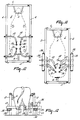
- Figures 1 and 2 show a plan view and a side view, respectively, of a milking box 1 which is formed by a frame 2, which constitutes the two sides of the milking box 1, a door 3, via which an animal to be milked can enter the milking box, and a door 4, through which a milked animal can again leave the milking box.
- the door 3 is equipped with positioning means 6 for retaining an animal present in the milking box in a more or less defined position in the milking box 1.
- the milking box 1 is provided with a milking robot 7 which, in this embodiment, comprises two robot arm constructions 8, which are arranged on either side of the milking box 1.
- These robot arm constructions 8 are shown only schematically and include a vertically arranged pillar 9, to the upper end of which a parallelogram construction 10 is attached, a supporting element 11 being movable in height with the aid of this parallelogram construction 10.
- this supporting element 11 is pivotal about a vertical shaft 12.
- a carrier 13 is arranged in such a manner extending in two directions, which are perpendicular to each other, that it is movable in a horizontal plane.
- the motional means for moving the supporting element 11 in the vertical direction with the aid of the parallelogram construction 10 and the motional means for pivoting same about the vertical shaft 12 are not shown in the drawings, the means with the aid of which the carrier 13 is movable with respect to the supporting element 11 in two directions which extend perpendicularly to each other are however indeed shown.
- Both these latter motional means and the non-shown motional means are preferably constituted by pneumatic cylinders 14 and 15. These cylinders 14 and 15 act as a kind of spring to allow a limited freedom of motion of the carrier 13, more specifically when it comes in some way or another in contact with the animal in a rough manner.
- the carrier 13 extends in two directions.
- FIG. 1 shows that that portion of the carrier 13 that is connected to the supporting element 11 extends in a horizontal plane transversely to the longitudinal direction of the milking box 1, whereas the other end of the carrier 13 extends in a horizontal plane obliquely rearwardly and inwardly.
- the carriers 13 allows an easy access to the teats of the animal without being obstructed by the legs and without the carriers 13 of the teat cups interfering with each other.
- each of the carriers 13 is suitable for carrying two teat cups 16 and 17.
- One of the carriers 13 is equipped with a detection device 18, such as a laser. This detection device 18 is disposed in such a manner that, when the carrier 13 to which this detection device is attached has been moved to under the animal in the position shown in Figure 1, the detection device 18 is located approximately in the midway point under the animal at the leading side of the udder.
- this detection device 18 which is disposed in such a manner that it reciprocates or rotates about a vertical shaft, it is possible to determine the position of the four teats with respect to the carrier 13 to which the detection device 18 is connected.
- the carrier 13, to which the detection device 18 is connected can be moved, until the position of a teat, determined by the detection device 18, with respect to the detection device 18 corresponds to the position of a relevant teat cup on the last-mentioned carrier with respect to the detection device 18.
- the position of the carrier to which the detection device 18 is connected and the position, measured with the aid of the detection device 18, of the relevant teats with respect to the carrier to which the detection device 18 is connected must be taken into account.
- the carriers 13 are at least partly of a tubular design and comprise a non-shown cylinder, whose end is connected to a teat cup 16, 17 via a flexible connecting element 19.
- This flexible connecting element 19, which may be constituted by a cord or a cable, renders it possible for the teat cup connected thereto to remain, during milking, in connection in a freely movable manner with the relevant carrier 13, more specifically by refraining from energizing, during milking, the cylinder to which the flexible connecting element 19 is connected and which is disposed in the tubular carrier 13, whilst, after milking, by energizing the last-mentioned cylinder, the teat cup can be pulled up against the end of the carrier 13.
- this carrier can be moved more in particular in such a manner that the other teat cup connected to this carrier is moved to under another teat for connection to said teat.
- the two robot arm constructions 8 are disposed on both sides of the milking box 1 in the rest condition.
- an animal to be milked can enter the milking box 1; the supporting element 11 has then been pivoted in such a manner about the vertical shaft 12 that this supporting element extends outwardly transversely to the longitudinal direction of the milking box 1.
- the carriers 13 with the teat cups 16 and 17 are then completely outside the milking box 1.
- the detection device 18 is in a position approximately in the midway point under the animal, more specifically at the leading side of the udder of this animal.
- the carriers 13 can now be moved individually or simultaneously in such a manner in two directions which are perpendicular to each other, that the teat cups 16 arrive under the rear teats of the animal, so that only an upward motion of the teat cups 16 is sufficient to connect them to these teats.
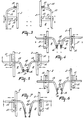
- This situation is shown in Figure 5.
- the relevant cylinders contained in the tubular carriers, of which each cylinder is connected to a teat cup 16 via a flexible connecting element 19, are released, so that the carriers 13 can be advanced without pulling the teat cups 16 from the teats.
- the carriers 13 are now moved such that the teat cups 17 arrive under the leading teats of the animal, whereafter the teat cups 17 can be connected individually or simultaneously by an upward motion to the leading teats of the animal.
- Figure 6 This situation is shown in Figure 6.
- FIGS 8 and 9 show in a plan view and a side view, respectively, how the two teat cups 16 and 17 are connected to the end of a carrier 13.
- each teat cup is provided with a bulging portion, 'preferably a conical bulge 20, to which the flexible connecting element 19 is connected.
- That end of a carrier 13 that is located near the teat cups is provided with a through-connection element 21.
- This through-connection element 21 has at its exterior side two recesses 22, the shape of which corresponds to the conical bulge 20 at the side of the teat cups 16, 17.
- Such a conical recess 22 has a through-bore through the through-connection element 21, through which the relevant flexible connecting element 19 is passed, so that when this flexible connecting element 19 is tightened, the conical bulge 20 at the side of the relevant teat cup is pulled into the relevant conical recess 22 in the through-connection element 21.
- the through-connection element 21 also serves for the through-connection of the milk and/or pulsation tube leading to a teat cup.
- the milk tube 23 and/or the pulsation tube 24 are passed through the tubular carrier 13 to the respective points of connection 25 and 26 provided for that purpose in the through-connection element 21.
- the milk tube 23 and the pulsation tube 24, if present, must be of a flexible construction between the through-connection element 21 and the teat cups 16 and 17.
- the end of the tubular carrier 13 is provided at both the bottom side and the upper side with a slotted aperture 27 and 28, respectively.
- the milk and pulsation tubes extend one above the other, passing underneath the end of the carrier 13 and thereafter are passed upwardly through the carrier 13 through the slotted aperture 27 at the bottom side of the carrier 13 and via the slotted aperture 28 and the upper side of the carrier 13 in a loop shape over and along the carrier 13 forwardly and downwardly to the connecting points 31 and 32 at the rear side of the through-connection element 21; to that end, this rear side is provided with a bevelled plane 33.
- each carries 13, each for a teat cup 34, and 35, 36 and 37, respectively, are shown.
- the carriers are arranged in the shape of a star and also here extend each in two directions.
- one of the carriers 13 is equipped with a detection device 18.
- the carriers 13 are arranged such that the carriers with the teat cups 34, 35 which are to be connected to the leading teats of the animal must approach the udder from the side of the milking box 1 passing between the front and hind legs, whereas the carriers with the teat cups 36, 37 which are intended for connection to the rear teats must be moved to under the animal passing between the two hind legs.
- the carriers 13 are still further remote from each other and can easily be moved to under the animal independently of each other, both individually and simultaneously, without interfering with each other.
- the carriers may again have been disposed such that they are movable in two directions and moreover are arranged pivotally near the exterior wall of the milking box 1.
- a similar construction as shown in Figure 1 is then possible.
- two carriers 13, each carrying one teat cup for a leading and one for a trailing teat, are each time moved to under the udder of the animal from one side of the milking box 1 passing between a front and a hind leg. This construction is shown in a rear view in Figure 12.
- the carriers 13 are pivotal about a horizontal pivot shaft 38 which extends in the lengthwise direction of the milking box 1 and, in the embodiment shown, is disposed just next to the longitudinal side wall of the milking box 1. Also in this case, the carriers 13 are movable in both the lengthwise direction of the milking box 1 and in the direction transversely thereto.
- each of the teat cups 34 - 37 to a carrier 13 is here similar to the manner in which in Figures 8 and 9 two teat cups are coupled to a carrier 13.
- the connection of one teat cup and one carrier is shown in Figures 13 and 14.
- the teat cups is provided at its side with a conical bulging portion 20, to which a flexible connecting element 19 is secured, whilst with the aid of this flexible connecting element the conical bulging portion can be pulled into a recess 22 of a through-connection element 21.
- the recess 22 has a through-bore for the flexible connecting element.
- the carrier 13 is provided at both the bottom side and the upper side with respective slotted apertures 27 and 28, so that a milk and/or pulsation tube 23 and 24, respectively, can be passed at the bottom side of the carrier 13 through the carrier 13 in the upper direction and through the slotted aperture 28 in the upper side of the carrier 13 and be connected in the shape of a loop to the through-connection element 21 in a similar manner as shown in Figure 9.
Landscapes
- Life Sciences & Earth Sciences (AREA)
- Animal Husbandry (AREA)
- Environmental Sciences (AREA)
- External Artificial Organs (AREA)
- Toys (AREA)
- Housing For Livestock And Birds (AREA)
- Feeding And Watering For Cattle Raising And Animal Husbandry (AREA)
- Catching Or Destruction (AREA)
- Orthopedics, Nursing, And Contraception (AREA)
- Manipulator (AREA)
- Investigating Or Analysing Materials By Optical Means (AREA)
- Farming Of Fish And Shellfish (AREA)
Applications Claiming Priority (4)
| Application Number | Priority Date | Filing Date | Title |
|---|---|---|---|
| NL9300578A NL9300578A (nl) | 1993-04-01 | 1993-04-01 | Inrichting voor het automatisch melken van dieren. |
| NL9300578 | 1993-04-01 | ||
| EP94913203A EP0693871B2 (fr) | 1993-04-01 | 1994-03-29 | Installation de traite automatique d'animaux |
| EP97202059A EP0804874B1 (fr) | 1993-04-01 | 1994-03-29 | Construction pour la traite automatique d'animaux |
Related Parent Applications (1)
| Application Number | Title | Priority Date | Filing Date |
|---|---|---|---|
| EP97202059A Division EP0804874B1 (fr) | 1993-04-01 | 1994-03-29 | Construction pour la traite automatique d'animaux |
Publications (3)
| Publication Number | Publication Date |
|---|---|
| EP1120032A2 true EP1120032A2 (fr) | 2001-08-01 |
| EP1120032A3 EP1120032A3 (fr) | 2002-06-12 |
| EP1120032B1 EP1120032B1 (fr) | 2006-08-09 |
Family
ID=19862242
Family Applications (3)
| Application Number | Title | Priority Date | Filing Date |
|---|---|---|---|
| EP01201590A Expired - Lifetime EP1120032B1 (fr) | 1993-04-01 | 1994-03-29 | Construction pour la traite automatique d'animaux |
| EP97202059A Expired - Lifetime EP0804874B1 (fr) | 1993-04-01 | 1994-03-29 | Construction pour la traite automatique d'animaux |
| EP94913203A Expired - Lifetime EP0693871B2 (fr) | 1993-04-01 | 1994-03-29 | Installation de traite automatique d'animaux |
Family Applications After (2)
| Application Number | Title | Priority Date | Filing Date |
|---|---|---|---|
| EP97202059A Expired - Lifetime EP0804874B1 (fr) | 1993-04-01 | 1994-03-29 | Construction pour la traite automatique d'animaux |
| EP94913203A Expired - Lifetime EP0693871B2 (fr) | 1993-04-01 | 1994-03-29 | Installation de traite automatique d'animaux |
Country Status (7)
| Country | Link |
|---|---|
| US (1) | US5713301A (fr) |
| EP (3) | EP1120032B1 (fr) |
| JP (1) | JPH08508401A (fr) |
| AU (1) | AU684502B2 (fr) |
| DE (4) | DE69408308T3 (fr) |
| NL (1) | NL9300578A (fr) |
| WO (1) | WO1994022292A1 (fr) |
Families Citing this family (14)
| Publication number | Priority date | Publication date | Assignee | Title |
|---|---|---|---|---|
| NL9401114A (nl) * | 1994-07-04 | 1996-02-01 | Maasland Nv | Constructie met een inrichting voor het automatisch melken van dieren. |
| SE503492C2 (sv) * | 1994-10-12 | 1996-06-24 | Tetra Laval Holdings & Finance | Mjölkningsanläggning med en första och en andra mjölkningsenhet |
| US6116188A (en) * | 1996-04-24 | 2000-09-12 | Van Der Lely; Cornelis | Method of milking animals |
| SE9701310D0 (sv) * | 1997-04-11 | 1997-04-11 | Alfa Laval Agri Ab | A teatcup magazine, a milking arrangement, and a method of handling a teatcup |
| US5937786A (en) * | 1997-04-17 | 1999-08-17 | Peacock Bros. Inc. | Milking machine retractor |
| NL1006175C2 (nl) * | 1997-05-30 | 1998-12-01 | Maasland Nv | Inrichting voor het melken van dieren. |
| SE9800100D0 (sv) * | 1998-01-16 | 1998-01-16 | Alfa Laval Agri Ab | Förfarande och anordning för mjölkning av ett djur |
| NL1035117C2 (nl) * | 2008-03-04 | 2009-09-07 | Lely Patent Nv | Melkinrichting. |
| EP2241179B1 (fr) * | 2009-04-16 | 2017-05-17 | DeLaval Holding AB | Salle de traite et procédé de fonctionnement |
| WO2012070999A1 (fr) * | 2010-11-23 | 2012-05-31 | Delaval Holding Ab | Salle de traite pour animaux |
| US9215861B2 (en) * | 2011-04-28 | 2015-12-22 | Technologies Holdings Corp. | Milking box with robotic attacher and backplane for tracking movements of a dairy animal |
| US9265227B2 (en) * | 2011-04-28 | 2016-02-23 | Technologies Holdings Corp. | System and method for improved attachment of a cup to a dairy animal |
| US9675041B2 (en) * | 2012-11-21 | 2017-06-13 | Delaval Holding Ab | Leg spreading device to be mounted in a milking stall |
| NL2012747B1 (nl) * | 2014-05-02 | 2016-02-23 | Technologies Holdings Corp | Dubbele grijper voor het aanbrengen van melkbekers bij een te melken dier, spoelbeker daarvoor en melkmachine voorzien daarvan, en werkwijze voor het melken. |
Family Cites Families (19)
| Publication number | Priority date | Publication date | Assignee | Title |
|---|---|---|---|---|
| US3603292A (en) * | 1969-07-17 | 1971-09-07 | Alfa Laval Ab | Automated stall and milking equipment |
| US3726252A (en) * | 1971-01-11 | 1973-04-10 | Babson Bros Co | Automatic milker |
| EP0320496B2 (fr) * | 1985-01-16 | 1999-09-15 | Maasland N.V. | Dispositif de traíte automatique d'animaux |
| SU1311642A1 (ru) † | 1985-08-08 | 1987-05-23 | Всероссийский научно-исследовательский и проектно-технологический институт механизации и электрификации сельского хозяйства | Доильный аппарат |
| NL8502434A (nl) * | 1985-09-04 | 1987-04-01 | Multinorm Bv | Melkinrichting. |
| NL8600076A (nl) * | 1986-01-16 | 1987-08-17 | Lely Nv C Van Der | Werkwijze en inrichting voor het melken van een dier. |
| EP0306579B1 (fr) * | 1987-09-08 | 1992-01-02 | Centre National Du Machinisme Agricole, Du Genie Rural, Des Eaux Et Des Forets (Cemagref) | Installation de traite automatique |
| NL193648C (nl) * | 1986-08-27 | 2000-06-06 | Lely Nv C Van Der | Inrichting voor het melken van dieren. |
| NL193715C (nl) * | 1987-07-23 | 2000-08-04 | Lely Nv C Van Der | Inrichting voor het melken van een dier. |
| NL8701848A (nl) * | 1987-08-05 | 1989-03-01 | Gascoigne Melotte Bv | Melkinrichting. |
| NL8702285A (nl) * | 1987-09-24 | 1989-04-17 | Gascoigne Melotte Bv | Melkinrichting. |
| EP0619941A3 (fr) * | 1988-01-08 | 1994-12-14 | Prolion Bv | Elément à positionner un animal. |
| NL8802332A (nl) * | 1988-09-21 | 1990-04-17 | Lely Nv C Van Der | Inrichting voor het melken van een dier. |
| GB8900084D0 (en) * | 1989-01-04 | 1989-03-01 | British Res Agricult Eng | Milking |
| NL193553C (nl) * | 1989-02-27 | 2003-01-10 | Lely Entpr Ag | Melkinstallatie. |
| DE4113700A1 (de) † | 1991-04-26 | 1992-10-29 | Dieter Dipl Ing Schillingmann | Verfahren zum automatischen melken von in melkboxen stehenden milchkuehen, sowie melkbox, roboter und melkmodul zur durchfuehrung dieses verfahrens |
| NL9101064A (nl) * | 1991-06-20 | 1993-01-18 | Gascoigne Melotte Bv | Inrichting voor het aanleggen respectievelijk verwijderen van een stel speenbekers bij dieren. |
| GB9113405D0 (en) * | 1991-06-20 | 1991-08-07 | Silsoe Research Inst | Automatic milking |
| DE19924439A1 (de) † | 1999-05-28 | 2000-11-30 | Bayer Ag | Schnell vernetzendes Fluorpolymer |
-
1993
- 1993-04-01 NL NL9300578A patent/NL9300578A/nl not_active Application Discontinuation
-
1994
- 1994-03-29 DE DE69408308T patent/DE69408308T3/de not_active Expired - Lifetime
- 1994-03-29 DE DE69434824T patent/DE69434824T2/de not_active Expired - Lifetime
- 1994-03-29 JP JP6521942A patent/JPH08508401A/ja active Pending
- 1994-03-29 EP EP01201590A patent/EP1120032B1/fr not_active Expired - Lifetime
- 1994-03-29 DE DE9422142U patent/DE9422142U1/de not_active Expired - Lifetime
- 1994-03-29 AU AU65448/94A patent/AU684502B2/en not_active Ceased
- 1994-03-29 EP EP97202059A patent/EP0804874B1/fr not_active Expired - Lifetime
- 1994-03-29 EP EP94913203A patent/EP0693871B2/fr not_active Expired - Lifetime
- 1994-03-29 WO PCT/NL1994/000066 patent/WO1994022292A1/fr not_active Ceased
- 1994-03-29 DE DE69429195T patent/DE69429195T2/de not_active Expired - Lifetime
- 1994-03-29 US US08/537,111 patent/US5713301A/en not_active Expired - Lifetime
Also Published As
| Publication number | Publication date |
|---|---|
| AU6544894A (en) | 1994-10-24 |
| EP1120032A3 (fr) | 2002-06-12 |
| EP0693871A1 (fr) | 1996-01-31 |
| US5713301A (en) | 1998-02-03 |
| EP0804874A2 (fr) | 1997-11-05 |
| DE69408308T3 (de) | 2005-05-04 |
| DE69429195T2 (de) | 2002-07-11 |
| EP0804874B1 (fr) | 2001-11-21 |
| EP0693871B1 (fr) | 1998-01-28 |
| DE9422142U1 (de) | 1998-05-28 |
| NL9300578A (nl) | 1994-11-01 |
| DE69408308D1 (de) | 1998-03-05 |
| JPH08508401A (ja) | 1996-09-10 |
| DE69429195D1 (de) | 2002-01-03 |
| DE69434824D1 (de) | 2006-09-21 |
| EP0804874A3 (fr) | 1998-05-13 |
| DE69408308T2 (de) | 1998-08-20 |
| AU684502B2 (en) | 1997-12-18 |
| DE69434824T2 (de) | 2007-08-16 |
| EP1120032B1 (fr) | 2006-08-09 |
| WO1994022292A1 (fr) | 1994-10-13 |
| EP0693871B2 (fr) | 2004-09-08 |
Similar Documents
| Publication | Publication Date | Title |
|---|---|---|
| EP0728412B1 (fr) | Dispositif de traite d'animaux | |
| EP0319523B1 (fr) | Dispositif de traîte automatique d'animaux | |
| EP0551956B1 (fr) | Dispositif de traite automatique d'un animal | |
| EP0194729B1 (fr) | Dispositif de traite d'animaux | |
| EP0804874B1 (fr) | Construction pour la traite automatique d'animaux | |
| EP0188303B1 (fr) | Dispositif et procédé de traite d'animaux, par exemple des vaches | |
| EP0726703B1 (fr) | Dispositif et procede de traite d'animaux | |
| EP0880889B1 (fr) | Dispositif pour la traite d'animaux | |
| EP0741512B1 (fr) | Procede et outil pour la traite automatique d'un animal tel qu'une vache | |
| EP0480541A2 (fr) | Dispositif et procédé de traite d'animaux | |
| EP0700245B1 (fr) | Structure comprenant un outil pour la traite d'animaux | |
| EP1258189A2 (fr) | Structure contenant une machine à traire automatique | |
| CA2231154A1 (fr) | Installation de traite automatique d'animaux | |
| EP0258938B2 (fr) | Dispositif de traite d'animaux | |
| EP1273225A1 (fr) | Dispositif de traite automatique d'animaux, tels que les vaches | |
| EP0617885B1 (fr) | Dispositif de traite automatique d'animaux | |
| EP1172029B1 (fr) | Construction pour la traite automatique d'animaux | |
| EP0728411B1 (fr) | Dispositif de traite d'animaux | |
| EP0634095B1 (fr) | Dispositif de traite automatique d'animaux | |
| EP0673596A1 (fr) | Construction avec dispositif pour la traite d'animaux | |
| EP1252817A2 (fr) | Construction comprenant un dispositif pour la traite automatique d'animaux |
Legal Events
| Date | Code | Title | Description |
|---|---|---|---|
| PUAI | Public reference made under article 153(3) epc to a published international application that has entered the european phase |
Free format text: ORIGINAL CODE: 0009012 |
|
| AC | Divisional application: reference to earlier application |
Ref document number: 693871 Country of ref document: EP Ref document number: 804874 Country of ref document: EP |
|
| AK | Designated contracting states |
Kind code of ref document: A2 Designated state(s): DE FR GB NL SE |
|
| PUAL | Search report despatched |
Free format text: ORIGINAL CODE: 0009013 |
|
| AK | Designated contracting states |
Kind code of ref document: A3 Designated state(s): DE FR GB NL SE |
|
| RIC1 | Information provided on ipc code assigned before grant |
Free format text: 7A 01J 7/00 A, 7A 01J 5/017 B |
|
| 17P | Request for examination filed |
Effective date: 20021105 |
|
| AKX | Designation fees paid |
Designated state(s): DE FR GB NL SE |
|
| RAP1 | Party data changed (applicant data changed or rights of an application transferred) |
Owner name: MAASLAND N.V. |
|
| 17Q | First examination report despatched |
Effective date: 20050411 |
|
| GRAP | Despatch of communication of intention to grant a patent |
Free format text: ORIGINAL CODE: EPIDOSNIGR1 |
|
| GRAS | Grant fee paid |
Free format text: ORIGINAL CODE: EPIDOSNIGR3 |
|
| GRAA | (expected) grant |
Free format text: ORIGINAL CODE: 0009210 |
|
| AC | Divisional application: reference to earlier application |
Ref document number: 0804874 Country of ref document: EP Kind code of ref document: P Ref document number: 0693871 Country of ref document: EP Kind code of ref document: P |
|
| AK | Designated contracting states |
Kind code of ref document: B1 Designated state(s): DE FR GB NL SE |
|
| REG | Reference to a national code |
Ref country code: GB Ref legal event code: FG4D |
|
| REF | Corresponds to: |
Ref document number: 69434824 Country of ref document: DE Date of ref document: 20060921 Kind code of ref document: P |
|
| REG | Reference to a national code |
Ref country code: SE Ref legal event code: TRGR |
|
| ET | Fr: translation filed | ||
| PLBE | No opposition filed within time limit |
Free format text: ORIGINAL CODE: 0009261 |
|
| STAA | Information on the status of an ep patent application or granted ep patent |
Free format text: STATUS: NO OPPOSITION FILED WITHIN TIME LIMIT |
|
| 26N | No opposition filed |
Effective date: 20070510 |
|
| PGFP | Annual fee paid to national office [announced via postgrant information from national office to epo] |
Ref country code: FR Payment date: 20100406 Year of fee payment: 17 |
|
| PGFP | Annual fee paid to national office [announced via postgrant information from national office to epo] |
Ref country code: GB Payment date: 20100326 Year of fee payment: 17 |
|
| PGFP | Annual fee paid to national office [announced via postgrant information from national office to epo] |
Ref country code: NL Payment date: 20100324 Year of fee payment: 17 Ref country code: DE Payment date: 20100329 Year of fee payment: 17 |
|
| PGFP | Annual fee paid to national office [announced via postgrant information from national office to epo] |
Ref country code: SE Payment date: 20110329 Year of fee payment: 18 |
|
| REG | Reference to a national code |
Ref country code: NL Ref legal event code: V1 Effective date: 20111001 |
|
| GBPC | Gb: european patent ceased through non-payment of renewal fee |
Effective date: 20110329 |
|
| REG | Reference to a national code |
Ref country code: FR Ref legal event code: ST Effective date: 20111130 |
|
| PG25 | Lapsed in a contracting state [announced via postgrant information from national office to epo] |
Ref country code: DE Free format text: LAPSE BECAUSE OF NON-PAYMENT OF DUE FEES Effective date: 20111001 Ref country code: FR Free format text: LAPSE BECAUSE OF NON-PAYMENT OF DUE FEES Effective date: 20110331 Ref country code: NL Free format text: LAPSE BECAUSE OF NON-PAYMENT OF DUE FEES Effective date: 20111001 |
|
| REG | Reference to a national code |
Ref country code: DE Ref legal event code: R119 Ref document number: 69434824 Country of ref document: DE Effective date: 20111001 |
|
| PG25 | Lapsed in a contracting state [announced via postgrant information from national office to epo] |
Ref country code: GB Free format text: LAPSE BECAUSE OF NON-PAYMENT OF DUE FEES Effective date: 20110329 |
|
| REG | Reference to a national code |
Ref country code: SE Ref legal event code: EUG |
|
| PG25 | Lapsed in a contracting state [announced via postgrant information from national office to epo] |
Ref country code: SE Free format text: LAPSE BECAUSE OF NON-PAYMENT OF DUE FEES Effective date: 20120330 |