EP1120073B1 - Bol pour appareil électroménager - Google Patents
Bol pour appareil électroménager Download PDFInfo
- Publication number
- EP1120073B1 EP1120073B1 EP00125171A EP00125171A EP1120073B1 EP 1120073 B1 EP1120073 B1 EP 1120073B1 EP 00125171 A EP00125171 A EP 00125171A EP 00125171 A EP00125171 A EP 00125171A EP 1120073 B1 EP1120073 B1 EP 1120073B1
- Authority
- EP
- European Patent Office
- Prior art keywords
- bowl
- work
- bushing
- kitchen machine
- machine according
- Prior art date
- Legal status (The legal status is an assumption and is not a legal conclusion. Google has not performed a legal analysis and makes no representation as to the accuracy of the status listed.)
- Expired - Lifetime
Links
- 239000002184 metal Substances 0.000 claims abstract description 24
- 238000003466 welding Methods 0.000 claims description 20
- 238000004519 manufacturing process Methods 0.000 claims description 7
- 239000004033 plastic Substances 0.000 claims description 7
- 229920003023 plastic Polymers 0.000 claims description 7
- 238000002347 injection Methods 0.000 claims description 5
- 239000007924 injection Substances 0.000 claims description 5
- 238000000034 method Methods 0.000 claims description 4
- 238000007789 sealing Methods 0.000 claims description 4
- 238000005498 polishing Methods 0.000 claims description 2
- 238000010276 construction Methods 0.000 claims 4
- 238000005304 joining Methods 0.000 claims 1
- 229910001220 stainless steel Inorganic materials 0.000 description 8
- 239000010935 stainless steel Substances 0.000 description 8
- 239000000243 solution Substances 0.000 description 4
- 229920001169 thermoplastic Polymers 0.000 description 3
- 239000004416 thermosoftening plastic Substances 0.000 description 3
- 239000007788 liquid Substances 0.000 description 2
- 238000009825 accumulation Methods 0.000 description 1
- 238000004026 adhesive bonding Methods 0.000 description 1
- 239000011324 bead Substances 0.000 description 1
- 238000005516 engineering process Methods 0.000 description 1
- 239000010794 food waste Substances 0.000 description 1
- 238000001746 injection moulding Methods 0.000 description 1
- 238000005461 lubrication Methods 0.000 description 1
- 230000001404 mediated effect Effects 0.000 description 1
- 238000012805 post-processing Methods 0.000 description 1
- SCUZVMOVTVSBLE-UHFFFAOYSA-N prop-2-enenitrile;styrene Chemical compound C=CC#N.C=CC1=CC=CC=C1 SCUZVMOVTVSBLE-UHFFFAOYSA-N 0.000 description 1
- 239000003566 sealing material Substances 0.000 description 1
- 238000003860 storage Methods 0.000 description 1
- 229920000638 styrene acrylonitrile Polymers 0.000 description 1
- 238000005494 tarnishing Methods 0.000 description 1
- 239000012815 thermoplastic material Substances 0.000 description 1
- 230000007704 transition Effects 0.000 description 1
Images


Classifications
-
- A—HUMAN NECESSITIES
- A47—FURNITURE; DOMESTIC ARTICLES OR APPLIANCES; COFFEE MILLS; SPICE MILLS; SUCTION CLEANERS IN GENERAL
- A47J—KITCHEN EQUIPMENT; COFFEE MILLS; SPICE MILLS; APPARATUS FOR MAKING BEVERAGES
- A47J43/00—Implements for preparing or holding food, not provided for in other groups of this subclass
- A47J43/04—Machines for domestic use not covered elsewhere, e.g. for grinding, mixing, stirring, kneading, emulsifying, whipping or beating foodstuffs, e.g. power-driven
- A47J43/07—Parts or details, e.g. mixing tools, whipping tools
- A47J43/0727—Mixing bowls
Definitions
- the invention relates to a work container for a food processor according to the preamble of claim 1 and a method for its production.
- a large number of work containers for kitchen machines are from the prior art known. Most of them are made of plastic. This is mainly from a design point of view advantageous. In particular, can be produced in the injection molding process Work containers can easily implement a central tool shaft feedthrough.
- a work container for a motorized food processor
- the bowl wall and floor are made of stainless steel, and a dome from the center of the floor protrudes upwards, in the hollow interior of which a tool shaft is rotatably guided. End sections are provided on the dome foot integrated in the container bottom, which in engage a fastener.
- the fastening part is made of plastic.
- the Fastening part is as a fastening sleeve through a central opening in the work bowl passed through and is of a dome sleeve, which is also made of plastic, surround.
- the object of the present invention is therefore to provide an inexpensive and easy to manufacture To provide a solution that avoids the disadvantages of the prior art.
- the solution according to the invention is intended to improve the stability of the connection between Container body and container base guaranteed and the tightness between the container body and container foot can be improved. It should make an aesthetically high-quality impression mediated.
- the solution according to the invention makes a work container inexpensive and easy to manufacture provided for a food processor, which has the disadvantages of the stand who avoids technology.
- the working container according to the invention offers a improved stability of the connection between the container body and the container base and avoids Leakage problems between the container body and the container base.
- the container foot serves for setting up and attaching the work container to the food processor. Through the Using a metal apron, especially made of stainless steel, becomes an aesthetically high quality Product provided.
- the container body can for example consist of a deep-drawn stainless steel.
- a further advantageous embodiment of the present invention has the features of claim 4.
- the external teeth can advantageously on the Feed-through bush made of thermoplastic material, with the internal toothing punched into the bottom opening of the container body made of stainless steel is.
- the advantageous development with the features of claim 5 is a so-called "fail safe" function guaranteed, i.e. the container body and the container base can only be connected to one another in a specified position. In this position the welding tabs and the metal apron are covered so that they can be welded by spot welding can be connected to each other.
- a further advantageous embodiment of the invention provides an embodiment with the features of claim 6 before.
- the holding edge can be used as a bayonet lock be formed, which cooperates with a counterpart on the food processor.
- thermoplastic such as Styrene-acrylonitrile.
- this can be a minor Number of components, preferably a one-piece component, and complicated shapes inexpensively realize.
- a further advantageous embodiment of the invention has the features of the patent claim 8 on.
- the inner wall of the bushing can have grooves that enable easier assembly of the plain bearing.
- the container rim is, for example, semi-circular with flared Handle parts trained. This is on the drive part of the food processor facing side there is no disturbing edge on the working container.
- An advantageous embodiment of the working container according to the invention sees the features of claim 10 before. This produces an inexpensive seal, that seals reliably and reliably even against large quantities of liquid.
- the cover sleeve can be produced as an injection molded part, since this is particularly inexpensive.
- the thermoplastic can be made according to claim 12 with the bushing, for example by welding or gluing connect.
- An advantageous method for producing a working container according to the invention for a food processor is described in claim 13. Doing so by polishing of the container body contact points, which are attached to the Bottom of the tank created by spot welding are removed.
- the one with the, preferably Metal apron manufactured as an injection molded part, connected to the container base, is connected to this axially fixed in the direction of the container center axis.
- the locking is practically the same as for a bayonet lock, i.e. by inserting the metal apron or the attached Retaining tabs in the corresponding receptacles.
- Around the seal between the container body and to improve the tank base is an O-ring seal on the bushing intended.
- the assembly When inserting the bushing into the bottom opening of the container body engages the external teeth of the bushing in the corresponding internal teeth the bottom opening, the assembly only in a predetermined position is possible. As a result, the welding tabs attached to the container body are in Covered with correspondingly accessible places on the metal apron. In this way the metal apron and the welding tabs can be spot welded together get connected.
- the last step is to cover the inside with a corresponding cover sleeve the bushing is pushed and connected to it, e.g. glued or welded.
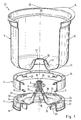
- FIG. 1 shows an exploded perspective view of an advantageous embodiment of a working container 31 according to the invention, which is shown in Fig. 2 in a partially assembled state is.
- the working container 31 essentially consists of a container body 1, a container base 2, a metal apron 4 and a cover sleeve 7 shown in FIG. 2 are formed.
- a container lid 8 is also provided, as shown in FIG. 3.
- the essentially hollow cylindrical container body 1 has according to FIGS. 1 and 2 a container wall 10 and on its underside a channel-shaped container bottom 11 on. In the direction of the container center axis 32, the container bottom 11 gradually rises and forms a protuberance 12 which opens into a circular bottom opening 13. This floor opening 13 has an internal toothing 30.
- the container body has at its upper open end 1 on a container edge 14 which is integrally formed with the container body 1 is.
- the container body 1 is designed as a one-piece deep-drawn part made of stainless steel and is punched out in the area of the bottom opening 13.
- the container base 2 is an injection molded part made of a suitable thermoplastic manufactured. According to Figures 1 and 2, it has an annular shelf 21, the upper edge serves as a metal apron support 19.
- the slightly gutter-shaped top of the container base 2 rises in the direction of the container central axis 32 to a cone 18 on, in a vertically protruding bushing 3 for a tool shaft empties.
- At the bottom of the trough-shaped surface of the container base 2 is formed a concentric to the shelf 21 holding edge 22, the one has a smaller radius than the shelf 21.
- This holding edge 22 has locking receptacles 15 on, which as recesses for receiving on a food processor (Not shown) attached holding elements (not shown) are formed, such as this is the case with the "Braun Multisystem.” K1000 "(see Braun catalog” Quality in good shape ", edition 1999/2000) is the case.
- An annular metal apron 4 is made as a deep-drawn part made of stainless steel. At her top The metal apron 4 has holding tabs 20 distributed over the circumference each have an L-shaped cross-section. The metal apron 4 sits slightly with its upper inside bevelled edge 34 on the metal apron support 19 of the container base 2. The holding tabs 20 engage in the holding tab receptacles 23. By twisting the metal apron 4 in a clockwise direction, this becomes in relation to the container body central axis 32 axially locked.
- the container bottom 11 there are welding tabs 5 corresponding to the retaining tabs 20 connected by spot welding.
- the container body 1 is after attaching the welding tabs 5 polished to remove contact points created by welding.
- the container body 1 and the container base 2 are brought together so that the internal teeth 30 of the bottom opening 13 with the external toothing 17 of the bushing 3 is engaged.
- the metal apron 4 and the welding tabs 5 are so positioned to each other that they can be connected to each other by spot welding.
- a sealing ring 6 which as an O-ring made of rubber or an otherwise elastic Sealing material is provided.
- This sealing ring 6 is below the bottom opening 13 is arranged on the bushing 3 and is from the outside surround the slip 12 on the container bottom 11.
- the component assembled in this way is in Fig. 2 shown.
- a cover sleeve 7 is placed on the bushing 3.
- the cover sleeve 7 has a circumferential groove 25 on its lower conical edge, which covers the upper edge of the protuberance 12 formed on the container bottom 11. there the cover sleeve 7 is welded to the bushing 3.
- the Cover sleeve 7 can also be glued or screwed to the bushing 3.
- the container body 1 has locking lugs 28 on its upper inner circumference that protrude radially inwards. These locking lugs 28 are used to engage in on the container lid 8 arranged locking slots 29, as shown in Fig. 3.
- the Container lid 8 can be locked like a bayonet lock. Further points the container lid 8 an eccentrically arranged feed shaft 9 through the corresponding Food can be fed to the working container. Because of the simple and clear shape of the container lid 8 and the low structure of the feed shaft 9, the container lid 8 is also easy to put in the dishwasher or by hand clean. To prevent filled food from falling onto the agitator, is inside of the feed shaft 9 a cover wall is provided. This ensures that the food supplied goes directly into the working area of the tools.
- the work container is locked on a food processor via the holding edge 22.
- a working shaft rotatably mounted in the bushing 3 (not shown) is through a through hole arranged at the lower end of the bushing 3 27 passed and stored in the shaft bearing 16.
- the shaft bearing 16 is as Plain bearings executed, elongated lubrication pockets 35 are provided.
- the working container 31 stands on its storage rim 21 during operation. Furthermore is on the container body 1 at its upper open end an asymmetrically trained Container edge 14 provided that the assembly of the working container 31 on the food processor allowed only in a predetermined position.
- the container edge 14 also meets the Function of a handle, which makes the work container 31 easier to handle.
Landscapes
- Engineering & Computer Science (AREA)
- Mechanical Engineering (AREA)
- Food Science & Technology (AREA)
- Food-Manufacturing Devices (AREA)
- Closures For Containers (AREA)
- General Preparation And Processing Of Foods (AREA)
Claims (13)
- Cuve fonctionnelle (31) pour un robot ménager, cette dernière présentant un corps de cuve (1) avec une paroi (10) et un fond (11) en métal, une embase de cuve (2) et une douille de traversée (3) pour l'axe d'un outil,
caractérisée en ce que un tablier métallique (4), entourant l'embase de la cuve (2) et par l'intermédiaire duquel le corps de la cuve (1) est relié avec l'embase de la cuve (2) est prévu. - Cuve fonctionnelle pour un robot ménager selon la revendication 1
caractérisée en ce que le tablier métallique (4) est verrouillé ave l'embase de la cuve (2) à l'aide d'une fermeture à baïonnette. - Cuve fonctionnelle pour un robot ménager selon l'une quelconque des revendications 1 ou 2,
caractérisée en ce que sur le fond (11), le corps de la cuve (1) est relié par points de soudure à des languettes à souder (5). - Cuve fonctionnelle pour un robot ménager selon l'une quelconque des revendications précédentes,
caractérisée en ce que la douille de traversée (3) présente sur son extrémité supérieure une denture externe (17) destinée à s'engrener dans la denture interne (30) de l'orifice du fond (13). - Cuve fonctionnelle pour un robot ménager selon la revendication 4,
caractérisée en ce que la denture externe (17) ne peut être amenée à s'engrener avec la denture interne (30) que dans une position prédéfinie. - Cuve fonctionnelle pour un robot ménager selon l'une quelconque des revendications précédentes,
caractérisée en ce que un bord de maintien annulaire (22) destiné à verrouiller le cuve fonctionnelle sur le robot ménager est prévu sur l'embase de la cuve (2). - Cuve fonctionnelle pour un robot ménager selon l'une quelconque des revendications précédentes,
caractérisée en ce que l'embase de la cuve (2) est fabriquée sous forme de pièce moulée par injection. - Cuve fonctionnelle pour un robot ménager selon l'une quelconque des revendications précédentes,
caractérisée en ce que la douille de traversée (3) peut réceptionner un palier lisse destiné à loger un axe d'outil. - Cuve fonctionnelle pour un robot ménager selon l'une quelconque des revendications précédentes,
caractérisée en ce que le bord de la cuve (14) est conçu de façon à ce que la cuve fonctionnelle ne puisse être montée que dans une position prédéfinie. - Cuve fonctionnelle pour un robot ménager selon l'une quelconque des revendications précédentes,
caractérisée en ce qu'une bague d'étanchéité (6) est prévue entre la douille de traversée (3) et une collerette (12) ménagée sur le fond de la cuve (11). - Cuve fonctionnelle pour un robot ménager selon la revendication 10,
caractérisée en ce qu'une douille de recouvrement (7) est prévue sous forme de pièce à rapporter sur la douille de traversée (3). - Cuve fonctionnelle pour un robot ménager selon l'une quelconque des revendications précédentes,
caractérisée en ce que la douille de recouvrement (7) est reliée par gravité avec la douille de traversée (3). - Procédé de fabrication d'une cuve fonctionnelle pour un robot ménager, constitué d'un corps de cuve avec une paroi et un fond en métal, d'une embase de cuve (2) en matière plastique, d'une douille de traversée centrale (3) pour un palier lisse et d'un tablier métallique (4), présentant les étapes suivantes :Fixation de languettes à souder (5) sur le fond de la cuve (11), par points de soudure ; polissage du corps de la cuve (1) ;Verrouillage du tablier métallique (4) avec l'embase de la cuve (2) ;Application d'un joint torique sur la douille de traversée (3) ;Insertion de la douille de traversée (3) dans l'orifice ménagé dans le fond (13) du corps de la cuve (1) ;Fixation des languettes à souder (5) sur le tablier métallique (4) par soudage, de préférence par points de soudure ; etMontage d'une douille de recouvrement (7) de la face interne de la cuve et liaison par gravité de cette dernière avec la douille de traversée.
Applications Claiming Priority (2)
| Application Number | Priority Date | Filing Date | Title |
|---|---|---|---|
| DE10003448 | 2000-01-27 | ||
| DE10003448A DE10003448A1 (de) | 2000-01-27 | 2000-01-27 | Arbeitsbehälter für eine Küchenmaschine |
Publications (2)
| Publication Number | Publication Date |
|---|---|
| EP1120073A1 EP1120073A1 (fr) | 2001-08-01 |
| EP1120073B1 true EP1120073B1 (fr) | 2004-04-21 |
Family
ID=7628860
Family Applications (1)
| Application Number | Title | Priority Date | Filing Date |
|---|---|---|---|
| EP00125171A Expired - Lifetime EP1120073B1 (fr) | 2000-01-27 | 2000-11-18 | Bol pour appareil électroménager |
Country Status (3)
| Country | Link |
|---|---|
| EP (1) | EP1120073B1 (fr) |
| AT (1) | ATE264645T1 (fr) |
| DE (2) | DE10003448A1 (fr) |
Families Citing this family (5)
| Publication number | Priority date | Publication date | Assignee | Title |
|---|---|---|---|---|
| DE10244717B4 (de) * | 2002-09-25 | 2014-11-13 | BSH Bosch und Siemens Hausgeräte GmbH | Haushaltsgerät |
| DE102005060372B4 (de) * | 2005-12-16 | 2008-04-30 | BSH Bosch und Siemens Hausgeräte GmbH | Gefäß mit Fußelement |
| DE102007043726B4 (de) * | 2007-09-13 | 2011-12-01 | BSH Bosch und Siemens Hausgeräte GmbH | Verwindungssteife Rührschüssel |
| CN202589338U (zh) * | 2012-02-28 | 2012-12-12 | 泓首翔电器(深圳)有限公司 | 食物处理器及其刀座组件 |
| CN109381084B (zh) * | 2018-10-31 | 2024-07-02 | 长沙易爱智能科技有限公司 | 一种自动化厨房系统 |
Family Cites Families (4)
| Publication number | Priority date | Publication date | Assignee | Title |
|---|---|---|---|---|
| DE3148067A1 (de) * | 1981-12-04 | 1983-06-09 | Bernhart 8000 München Leitner | Verbindungsstueck zum antriebsmaessigen verbinden eines mixbehaelters mit einem antriebsaggregat |
| DE3404233A1 (de) * | 1984-02-07 | 1985-08-14 | Bosch Siemens Hausgeraete | Zerkleinerungs- und ruehrvorrichtung fuer lebensmittel |
| DE19539382C1 (de) * | 1995-10-23 | 1997-01-23 | Edison Fatehpour | Küchenmixer |
| DE19721302C2 (de) * | 1997-05-21 | 2003-01-09 | Bsh Bosch Siemens Hausgeraete | Arbeitsschüssel für eine motorische Küchenmaschine |
-
2000
- 2000-01-27 DE DE10003448A patent/DE10003448A1/de not_active Withdrawn
- 2000-11-18 EP EP00125171A patent/EP1120073B1/fr not_active Expired - Lifetime
- 2000-11-18 AT AT00125171T patent/ATE264645T1/de not_active IP Right Cessation
- 2000-11-18 DE DE50006144T patent/DE50006144D1/de not_active Expired - Fee Related
Also Published As
| Publication number | Publication date |
|---|---|
| DE10003448A1 (de) | 2001-08-09 |
| DE50006144D1 (de) | 2004-05-27 |
| ATE264645T1 (de) | 2004-05-15 |
| EP1120073A1 (fr) | 2001-08-01 |
Similar Documents
| Publication | Publication Date | Title |
|---|---|---|
| DE69718876T2 (de) | Entnahmeverschluss und Verfahren zu seiner Herstellung | |
| DE3650511T2 (de) | Verfahren zur Herstellung eines Waschmaschinenbehälters und mittels eines solchen Verfahrens hergestellter Behälter | |
| EP1912818B1 (fr) | Tubulure de remplissage pour recipient | |
| EP3797638A1 (fr) | Pot de crème | |
| EP3045346B1 (fr) | Armature reglable | |
| EP0631923B1 (fr) | Bouchon | |
| DE69915291T2 (de) | Abgabevorrichtung für fliessfähige Produkte | |
| EP3919354B1 (fr) | Bouchon d'obturation | |
| EP2298144B1 (fr) | Récipient, notamment récipient de mélange pour une machine de cuisine | |
| EP4197409A1 (fr) | Module d'anneau de broyage pour une reproductibilité améliorée du broyage | |
| EP1120073B1 (fr) | Bol pour appareil électroménager | |
| EP0292664B1 (fr) | Outil pour la préparation des aliments | |
| DE102004035013B3 (de) | Verriegelungssystem für eine Tankeinfüllmulde | |
| DE2335469A1 (de) | Antriebsgestaenge, insbesondere fuer scheibenreinigungsanlagen in kraftfahrzeugen | |
| DE102021126301A1 (de) | Aufsatz für eine Küchenmaschine, Anordnung eines Aufsatzes auf einer Küchenmaschine sowie Verfahren zur Verbindung des Aufsatzes mit einem Deckel | |
| EP0842627B1 (fr) | Outil à mélanger, pétrir ou couper pour un appareil de cuisine | |
| EP0308679B1 (fr) | Récipient en plastique avec une anse moulée | |
| DE69804574T2 (de) | Behälter-Vorrichtung mit abnehmbarem Kragen | |
| DE19721302C2 (de) | Arbeitsschüssel für eine motorische Küchenmaschine | |
| DE69816827T2 (de) | Aufsteckbarer Schaltknopf | |
| EP4376686B1 (fr) | Accessoire de robot ménager, agencement d'un accessoire sur un robot ménager et procédé de liaison de l'accessoire à un couvercle | |
| DE202021106609U1 (de) | Aufsatz für ein Küchengerät und Küchengerät | |
| DE102007049217B4 (de) | Kunststoff-Verschlusselement insbesondere für eine Kosmetikflasche, Adapter für die Anordnung an ein Koppelelement zur Ausbildung eines Kunststoff-Verschlusselements sowie ein Kunststoff-Verschlusselement-Sortiment | |
| DE1124208B (de) | Ruehrwerk fuer Kuechenmaschinen | |
| EP1504703A1 (fr) | Récipients chauffants électriques et procédé pour sa fabrication |
Legal Events
| Date | Code | Title | Description |
|---|---|---|---|
| PUAI | Public reference made under article 153(3) epc to a published international application that has entered the european phase |
Free format text: ORIGINAL CODE: 0009012 |
|
| AK | Designated contracting states |
Kind code of ref document: A1 Designated state(s): AT BE CH CY DE DK ES FI FR GB GR IE IT LI LU MC NL PT SE TR |
|
| AX | Request for extension of the european patent |
Free format text: AL;LT;LV;MK;RO;SI |
|
| 17P | Request for examination filed |
Effective date: 20010814 |
|
| AKX | Designation fees paid |
Free format text: AT BE CH CY DE DK ES FI FR GB GR IE IT LI LU MC NL PT SE TR |
|
| GRAP | Despatch of communication of intention to grant a patent |
Free format text: ORIGINAL CODE: EPIDOSNIGR1 |
|
| GRAS | Grant fee paid |
Free format text: ORIGINAL CODE: EPIDOSNIGR3 |
|
| GRAA | (expected) grant |
Free format text: ORIGINAL CODE: 0009210 |
|
| AK | Designated contracting states |
Kind code of ref document: B1 Designated state(s): AT BE CH CY DE DK ES FI FR GB GR IE IT LI LU MC NL PT SE TR |
|
| PG25 | Lapsed in a contracting state [announced via postgrant information from national office to epo] |
Ref country code: IT Free format text: LAPSE BECAUSE OF FAILURE TO SUBMIT A TRANSLATION OF THE DESCRIPTION OR TO PAY THE FEE WITHIN THE PRE;WARNING: LAPSES OF ITALIAN PATENTS WITH EFFECTIVE DATE BEFORE 2007 MAY HAVE OCCURRED AT ANY TIME BEFORE 2007. THE CORRECT EFFECTIVE DATE MAY BE DIFFERENT FROM THE ONE RECORDED.SCRIBED TIME-LIMIT Effective date: 20040421 Ref country code: IE Free format text: LAPSE BECAUSE OF FAILURE TO SUBMIT A TRANSLATION OF THE DESCRIPTION OR TO PAY THE FEE WITHIN THE PRESCRIBED TIME-LIMIT Effective date: 20040421 Ref country code: FI Free format text: LAPSE BECAUSE OF FAILURE TO SUBMIT A TRANSLATION OF THE DESCRIPTION OR TO PAY THE FEE WITHIN THE PRESCRIBED TIME-LIMIT Effective date: 20040421 Ref country code: FR Free format text: LAPSE BECAUSE OF FAILURE TO SUBMIT A TRANSLATION OF THE DESCRIPTION OR TO PAY THE FEE WITHIN THE PRESCRIBED TIME-LIMIT Effective date: 20040421 Ref country code: NL Free format text: LAPSE BECAUSE OF FAILURE TO SUBMIT A TRANSLATION OF THE DESCRIPTION OR TO PAY THE FEE WITHIN THE PRESCRIBED TIME-LIMIT Effective date: 20040421 Ref country code: TR Free format text: LAPSE BECAUSE OF FAILURE TO SUBMIT A TRANSLATION OF THE DESCRIPTION OR TO PAY THE FEE WITHIN THE PRESCRIBED TIME-LIMIT Effective date: 20040421 Ref country code: GB Free format text: LAPSE BECAUSE OF FAILURE TO SUBMIT A TRANSLATION OF THE DESCRIPTION OR TO PAY THE FEE WITHIN THE PRESCRIBED TIME-LIMIT Effective date: 20040421 Ref country code: CY Free format text: LAPSE BECAUSE OF FAILURE TO SUBMIT A TRANSLATION OF THE DESCRIPTION OR TO PAY THE FEE WITHIN THE PRESCRIBED TIME-LIMIT Effective date: 20040421 |
|
| REG | Reference to a national code |
Ref country code: GB Ref legal event code: FG4D Free format text: NOT ENGLISH |
|
| REG | Reference to a national code |
Ref country code: CH Ref legal event code: NV Representative=s name: LUCHS & PARTNER PATENTANWAELTE Ref country code: CH Ref legal event code: EP |
|
| REG | Reference to a national code |
Ref country code: IE Ref legal event code: FG4D Free format text: GERMAN |
|
| REF | Corresponds to: |
Ref document number: 50006144 Country of ref document: DE Date of ref document: 20040527 Kind code of ref document: P |
|
| PG25 | Lapsed in a contracting state [announced via postgrant information from national office to epo] |
Ref country code: DK Free format text: LAPSE BECAUSE OF FAILURE TO SUBMIT A TRANSLATION OF THE DESCRIPTION OR TO PAY THE FEE WITHIN THE PRESCRIBED TIME-LIMIT Effective date: 20040721 Ref country code: GR Free format text: LAPSE BECAUSE OF FAILURE TO SUBMIT A TRANSLATION OF THE DESCRIPTION OR TO PAY THE FEE WITHIN THE PRESCRIBED TIME-LIMIT Effective date: 20040721 Ref country code: SE Free format text: LAPSE BECAUSE OF FAILURE TO SUBMIT A TRANSLATION OF THE DESCRIPTION OR TO PAY THE FEE WITHIN THE PRESCRIBED TIME-LIMIT Effective date: 20040721 |
|
| PG25 | Lapsed in a contracting state [announced via postgrant information from national office to epo] |
Ref country code: ES Free format text: LAPSE BECAUSE OF FAILURE TO SUBMIT A TRANSLATION OF THE DESCRIPTION OR TO PAY THE FEE WITHIN THE PRESCRIBED TIME-LIMIT Effective date: 20040801 |
|
| NLV1 | Nl: lapsed or annulled due to failure to fulfill the requirements of art. 29p and 29m of the patents act | ||
| GBV | Gb: ep patent (uk) treated as always having been void in accordance with gb section 77(7)/1977 [no translation filed] |
Effective date: 20040421 |
|
| PG25 | Lapsed in a contracting state [announced via postgrant information from national office to epo] |
Ref country code: AT Free format text: LAPSE BECAUSE OF NON-PAYMENT OF DUE FEES Effective date: 20041118 Ref country code: LU Free format text: LAPSE BECAUSE OF NON-PAYMENT OF DUE FEES Effective date: 20041118 |
|
| PG25 | Lapsed in a contracting state [announced via postgrant information from national office to epo] |
Ref country code: BE Free format text: LAPSE BECAUSE OF NON-PAYMENT OF DUE FEES Effective date: 20041130 Ref country code: MC Free format text: LAPSE BECAUSE OF NON-PAYMENT OF DUE FEES Effective date: 20041130 Ref country code: LI Free format text: LAPSE BECAUSE OF NON-PAYMENT OF DUE FEES Effective date: 20041130 Ref country code: CH Free format text: LAPSE BECAUSE OF NON-PAYMENT OF DUE FEES Effective date: 20041130 |
|
| REG | Reference to a national code |
Ref country code: IE Ref legal event code: FD4D |
|
| PLBE | No opposition filed within time limit |
Free format text: ORIGINAL CODE: 0009261 |
|
| STAA | Information on the status of an ep patent application or granted ep patent |
Free format text: STATUS: NO OPPOSITION FILED WITHIN TIME LIMIT |
|
| EN | Fr: translation not filed | ||
| 26N | No opposition filed |
Effective date: 20050124 |
|
| BERE | Be: lapsed |
Owner name: *BRAUN G.M.B.H. Effective date: 20041130 |
|
| PG25 | Lapsed in a contracting state [announced via postgrant information from national office to epo] |
Ref country code: DE Free format text: LAPSE BECAUSE OF NON-PAYMENT OF DUE FEES Effective date: 20050601 |
|
| REG | Reference to a national code |
Ref country code: CH Ref legal event code: PL |
|
| BERE | Be: lapsed |
Owner name: *BRAUN G.M.B.H. Effective date: 20041130 |
|
| PG25 | Lapsed in a contracting state [announced via postgrant information from national office to epo] |
Ref country code: PT Free format text: LAPSE BECAUSE OF NON-PAYMENT OF DUE FEES Effective date: 20040921 |