EP1120076A1 - Staub- und Abfallentfernungsgerät - Google Patents
Staub- und Abfallentfernungsgerät Download PDFInfo
- Publication number
- EP1120076A1 EP1120076A1 EP01200162A EP01200162A EP1120076A1 EP 1120076 A1 EP1120076 A1 EP 1120076A1 EP 01200162 A EP01200162 A EP 01200162A EP 01200162 A EP01200162 A EP 01200162A EP 1120076 A1 EP1120076 A1 EP 1120076A1
- Authority
- EP
- European Patent Office
- Prior art keywords
- opening
- section
- flow cross
- bypass duct
- suction
- Prior art date
- Legal status (The legal status is an assumption and is not a legal conclusion. Google has not performed a legal analysis and makes no representation as to the accuracy of the status listed.)
- Granted
Links
- 239000000428 dust Substances 0.000 title claims abstract description 16
- 239000004744 fabric Substances 0.000 description 7
- 238000004140 cleaning Methods 0.000 description 4
- 230000008901 benefit Effects 0.000 description 3
- 238000006073 displacement reaction Methods 0.000 description 3
- 230000009471 action Effects 0.000 description 2
- 230000009467 reduction Effects 0.000 description 2
- 230000008859 change Effects 0.000 description 1
- 230000003247 decreasing effect Effects 0.000 description 1
- 239000006185 dispersion Substances 0.000 description 1
- 230000007717 exclusion Effects 0.000 description 1
- 238000009408 flooring Methods 0.000 description 1
- 238000004519 manufacturing process Methods 0.000 description 1
- 239000004579 marble Substances 0.000 description 1
Images


Classifications
-
- A—HUMAN NECESSITIES
- A47—FURNITURE; DOMESTIC ARTICLES OR APPLIANCES; COFFEE MILLS; SPICE MILLS; SUCTION CLEANERS IN GENERAL
- A47L—DOMESTIC WASHING OR CLEANING; SUCTION CLEANERS IN GENERAL
- A47L9/00—Details or accessories of suction cleaners, e.g. mechanical means for controlling the suction or for effecting pulsating action; Storing devices specially adapted to suction cleaners or parts thereof; Carrying-vehicles specially adapted for suction cleaners
- A47L9/02—Nozzles
- A47L9/04—Nozzles with driven brushes or agitators
- A47L9/0405—Driving means for the brushes or agitators
- A47L9/0416—Driving means for the brushes or agitators driven by fluid pressure, e.g. by means of an air turbine
-
- A—HUMAN NECESSITIES
- A47—FURNITURE; DOMESTIC ARTICLES OR APPLIANCES; COFFEE MILLS; SPICE MILLS; SUCTION CLEANERS IN GENERAL
- A47L—DOMESTIC WASHING OR CLEANING; SUCTION CLEANERS IN GENERAL
- A47L9/00—Details or accessories of suction cleaners, e.g. mechanical means for controlling the suction or for effecting pulsating action; Storing devices specially adapted to suction cleaners or parts thereof; Carrying-vehicles specially adapted for suction cleaners
- A47L9/02—Nozzles
- A47L9/04—Nozzles with driven brushes or agitators
- A47L9/0427—Gearing or transmission means therefor
- A47L9/0444—Gearing or transmission means therefor for conveying motion by endless flexible members, e.g. belts
Definitions
- the present invention relates to a device for removing dust and rubbish from a surface, for example a fabric surface, such as a moquette, carpet and the like, or from a bare surface, such as a tiled, marble, wooden (parquet) and similar type of floor.
- a surface for example a fabric surface, such as a moquette, carpet and the like, or from a bare surface, such as a tiled, marble, wooden (parquet) and similar type of floor.
- the turbo-brush head includes a rotating brush provided with bristles and actuated by a turbine with radial vanes.
- the rotating brush and the turbine are rotatably supported in two housings inside a casing.
- the casing has a suction opening, inside which the rotating brush is placed, and a suction nozzle located between the rotating brush and the turbine.
- a suction pipe connected to a suction device communicates with the suction nozzle and the turbine housing.
- the simple suction head in turn, includes its own suction opening which is placed in communication with the suction pipe connected to the suction device.
- JP-06098840 discloses a vacuum cleaner having a suction air flow which is turned into a jet flow after passing through a nozzle to rotate an impeller and then it is turned into an exhaust air flow. Rotation of the impeller of the turbine rotates a rotary brush through a timing belt.
- a main nozzle and a bypass nozzle are positioned on a nozzle supporting plate and the cross-sectional shape of the nozzle is made into a circular form or an elliptic form.
- a plate shutter is engageable with the bypass nozzle to close it.
- the main nozzle is used for a heavy loading such as a carpet and the bypass nozzle is used for a relatively light loading such as a tatami mat or a wooden flooring.
- the circular or elliptic form of the nozzle has the purpose of decreasing the sound of the air flow.
- the turbine and the rotary brush are always active, since the steps of opening and closing the bypass nozzle have only the aim of adjusting the air flow directed on the turbine.
- said vacuum cleaner always operates as a turbo-brush head and never can operate only as a suction head.
- the object of the present invention is to provide a device which is capable of performing both the functions and which is easy and inexpensive to manufacture.
- a device for removing dust and rubbish from a surface comprising a casing provided with a suction opening, a rotating brush, a turbine operationally connected to said brush, a suction nozzle having a predefined flow cross-section, and a suction pipe connected to a suction device, said rotating brush having a shaft rotatably supported in a first housing of said casing, said turbine having a shaft rotatably supported in a second housing of said casing, said suction nozzle being located between said rotating brush and said turbine for sucking an air flow from said suction opening, direct it onto said rotating brush and then towards said turbine, characterized in that said device also includes at least a bypass duct and first valve means, said at least a bypass duct having a predefined flow cross-section and being designed for bypassing said second housing and said turbine, and connecting said suction opening and said first housing with said suction pipe and said suction device, said first valve means being able to engage with said suction nozzle and with said at least a bypass
- opening of said bypass together with the simultaneous closing of said suction nozzle, deactivates said turbine and said rotating brush and causes said device to operate as a suction head only.
- opening of said suction nozzle together with simultaneous closing of said bypass, activates said turbine and said rotating brush and causes said device to operate as a turbo-brush head.
- said first valve means are able to vary gradually said flow cross-section of said suction nozzle.
- said first valve means are able to vary gradually said flow cross-section of said at least a bypass duct.
- said first valve means are able to close gradually said flow cross-section of said suction nozzle, while they gradually open said flow cross-section of said at least a bypass duct.
- said first valve means are connected to a manual actuating element.
- said first valve means consist of a first slide valve having a first sliding shutter provided with a first opening able to be superimposed on said flow cross-section of said suction nozzle.
- said first sliding shutter is further provided with a second opening able to be superimposed on said flow cross-section of said at least a bypass duct.
- said first and second opening of said first sliding shutter have a width greater than the width of said flow cross-section of said suction nozzle and, respectively, of said flow cross-section of said at least a bypass duct.
- said device also includes an auxiliary opening which connects said first housing to the external environment and second valve means able to engage with said auxiliary opening for opening it when said turbine undergoes a drop in power owing to obstruction of said suction opening, for example by a moquette or a carpet.
- said second valve means consist of a second slide valve having a second sliding shutter provided with a third opening designed to be superimposed on said auxiliary opening.
- said first and second sliding shutter are operationally connected to a slider.
- said shaft of said rotating brush is also movably supported in said first housing and is operationally connected to actuating means capable of raising it and keeping it raised so as to move said rotating brush away from said surface to be cleaned.
- said actuating means include two levers which rotatably support said shaft of said rotating brush, said two levers being pivotably mounted in said first housing.
- said actuating means also include a projecting element integral with said levers, said first sliding shutter being provided with a ramp and a surface which engage with said projecting element, raising it and causing it to rotate integrally with said levers for raising said rotating brush and keeping it raised.
- said first opening of said first sliding shutter is able to be superimposed on the said flow cross-section of said suction nozzle and/or on said flow cross-section of said at least a bypass duct.
- said first opening of said first shutter has a width greater than the width of said flow cross-section of said suction nozzle and substantially equal to the width of said flow cross-section of said at least a bypass duct.
- said bypass duct is placed under said second housing.
- a first and a second bypass duct are placed at the sides of said second housing.
- said first sliding shutter is provided with a lateral portion able to be superimposed on said flow cross-section of said second bypass duct, while said first opening is able to be superimposed on said flow cross-section of said suction nozzle and/or on said flow cross-section of said first bypass duct.
- the device according to the invention offers the advantage that it may be used both as a turbo-brush head for cleaning a moquette, a carpet and the like, and as a simple suction head for cleaning a bare surface.
- the device is particularly efficient because the exclusion of the turbine from the path of the air which flows from the suction opening to the suction device does not produce that dispersion of energy which occurs when the sucked air flow interacts with the turbine.
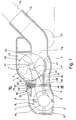
- Fig. 1 shows a device 1 having a casing 2 provided with wheels 21 and 20.
- the device 1 includes a rotating brush 8 provided with bristles 9.
- the rotating brush 8 has a shaft 40 rotatably supported in a housing 7 of the casing 2.
- the brush 8 is rotated, in an anti-clockwise direction, by a turbine 11 via a toothed belt 17 and toothed pulleys, not shown.
- the turbine 11 has a shaft 41 and a rotor 42 provided with radial vanes 43.
- the shaft 41 of the turbine 11 is rotatably supported in a housing 12 in the casing 2.
- a suction pipe 14, which is fixed to a union 13 of the casing 2 is connected to a suction device not shown, in that it is known to the person skilled in the art.
- the union 13 also communicates with the housing 12 of the turbine 11 via an opening 19.
- the casing 2 is provided with a suction opening 5 inside which the rotating brush 8 is arranged and has a sliding base 3 which makes contact with a surface to be cleaned 4.
- a suction nozzle 15 having a predefined flow cross-section, is located between the housing 7 of the rotating brush 8 and the housing 12 of the turbine 11.
- the nozzle 15 has an inlet port 6 communicating with the housing 7 of the rotating brush 8 and an outlet port 44 which emerges in the vicinity of the bottom vanes 43 of the turbine 11.
- a duct 45 for bypassing the housing 12 of the turbine 11 is placed in the lower zone of the casing 2, under the housing 12.
- the bypass duct 45 has a predefined flow cross-section and has an inlet port 46 communicating with the housing 7 of the rotating brush 8 and an outlet port 47 communicating with the union 13 and the suction pipe 14.
- the bypass duct 45 directly connects the housing 7 of the rotating brush 8 with the union 13 and the suction pipe 14.
- a slide valve 22 has a plate-like shutter 48 which engages with the suction nozzle 15 and the bypass duct 45.
- the shutter 48 is mounted inside a guide channel 49 and is slidable in a transverse direction.
- the sliding shutter 48 has two openings 18 and 23 (Figs. 2 and 4).
- the opening 18 is designed to be superimposed on the inlet port 6 of the suction nozzle 15 and to connect the housing 7 of the brush 8 to the nozzle 15.
- the opening 23 is designed to be superimposed on the inlet port 46 of the bypass duct 45 and to connect the housing 7 of the brush 8 to the bypass duct 45.
- the sliding shutter 48 is provided with a tongue 50 which emerges from a transverse slot 51 in the casing 2 and is fixed to a slider 52 which can be actuated manually by the person using the device 1.
- the slider 52 is integral with a slide valve 55 provided with a sliding shutter 53 which engages with an auxiliary opening 31 in the casing 2.
- the shutter 53 has an opening 54 (Figs. 3 and 5) which is designed to be superimposed on the auxiliary opening 31 and connect the housing 7 of the rotating brush 8 to the external environment.
- the shaft 40 of the rotating brush 8 is provided with two end pins 24 and bushes 25 (only one of which is shown in Fig. 7) by means of which it is rotatably supported on the outer ends of two levers 26.
- the levers 26 are pivotably mounted, at their inner ends, in seats 28 in the housing 7 by means of a rod 33 which renders them integral.
- the rod 33 is provided with a projecting element 34, for example a cam, with which a ramp 35 and a surface 36 of the sliding shutter 48 of the slide valve 22 engage, as will be illustrated further below.
- Fig. 1 shows the configuration of the device 1 when it is used as a turbo-brush head for cleaning fabric surfaces, such as moquettes, carpets and the like.
- an operator using the device 1 actuates the slider 52 (arrow A in Fig. 4) and adjusts the sliding shutter 48 of the slide valve 22 in a position where its opening 18 is superimposed on the inlet port 6 of the suction nozzle 15 and the suction nozzle 15 is completely open. In this position, the shutter 48 closes the inlet port 46 of the bypass duct 45.
- the bristles 9 of the rotating brush 8 project from the suction opening 5 and, with their rotary movement, raise the dust and rubbish present on the surface to be cleaned, facilitating suction thereof.
- a further advantage of the present invention is that, when the operator wishes to cause operation of the rotating brush 8 at a speed of rotation lower than the maximum speed, for example in order to clean valuable or delicate fabrics, he/she actuates the shutter 48 of the slide valve 22 by means of the slider 52 and displaces it in a position where the opening 18 is partly superimposed on the inlet port 6 of the suction nozzle 15 and the opening 23 is partly superimposed on the inlet port 46 of the bypass duct 45, depending on the desired reduction in speed. In this way, the flow cross-section of the nozzle 15 is reduced and the air flow which strikes the turbine 11 is proportionally reduced. The remaining part of the air flow, instead, is conveyed to the suction device via the bypass duct 45.Thus, the turbine 11 operates at a speed of rotation less than the maximum speed and the brush 8 rotates at a predefined lower speed.
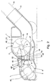
- Fig. 2 shows the configuration of the device 1 when it operates only as a suction head.
- the operator using the device 1 actuates the slider 52 and adjusts the sliding shutter 48 of the slide valve 22 in a position where the opening 18 is displaced from the inlet port 6 of the suction nozzle 15 and the opening 23 is superimposed on the inlet port 46 of the bypass duct 45.
- the suction nozzle 15 is closed and the turbine 11 and the rotating brush 8 are deactivated, while the bypass duct 45 is completely open.
- the air flow which removes the dust and rubbish from the surface to be cleaned is sucked via the opening 5, pass through the housing 7 and is directly conveyed by means of the bypass duct 45 to the union 13 and the suction pipe 14.
- the rotating brush 8 is moved away from the surface 4, as will be illustrated further below.
- Fig. 3 shows the configuration of the device 1 when, during cleaning of surfaces 4 lined with fabric, the rotating brush 8 tends to stop rotating because the fabric to be cleaned is sucked up against the suction opening 5 and obstructs it.
- the operator by means of the slider 52, displaces the shutter 53 and causes the opening 54 to superimpose on the auxiliary opening 31 connecting the housing 7 to the external environment.
- the sliding shutter 48 keeps the inlet port 6 of the suction nozzle 15 open. Via the opening 31 and the suction nozzle 15, a secondary air flow is produced which reaches the turbine 11 and causes it to start operating again.
- Figs. 6 to 8 show the configuration of the device 1 when the rotating brush 8 is raised.
- the sliding shutter 48 is actuated so as to intercept the suction nozzle 15 and leave the bypass 45 open (Fig. 8). While the shutter 48 slides towards the left in the Fig. 8, its ramp 35 comes into contact with the projecting element 34 and raises it, causing it to rotate integrally with the rod 33. The projecting element 34 and the rod 33, in turn, rotate the levers 26 which raise the rotating brush 8 and cause it to move away from the suction opening 5. When the projecting element 34 reaches the surface 36, the levers 26 are locked and keep the rotating brush 8 in the completely raised position.
- Figs. 9 and 10 show a device 100 for removing dust and rubbish where the parts as those of the device 1 are denoted by the same reference numerals.
- the device 100 has a casing 102 including the housing 7 of the rotating brush 8 and the housing 12 of turbine 11. It further includes two ducts 145 and 245 which bypass the housing 12 of the turbine 11 and are placed at the sides of the housing 12 of turbine 11. Both the bypass ducts 145 and 245 directly connect the housing 7 of the rotating brush 8 with a joint 113 and the suction pipe 14.
- the bypass ducts 145 and 245 have respective inlet ports 146 and 246 (Fig. 10) and respective outlet ports 147 and 247.
- a slide valve 122 has a plate-like sliding shutter 148 engageable with the suction nozzle 15 and bypass ducts 145 and 245.
- the shutter 148 slides in a transverse direction (arrow A) and is connected to the slider 52 which is actuated manually by a person using the device 100.
- the slider 52 may be actuated by a conventional motor.
- the sliding shutter 148 has lateral portions 110 and 111 and an intermediate opening 118.
- the opening 118 is designed to be superimposed on the inlet port 6 of the suction nozzle 15 when the operator wants connect the housing 7 of the brush 8 to the suction nozzle 15.
- the lateral portion 111 of sliding shutter 148 is designed to be superimposed to the inlet ports 246 of the bypass duct 245 and to be removed from it for disconnecting and, respectively, connecting the housing 7 to the bypass duct 245.
- the lateral portion 110 is designed to be superimposed to the inlet ports 146 of the bypass duct 145 for disconnecting the housing 7 from the bypass duct 145.
- the opening 118 is also designed to be superimposed on the inlet port 146 of the bypass duct 145 for connecting the housing 7 of the brush 8 to the bypass duct 145.
- the opening 118 is wider than the cross-section of the inlet port 6 and substantially equal to the width of the cross-section of the inlet port 146.
- the device 100 operates as the device 1.
- the operator wants operate the device 100 as a turbo-brush head, he has to adjust the sliding shutter 148 of the slide valve 122 in a position where the opening 118 is superimposed on the inlet port 6 of the suction nozzle 15. In this position of the shutter 148, the suction nozzle 15 is completely open, while the inlet ports 146 and 246 of the bypass ducts 145 and 245 are closed by the lateral portions 110 and 111, respectively (Fig. 10).
- the turbine 11 is active and drives the brush 8.
- the operator wants operate the device 100 as a suction head only, he has to displace the sliding shutter 148 of the slide valve 122 to the left-hand side of arrow A in Fig. 10 till the shutter 148 opens the inlet ports146 and 246 of the bypass ducts 145 and 245, respectively, and closes the inlet port 6 of the suction nozzle 15.
- the inlet port 246 is open thanks to the displacement of the lateral portion 111 on the left, while the inlet port 146 is open thanks to the concurrent displacement of the opening 118 on the inlet port 146.
- the turbine 11 and the rotating brush 8 are thus deactivated and the air flow which removes the dust and rubbish from the surface to be cleaned is sucked via the opening 5, passes through the housing 7 and is directly conveyed by means of the bypass ducts 145 and 245 to the joint 113 and the suction pipe 14.
- the displacement of the sliding shutter 148 in any intermediate positions allows to vary at will the flow cross-section of the inlet ports 6, 146 and 246 of the suction nozzle 15 and of the bypass ducts 145 and 245, respectively. It is thus possible to control the air flows which impact and/or bypass the turbine 11 and the housing 12.
- bypass ducts 145 and 245 at the sides of the housing 12 of the turbine 11 is preferred because it minimizes the height of the device 100 in comparison with that of the device 1.
Landscapes
- Engineering & Computer Science (AREA)
- Mechanical Engineering (AREA)
- Nozzles For Electric Vacuum Cleaners (AREA)
Priority Applications (1)
| Application Number | Priority Date | Filing Date | Title |
|---|---|---|---|
| EP20010200162 EP1120076B1 (de) | 2000-01-28 | 2001-01-17 | Staub- und Abfallentfernungsgerät |
Applications Claiming Priority (3)
| Application Number | Priority Date | Filing Date | Title |
|---|---|---|---|
| EP00830053 | 2000-01-28 | ||
| EP00830053 | 2000-01-28 | ||
| EP20010200162 EP1120076B1 (de) | 2000-01-28 | 2001-01-17 | Staub- und Abfallentfernungsgerät |
Publications (2)
| Publication Number | Publication Date |
|---|---|
| EP1120076A1 true EP1120076A1 (de) | 2001-08-01 |
| EP1120076B1 EP1120076B1 (de) | 2004-04-21 |
Family
ID=26074113
Family Applications (1)
| Application Number | Title | Priority Date | Filing Date |
|---|---|---|---|
| EP20010200162 Expired - Lifetime EP1120076B1 (de) | 2000-01-28 | 2001-01-17 | Staub- und Abfallentfernungsgerät |
Country Status (1)
| Country | Link |
|---|---|
| EP (1) | EP1120076B1 (de) |
Cited By (2)
| Publication number | Priority date | Publication date | Assignee | Title |
|---|---|---|---|---|
| EP1695651A3 (de) * | 2005-02-23 | 2008-01-23 | Samsung Gwangju Electronics Co., Ltd. | Bürstenanordnung für einen Staubsauger |
| GB2441495A (en) * | 2006-09-09 | 2008-03-12 | Vax Ltd | Suction diversion channel in vacuum cleaner head |
Families Citing this family (2)
| Publication number | Priority date | Publication date | Assignee | Title |
|---|---|---|---|---|
| MX2008012044A (es) | 2007-09-19 | 2009-04-15 | Emerson Electric Co | Boquilla para liquido que se une a presion para dispositivo electrodomestico con aspiracion. |
| USD643169S1 (en) | 2010-05-20 | 2011-08-09 | Emerson Electric Co. | Vacuum cleaner floor tool |
Citations (6)
| Publication number | Priority date | Publication date | Assignee | Title |
|---|---|---|---|---|
| EP0315068A2 (de) * | 1987-11-05 | 1989-05-10 | Siegfried Maier | Stelleinrichtung an einer Bürstendüse eines Saugreinigungsgerätes (Staubsauger) |
| JPH01141635A (ja) * | 1987-11-30 | 1989-06-02 | Matsushita Electric Ind Co Ltd | タービンノズル |
| US5008973A (en) * | 1989-01-31 | 1991-04-23 | Dupro Ag | Multi-purpose suction nozzle |
| DE4105012A1 (de) * | 1991-02-19 | 1992-10-22 | Fedag Romanshorn Fa | Staubsaugermundstueck |
| US5249333A (en) * | 1991-02-21 | 1993-10-05 | Firma Fedag | Vacuum cleaning tool |
| JPH0698840A (ja) * | 1992-09-04 | 1994-04-12 | Hitachi Ltd | 電気掃除機 |
-
2001
- 2001-01-17 EP EP20010200162 patent/EP1120076B1/de not_active Expired - Lifetime
Patent Citations (6)
| Publication number | Priority date | Publication date | Assignee | Title |
|---|---|---|---|---|
| EP0315068A2 (de) * | 1987-11-05 | 1989-05-10 | Siegfried Maier | Stelleinrichtung an einer Bürstendüse eines Saugreinigungsgerätes (Staubsauger) |
| JPH01141635A (ja) * | 1987-11-30 | 1989-06-02 | Matsushita Electric Ind Co Ltd | タービンノズル |
| US5008973A (en) * | 1989-01-31 | 1991-04-23 | Dupro Ag | Multi-purpose suction nozzle |
| DE4105012A1 (de) * | 1991-02-19 | 1992-10-22 | Fedag Romanshorn Fa | Staubsaugermundstueck |
| US5249333A (en) * | 1991-02-21 | 1993-10-05 | Firma Fedag | Vacuum cleaning tool |
| JPH0698840A (ja) * | 1992-09-04 | 1994-04-12 | Hitachi Ltd | 電気掃除機 |
Non-Patent Citations (2)
| Title |
|---|
| PATENT ABSTRACTS OF JAPAN vol. 018, no. 367 (C - 1223) 11 July 1994 (1994-07-11) * |
| PATENT ABSTRACTS OF JAPAN vol. 1999, no. 06 31 March 1999 (1999-03-31) * |
Cited By (4)
| Publication number | Priority date | Publication date | Assignee | Title |
|---|---|---|---|---|
| EP1695651A3 (de) * | 2005-02-23 | 2008-01-23 | Samsung Gwangju Electronics Co., Ltd. | Bürstenanordnung für einen Staubsauger |
| GB2441495A (en) * | 2006-09-09 | 2008-03-12 | Vax Ltd | Suction diversion channel in vacuum cleaner head |
| EP1897477A3 (de) * | 2006-09-09 | 2009-04-01 | Vax Limited | Reinigungskopf für einen Staubsauger |
| US7552507B2 (en) | 2006-09-09 | 2009-06-30 | Vax Limited | Cleaning head for a vacuum cleaner |
Also Published As
| Publication number | Publication date |
|---|---|
| EP1120076B1 (de) | 2004-04-21 |
Similar Documents
| Publication | Publication Date | Title |
|---|---|---|
| US6571424B2 (en) | Device for removing dust and rubbish | |
| US11712139B2 (en) | Surface cleaning head with leading roller | |
| JP5433718B2 (ja) | 表面処理ヘッド | |
| JP5600509B2 (ja) | 表面処理ヘッド | |
| EP1452120A1 (de) | Saugreinigungsvorrichtung | |
| AU744362B2 (en) | Changeover valve | |
| JPH04276224A (ja) | 吸塵機の吸引本体部 | |
| EP1468637B1 (de) | Saugreiniger | |
| CN101039616B (zh) | 真空吸尘器吸头 | |
| JP2011019916A (ja) | 表面処理ヘッド | |
| CN107348895B (zh) | 用于清洁地面的装置 | |
| EP1120076B1 (de) | Staub- und Abfallentfernungsgerät | |
| CN101564280A (zh) | 电动吸尘器 | |
| HK1038487B (en) | Device for removing dust and rubbish | |
| HK1038487A1 (en) | Device for removing dust and rubbish | |
| KR100999268B1 (ko) | 진공 청소기 | |
| JP3819559B2 (ja) | 床用吸込具 | |
| KR100504892B1 (ko) | 흡입구의 높이가 가변되는 업라이트 청소기 | |
| JP3558202B2 (ja) | 電気掃除機およびその吸込口体 | |
| JP2005000266A (ja) | 吸込口体及び電気掃除機 | |
| JPH06319670A (ja) | 電気掃除機の吸込口体 | |
| CN112176676A (zh) | 具有为通电附件提供外部气流的附属端口的烘干器具 | |
| JPH11244205A (ja) | 電気掃除機 | |
| JPH04343822A (ja) | 電気掃除機の逆風排気装置 |
Legal Events
| Date | Code | Title | Description |
|---|---|---|---|
| PUAI | Public reference made under article 153(3) epc to a published international application that has entered the european phase |
Free format text: ORIGINAL CODE: 0009012 |
|
| AK | Designated contracting states |
Kind code of ref document: A1 Designated state(s): AT BE CH CY DE DK ES FI FR GB GR IE IT LI LU MC NL PT SE TR |
|
| AX | Request for extension of the european patent |
Free format text: AL;LT;LV;MK;RO;SI |
|
| 17P | Request for examination filed |
Effective date: 20011107 |
|
| AKX | Designation fees paid |
Free format text: AT BE CH CY DE DK ES FI FR GB GR IE IT LI LU MC NL PT SE TR |
|
| GRAP | Despatch of communication of intention to grant a patent |
Free format text: ORIGINAL CODE: EPIDOSNIGR1 |
|
| GRAS | Grant fee paid |
Free format text: ORIGINAL CODE: EPIDOSNIGR3 |
|
| GRAA | (expected) grant |
Free format text: ORIGINAL CODE: 0009210 |
|
| AK | Designated contracting states |
Kind code of ref document: B1 Designated state(s): AT BE CH CY DE DK ES FI FR GB GR IE IT LI LU MC NL PT SE TR |
|
| PG25 | Lapsed in a contracting state [announced via postgrant information from national office to epo] |
Ref country code: FI Free format text: LAPSE BECAUSE OF FAILURE TO SUBMIT A TRANSLATION OF THE DESCRIPTION OR TO PAY THE FEE WITHIN THE PRESCRIBED TIME-LIMIT Effective date: 20040421 Ref country code: NL Free format text: LAPSE BECAUSE OF FAILURE TO SUBMIT A TRANSLATION OF THE DESCRIPTION OR TO PAY THE FEE WITHIN THE PRESCRIBED TIME-LIMIT Effective date: 20040421 |
|
| REG | Reference to a national code |
Ref country code: GB Ref legal event code: FG4D |
|
| REG | Reference to a national code |
Ref country code: CH Ref legal event code: EP |
|
| REG | Reference to a national code |
Ref country code: IE Ref legal event code: FG4D |
|
| REF | Corresponds to: |
Ref document number: 60102842 Country of ref document: DE Date of ref document: 20040527 Kind code of ref document: P |
|
| PG25 | Lapsed in a contracting state [announced via postgrant information from national office to epo] |
Ref country code: SE Free format text: LAPSE BECAUSE OF FAILURE TO SUBMIT A TRANSLATION OF THE DESCRIPTION OR TO PAY THE FEE WITHIN THE PRESCRIBED TIME-LIMIT Effective date: 20040721 Ref country code: GR Free format text: LAPSE BECAUSE OF FAILURE TO SUBMIT A TRANSLATION OF THE DESCRIPTION OR TO PAY THE FEE WITHIN THE PRESCRIBED TIME-LIMIT Effective date: 20040721 Ref country code: DK Free format text: LAPSE BECAUSE OF FAILURE TO SUBMIT A TRANSLATION OF THE DESCRIPTION OR TO PAY THE FEE WITHIN THE PRESCRIBED TIME-LIMIT Effective date: 20040721 |
|
| REG | Reference to a national code |
Ref country code: CH Ref legal event code: NV Representative=s name: E. BLUM & CO. PATENTANWAELTE |
|
| NLV1 | Nl: lapsed or annulled due to failure to fulfill the requirements of art. 29p and 29m of the patents act | ||
| REG | Reference to a national code |
Ref country code: ES Ref legal event code: FG2A Ref document number: 2217085 Country of ref document: ES Kind code of ref document: T3 |
|
| ET | Fr: translation filed | ||
| PG25 | Lapsed in a contracting state [announced via postgrant information from national office to epo] |
Ref country code: LU Free format text: LAPSE BECAUSE OF NON-PAYMENT OF DUE FEES Effective date: 20050117 Ref country code: CY Free format text: LAPSE BECAUSE OF FAILURE TO SUBMIT A TRANSLATION OF THE DESCRIPTION OR TO PAY THE FEE WITHIN THE PRESCRIBED TIME-LIMIT Effective date: 20050117 |
|
| PG25 | Lapsed in a contracting state [announced via postgrant information from national office to epo] |
Ref country code: MC Free format text: LAPSE BECAUSE OF NON-PAYMENT OF DUE FEES Effective date: 20050131 |
|
| PLBE | No opposition filed within time limit |
Free format text: ORIGINAL CODE: 0009261 |
|
| REG | Reference to a national code |
Ref country code: HK Ref legal event code: GR Ref document number: 1038487 Country of ref document: HK |
|
| STAA | Information on the status of an ep patent application or granted ep patent |
Free format text: STATUS: NO OPPOSITION FILED WITHIN TIME LIMIT |
|
| 26N | No opposition filed |
Effective date: 20050124 |
|
| REG | Reference to a national code |
Ref country code: CH Ref legal event code: PFA Owner name: NEW ERMES EUROPE S.P.A. Free format text: NEW ERMES EUROPE S.P.A.#VIA MANZONI, 17#21041 ALBIZZATE (VARESE) (IT) -TRANSFER TO- NEW ERMES EUROPE S.P.A.#VIA MANZONI, 17#21041 ALBIZZATE (VARESE) (IT) |
|
| PG25 | Lapsed in a contracting state [announced via postgrant information from national office to epo] |
Ref country code: PT Free format text: LAPSE BECAUSE OF NON-PAYMENT OF DUE FEES Effective date: 20040921 |
|
| PGFP | Annual fee paid to national office [announced via postgrant information from national office to epo] |
Ref country code: CH Payment date: 20120131 Year of fee payment: 12 Ref country code: IE Payment date: 20120131 Year of fee payment: 12 Ref country code: FR Payment date: 20120206 Year of fee payment: 12 |
|
| PGFP | Annual fee paid to national office [announced via postgrant information from national office to epo] |
Ref country code: DE Payment date: 20120319 Year of fee payment: 12 Ref country code: TR Payment date: 20120116 Year of fee payment: 12 |
|
| PGFP | Annual fee paid to national office [announced via postgrant information from national office to epo] |
Ref country code: GB Payment date: 20120123 Year of fee payment: 12 Ref country code: IT Payment date: 20120120 Year of fee payment: 12 Ref country code: BE Payment date: 20120221 Year of fee payment: 12 |
|
| PGFP | Annual fee paid to national office [announced via postgrant information from national office to epo] |
Ref country code: AT Payment date: 20120126 Year of fee payment: 12 |
|
| PGFP | Annual fee paid to national office [announced via postgrant information from national office to epo] |
Ref country code: ES Payment date: 20120117 Year of fee payment: 12 |
|
| BERE | Be: lapsed |
Owner name: *NEW ERMES EUROPE S.P.A. Effective date: 20130131 |
|
| REG | Reference to a national code |
Ref country code: CH Ref legal event code: PL |
|
| REG | Reference to a national code |
Ref country code: AT Ref legal event code: MM01 Ref document number: 264648 Country of ref document: AT Kind code of ref document: T Effective date: 20130131 |
|
| GBPC | Gb: european patent ceased through non-payment of renewal fee |
Effective date: 20130117 |
|
| REG | Reference to a national code |
Ref country code: IE Ref legal event code: MM4A |
|
| REG | Reference to a national code |
Ref country code: FR Ref legal event code: ST Effective date: 20130930 |
|
| PG25 | Lapsed in a contracting state [announced via postgrant information from national office to epo] |
Ref country code: CH Free format text: LAPSE BECAUSE OF NON-PAYMENT OF DUE FEES Effective date: 20130131 Ref country code: LI Free format text: LAPSE BECAUSE OF NON-PAYMENT OF DUE FEES Effective date: 20130131 Ref country code: BE Free format text: LAPSE BECAUSE OF NON-PAYMENT OF DUE FEES Effective date: 20130131 Ref country code: DE Free format text: LAPSE BECAUSE OF NON-PAYMENT OF DUE FEES Effective date: 20130801 Ref country code: AT Free format text: LAPSE BECAUSE OF NON-PAYMENT OF DUE FEES Effective date: 20130131 |
|
| REG | Reference to a national code |
Ref country code: DE Ref legal event code: R119 Ref document number: 60102842 Country of ref document: DE Effective date: 20130801 |
|
| PG25 | Lapsed in a contracting state [announced via postgrant information from national office to epo] |
Ref country code: GB Free format text: LAPSE BECAUSE OF NON-PAYMENT OF DUE FEES Effective date: 20130117 Ref country code: FR Free format text: LAPSE BECAUSE OF NON-PAYMENT OF DUE FEES Effective date: 20130131 |
|
| PG25 | Lapsed in a contracting state [announced via postgrant information from national office to epo] |
Ref country code: IT Free format text: LAPSE BECAUSE OF NON-PAYMENT OF DUE FEES Effective date: 20130117 |
|
| PG25 | Lapsed in a contracting state [announced via postgrant information from national office to epo] |
Ref country code: IE Free format text: LAPSE BECAUSE OF NON-PAYMENT OF DUE FEES Effective date: 20130117 |
|
| PG25 | Lapsed in a contracting state [announced via postgrant information from national office to epo] |
Ref country code: TR Free format text: LAPSE BECAUSE OF NON-PAYMENT OF DUE FEES Effective date: 20130117 |
|
| REG | Reference to a national code |
Ref country code: ES Ref legal event code: FD2A Effective date: 20140509 |
|
| PG25 | Lapsed in a contracting state [announced via postgrant information from national office to epo] |
Ref country code: ES Free format text: LAPSE BECAUSE OF NON-PAYMENT OF DUE FEES Effective date: 20130118 |