EP1120163B1 - Herstellungsverfahren für einen Metallträger-Katalysator - Google Patents
Herstellungsverfahren für einen Metallträger-Katalysator Download PDFInfo
- Publication number
- EP1120163B1 EP1120163B1 EP01101545A EP01101545A EP1120163B1 EP 1120163 B1 EP1120163 B1 EP 1120163B1 EP 01101545 A EP01101545 A EP 01101545A EP 01101545 A EP01101545 A EP 01101545A EP 1120163 B1 EP1120163 B1 EP 1120163B1
- Authority
- EP
- European Patent Office
- Prior art keywords
- core
- outer cylinder
- solder
- metallic
- inner periphery
- Prior art date
- Legal status (The legal status is an assumption and is not a legal conclusion. Google has not performed a legal analysis and makes no representation as to the accuracy of the status listed.)
- Expired - Lifetime
Links
Images




Classifications
-
- F—MECHANICAL ENGINEERING; LIGHTING; HEATING; WEAPONS; BLASTING
- F01—MACHINES OR ENGINES IN GENERAL; ENGINE PLANTS IN GENERAL; STEAM ENGINES
- F01N—GAS-FLOW SILENCERS OR EXHAUST APPARATUS FOR MACHINES OR ENGINES IN GENERAL; GAS-FLOW SILENCERS OR EXHAUST APPARATUS FOR INTERNAL-COMBUSTION ENGINES
- F01N3/00—Exhaust or silencing apparatus having means for purifying, rendering innocuous, or otherwise treating exhaust
- F01N3/08—Exhaust or silencing apparatus having means for purifying, rendering innocuous, or otherwise treating exhaust for rendering innocuous
- F01N3/10—Exhaust or silencing apparatus having means for purifying, rendering innocuous, or otherwise treating exhaust for rendering innocuous by thermal or catalytic conversion of noxious components of exhaust
- F01N3/24—Exhaust or silencing apparatus having means for purifying, rendering innocuous, or otherwise treating exhaust for rendering innocuous by thermal or catalytic conversion of noxious components of exhaust characterised by constructional aspects of converting apparatus
- F01N3/28—Construction of catalytic reactors
- F01N3/2839—Arrangements for mounting catalyst support in housing, e.g. with means for compensating thermal expansion or vibration
-
- F—MECHANICAL ENGINEERING; LIGHTING; HEATING; WEAPONS; BLASTING
- F01—MACHINES OR ENGINES IN GENERAL; ENGINE PLANTS IN GENERAL; STEAM ENGINES
- F01N—GAS-FLOW SILENCERS OR EXHAUST APPARATUS FOR MACHINES OR ENGINES IN GENERAL; GAS-FLOW SILENCERS OR EXHAUST APPARATUS FOR INTERNAL-COMBUSTION ENGINES
- F01N3/00—Exhaust or silencing apparatus having means for purifying, rendering innocuous, or otherwise treating exhaust
- F01N3/08—Exhaust or silencing apparatus having means for purifying, rendering innocuous, or otherwise treating exhaust for rendering innocuous
- F01N3/10—Exhaust or silencing apparatus having means for purifying, rendering innocuous, or otherwise treating exhaust for rendering innocuous by thermal or catalytic conversion of noxious components of exhaust
- F01N3/24—Exhaust or silencing apparatus having means for purifying, rendering innocuous, or otherwise treating exhaust for rendering innocuous by thermal or catalytic conversion of noxious components of exhaust characterised by constructional aspects of converting apparatus
- F01N3/28—Construction of catalytic reactors
- F01N3/2803—Construction of catalytic reactors characterised by structure, by material or by manufacturing of catalyst support
- F01N3/2807—Metal other than sintered metal
- F01N3/281—Metallic honeycomb monoliths made of stacked or rolled sheets, foils or plates
-
- F—MECHANICAL ENGINEERING; LIGHTING; HEATING; WEAPONS; BLASTING
- F01—MACHINES OR ENGINES IN GENERAL; ENGINE PLANTS IN GENERAL; STEAM ENGINES
- F01N—GAS-FLOW SILENCERS OR EXHAUST APPARATUS FOR MACHINES OR ENGINES IN GENERAL; GAS-FLOW SILENCERS OR EXHAUST APPARATUS FOR INTERNAL-COMBUSTION ENGINES
- F01N2450/00—Methods or apparatus for fitting, inserting or repairing different elements
- F01N2450/22—Methods or apparatus for fitting, inserting or repairing different elements by welding or brazing
Definitions
- a catalytic converter for purifying exhaust gases is installed in an exhaust system of an internal combustion engine.
- a catalytic carrier used therefor a metallic carrier formed of metal sheets such as Fe-Cr-Al base ferritic stainless foils (20Cr-5Al-La-Fe) or the like is widely used.
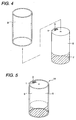
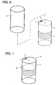
- a method of manufacturing the metallic carrier is shown in JP-A-5-131143 or Figs. 4 to 7.
- a manufacturing method is known in which a belt-shaped corrugated sheet 1 and a flat sheet 3 which are formed of metal sheets are alternately superposed one on another, and are rolled and formed into a core (honeycomb body) 5 having a circular cross-sectional shape or a cross-sectional shape of a racing track, and an Ni brazing foil material 7 is wound around an outer periphery of the rear side (exhaust gas outlet side) of the core 5 or a central portion thereof.
- This assembly is press-fitted in a metallic outer cylinder 9 and is heated (subjected to heat treatment) in a vacuum state so as to diffusionally join together the corrugated sheet 1 and the flat sheet 3 and braze together the outer cylinder 9 and the core 5, thereby manufacturing the metallic carrier 11 or 13.
- the aforementioned shape of a racing track refers to a substantially elliptical shape similar to the shape of a track in track and field and consisting of two opposing straight portions and two opposing semicircular portions connecting them.
- Prior art document JP 8 141 413 A teaches a method for manufacturing a metallic carrier for a catalytic converter as well as a metallic carrier for a catalytic converter.
- said metallic carrier is constituted by a honeycomb body formed by laying a metallic corrugated sheet over a metallic flat sheet and spirally winding them. Said honeycomb body is inserted into an outer cylinder and subjected to diffusionally joining same with a brazing material provided on said honeycomb body.
- Prior art document US 4,948,774 is directed to a metal-made carrier body for carrying thereon an exhaust gas cleaning catalyst comprising a metal casing and a multi-layered composite structure or honeycomb structure composed of a sheet-like metal band and a corrugated metal band enclosed in the metal casing and joined therewith.
- the outer metallic cylinder is provided with a plurality of so called brazing-material-holding grooves. With the brazing material accommodated within the groove and honeycomb structure inserted into the metallic cylinder, the respective assembly is subjected to a heat treatment in order to join the elements by brazing, especially at the position of said groove.
- said objective is solved by a method for manufacturing a metallic carrier for a catalytic converter having the features of independent claim 1.
- said objective is solved by a method for manufacturing a metallic carrier for a catalytic converter having the features of independent claim 2.
- a metallic carrier for a catalytic converter which is aimed at preventing falling away of core parts in cellular forms due to the rising of the solder during heat treatment
- a metallic carrier for a catalytic converter in which a brazing foil material is wound around an outer periphery of an exhaust gas outlet side of a core formed by superposing one on top another corrugated sheet and flat sheet formed of metal sheets and by rolling them, and an assembly thereof is press-fitted into a metallic outer cylinder and is subjected to heat treatment so as to diffusionally join together the corrugated sheet and the flat sheet and join together an inner periphery of the outer cylinder and an outer periphery of the core by a brazing material, characterized in that a solder-rising preventing groove is provided over an entire circumference of the inner periphery of the outer cylinder at a position located on an exhaust gas inlet side of an area for joining the core).
- a metallic carrier for a catalytic converter in which a brazing foil material is wound around an outer periphery of a central portion of a core formed by superposing one on top another corrugated sheet and flat sheet formed of a metal sheet and by rolling them, and an assembly thereof is press-fitted into a metallic outer cylinder and is subjected to heat treatment so as to diffusionally join together the corrugated sheet and the flat sheet and join together an inner periphery of the outer cylinder and an outer periphery of the core by a brazing material), characterized in that solder-rising preventing grooves are provided over an entire circumference of the inner periphery of the outer cylinder at positions located on an exhaust gas inlet side and an exhaust gas outlet side, respectively, of an area for joining the core.
- the brazing material which melted by heat treatment during its manufacture tends to rise toward the exhaust gas inlet side of the core due to the capillary phenomenon, but the brazing material holds in the solder-rising preventing groove provided in the inner periphery of the outer cylinder, thereby preventing the rising of the solder to the exhaust gas inlet side of the core.
- the brazing foil material melts and tends to flow toward the exhaust gas inlet side and the exhaust gas outlet side of the core due to the capillary phenomenon during heat treatment in its manufacturing process, but the brazing material holds in the solder-rising preventing grooves provided in the inner periphery of the outer cylinder, thereby preventing further efflux thereof, that is, preventing the melted brazing material from rising across the solder-rising preventing groove.
- Figs. 1A, 1B and 2 illustrate an embodiment of a metallic carrier according to the present teaching.
- reference numeral 15 denotes a cylindrically shaped outer cylinder formed of a ferritic stainless steel of SUS 430, and the inside diameter m of the outer cylinder 15 is made smaller than the outside diameter n of a core 5 in Fig. 4 which is press-fitted into it.
- a metallic carrier 17 in accordance with the embodiment is manufactured such that after the core 5 with a brazing foil material 7 wound around an outer periphery of its rear side is press-fitted into the outer cylinder 15, this assembly is heated in a vacuum state to diffusionally join together a corrugated sheet 1 and a flat sheet 3 and join together the inner periphery of the outer cylinder 15 and the outer periphery of the core 5 by the brazing material.
- the embodiment is characterized in that a solder-rising preventing groove 19 is provided over the entire circumference of the inner periphery of the outer cylinder 15 at a position located on the front side of the area for joining the core 5.
- the width and the depth of the solder-rising preventing groove 19 are appropriately selected in accordance with the volume of the metallic carrier to be manufactured and the volume of the brazing foil material to be used.
- the metallic carrier 17 in accordance with this embodiment is constructed as described above, as shown in Fig. 2, a brazing material 7-1 which melted by heat treatment during its manufacture tends to rise toward the front side of the core 5 due to the capillary phenomenon, but the brazing material 7-1 holds in the solder-rising preventing groove 19 provided in the inner periphery of the outer cylinder 15, thereby preventing the rising of the solder to the front side of the core 5.
- the partial joining of the outer cylinder 15 and the front side of the core 5 is prevented, with the result that falling away of core parts in cellular forms can be prevented.
- Fig. 3 illustrates another embodiment of the metallic carrier.
- reference numeral 21 denotes an outer cylinder formed of the same material as the aforementioned outer cylinder 15, and the inside diameter m of the outer cylinder 21 is also made smaller than the outside diameter of the core 5 which is press-fitted into it.
- a metallic carrier 23 in accordance with this embodiment is manufactured such that after the core 5 with the brazing foil material 7 wound around an outer periphery of its central portion is press-fitted into the outer cylinder 21, this assembly is heated in a vacuum state so as to diffusionally join together the corrugated sheet 1 and the flat sheet 3 and join together the inner periphery of the outer cylinder 21 and the outer periphery of the core 5 by the brazing material.
- this embodiment is characterized in that solder-rising preventing grooves 25 and 27 are provided over the entire circumference of the inner periphery of the outer cylinder 21 at positions located on the front side and the rear side, respectively, of the area for joining the core 5.
- the width and the depth of the solder-rising preventing groove 25 and 27 are appropriately selected in accordance with the volume of the metallic carrier to be manufactured and the volume of the brazing foil material to be used.
- the brazing foil material 7-1 melts and tends to flow toward the front side and the rear side of the core 5 due to the capillary phenomenon during heat treatment in its manufacturing process, but the brazing material 7-1 holds in the solder-rising preventing grooves 25 and 27 provided in the inner periphery of the outer cylinder 21, thereby preventing further efflux thereof.
- the partial joining of the outer cylinder 21 and the front and rear sides of the core 5 is prevented, with the result that it becomes possible to prevent falling away of core parts in cellular forms.
- the recessed solder-rising preventing grooves 19, 25, and 27 are provided in the inner periphery of the outer cylinder 15 or 21 to prevent the rising of the brazing material 7-1
- an arrangement may be alternatively provided such that after the core with the brazing foil material wound around the outer periphery of its rear side is press-fitted into the outer cylinder, a portion of the outer cylinder located on the front side of the area for joining the core is made to protrude inwardly over the entire circumference, and an outermost layer of the core is crushed, thereby preventing the rising of the brazing material during heat treatment.
- flat belt-shaped metal sheets are used as the flat sheet 3 for forming the core 5
- the flat sheet having corrugations whose ridge height is sufficiently smaller than that of the corrugated sheet 1 may be used as the flat sheet 3.
- the brazing material which melted by heat treatment during manufacture tends to rise toward the exhaust gas inlet side of the core due to the capillary phenomenon, but the brazing material holds in the solder-rising preventing groove provided in the inner periphery of the outer cylinder, thereby preventing the rising of the solder. Accordingly, the partial joining of the outer cylinder and the exhaust gas inlet side of the core is prevented, with the result that falling away of core parts in cellular forms can be prevented.
- the brazing material which melted by heat treatment during manufacture tends to flow toward the exhaust gas inlet side and the exhaust gas outlet side of the core, but the brazing material holds in the solder-rising preventing groove provided in the inner periphery of the outer cylinder, thereby preventing further efflux thereof. Accordingly, it becomes possible to prevent falling away of core parts in cellular forms.
Landscapes
- Chemical & Material Sciences (AREA)
- Chemical Kinetics & Catalysis (AREA)
- Engineering & Computer Science (AREA)
- Health & Medical Sciences (AREA)
- Toxicology (AREA)
- Combustion & Propulsion (AREA)
- Mechanical Engineering (AREA)
- General Engineering & Computer Science (AREA)
- Catalysts (AREA)
- Exhaust Gas After Treatment (AREA)
Claims (2)
- Verfahren zum Herstellen eines metallischen Trägers für einen katalytischen Wandler, das die Schritte aufweist von:- Bilden eines Kerns (5) durch Überlagern eines aus Metall hergestellten, gewellten Bleches (1) und eines aus Metall hergestellten, flachen Bleches (3), eins über dem anderen, und durch mehrfaches Rollen des gewellten Bleches (1) und des flachen Bleches (3) in mehreren Umläufen;- Aufwickeln eines Hartlot- Folienmaterials (7) rund um einen Außenumfang einer Abgasauslassseite des Kerns (5);- Vorsehen eines metallischen Außenzylinders (15), wobei ein Bereich zum Verbinden des Kerns (5) mit dem Innenumfang des metallischen Außenzylinders (15) an der Abgasauslassseite des Kerns (5) gebildet wird, und einer Lotanstiegs- Verhinderungsnut (19) über einen gesamten Umfang des Innenumfangs des Außenzylinders (15) an einer Stelle gebildet wird, die an einer Abgaseinlassseite des Bereiches zum Verbinden des Kerns (5) mit dem Innenumfang des metallischen Außenzylinders (15) angeordnet ist,- Press- einsetzen einer Anordnung, die den Kern (5) und das Hartlot- Folienmaterial (7) enthält, in den metallischen Außenzylinder (15);- Unterziehen der Anordnung, die den Kern (5) und das Hartlot- Folienmaterial (7) und den metallischen Außenzylinder (15) enthält, einer Wärmebehandlung, um das gewellte Blech (1) und das flache Blech (3) diffusionszuverbinden und Verbinden eines Innenumfangs des metallischen Außenzylinders (15) und eines Außenumfangs des Kerns (5) durch ein Hartlotmaterial, wobei- das Verbinden des Kerns (5) und des metallischen Außenzylinders (15) zwischen der Lotanstiegs- Verhinderungsnut (19) und dem Abgaseinlass des Kerns (5) durch die Lotanstiegs- Verhinderungsnut (19) verhindert wird, um den Fluss des Hartlotmaterials zwischen der Lotanstiegs- Verhinderungsnut (19) und dem Abgaseinlass des Kerns (5) zu verhindern.
- Verfahren zum Herstellen eines metallischen Trägers für einen katalytischen Wandler, das die Schritte aufweist von:- Bilden eines Kerns (5) durch Überlagern eines aus Metall hergestellten, gewellten Bleches (1) und eines aus Metall hergestellten, flachen Bleches (3), eins über dem anderen, und durch mehrfaches Rollen des gewellten Bleches (1) und des flachen Bleches (3) in mehreren Umläufen;- Aufwickeln eines Hartlot- Folienmaterials (7) rund um den Außenumfang eines mittleren Abschnittes des Kerns (5);- Vorsehen eines metallischen Außenzylinders (21), wobei ein Bereich zum Verbinden des Kerns (5) mit dem Innenumfang des metallischen Außenzylinders (21) an dem mittleren Abschnitt des Kerns (5) gebildet wird, und wobei Lotanstiegs- Verhinderungsnuten (25, 27) über einen gesamten Umfang des Innenumfangs des Außenzylinders (21) an einer Position gebildet werden, die an einer vorderen Seite und an einer hinteren Seite des Bereichs zum Verbinden des Kerns (5) mit dem Innenumfang des metallischen Außenzylinders (21) angeordnet sind,- Press- einsetzen einer Anordnung, die den Kern (5) und das Hartlot- Folienmaterial (7) enthält, in den metallischen Außenzylinder (21);- Unterziehen der Anordnung, die den Kern (5) und das Hartlot- Folienmaterial (7) und den metallischen Außenzylinder (21) enthält, einer Wärmebehandlung, um das gewellte Blech (1) und das flache Blech (3) diffusionszuverbinden und Verbinden eines Innenumfangs des metallischen Außenzylinders (21) und eines Außenumfangs des Kerns (5) durch ein Hartlotmaterial, wobei- das Verbinden des Kerns (5) und des metallischen Außenzylinders (21) zwischen der Lotanstiegs- Verhinderungsnut (25), an der vorderen Seite des Bereichs zum Verbinden und einer vorderen Seite des Kerns (5), und zwischen der Lotanstiegs- Verhinderungsnut (27), an der hinteren Seite des Bereichs zum Verbinden und einer hinteren Seite des Kerns (5) durch die Lotanstiegs- Verhinderungsnuten (25, 27) verhindert wird, um den Fluss des Hartlotmaterials zwischen den Lotanstiegs- Verhinderungsnuten (25, 27) und dem jeweils vorderen und hinteren Ende des Kerns (5) zu verhindern.
Applications Claiming Priority (2)
| Application Number | Priority Date | Filing Date | Title |
|---|---|---|---|
| JP2000017165A JP2001207837A (ja) | 2000-01-26 | 2000-01-26 | 触媒コンバータのメタル担体 |
| JP2000017165 | 2000-01-26 |
Publications (3)
| Publication Number | Publication Date |
|---|---|
| EP1120163A2 EP1120163A2 (de) | 2001-08-01 |
| EP1120163A3 EP1120163A3 (de) | 2003-08-13 |
| EP1120163B1 true EP1120163B1 (de) | 2007-04-11 |
Family
ID=18544194
Family Applications (1)
| Application Number | Title | Priority Date | Filing Date |
|---|---|---|---|
| EP01101545A Expired - Lifetime EP1120163B1 (de) | 2000-01-26 | 2001-01-24 | Herstellungsverfahren für einen Metallträger-Katalysator |
Country Status (4)
| Country | Link |
|---|---|
| US (1) | US20010009650A1 (de) |
| EP (1) | EP1120163B1 (de) |
| JP (1) | JP2001207837A (de) |
| DE (1) | DE60127736T2 (de) |
Families Citing this family (3)
| Publication number | Priority date | Publication date | Assignee | Title |
|---|---|---|---|---|
| DE10217259A1 (de) * | 2002-04-18 | 2003-11-13 | Emitec Emissionstechnologie | Katalysator-Trägerkörper mit Wellmantel und Verfahren zu dessen Herstellung |
| US7476366B2 (en) * | 2002-04-18 | 2009-01-13 | Emitec Gesellschaft Fuer Emissionstechnologie Mbh | Catalyst carrier body with corrugated casing and process for producing the same |
| CN109884256A (zh) * | 2019-03-27 | 2019-06-14 | 河南科技大学 | Scr催化箱多截面测量系统 |
Family Cites Families (4)
| Publication number | Priority date | Publication date | Assignee | Title |
|---|---|---|---|---|
| DE2856030C2 (de) * | 1978-12-23 | 1987-02-12 | Süddeutsche Kühlerfabrik Julius Fr. Behr GmbH & Co KG, 7000 Stuttgart | Verfahren zum Herstellen einer aus Metallfolien gewickelten Trägermatrix für eine Abgaspatrone |
| KR920005089B1 (ko) * | 1988-07-06 | 1992-06-26 | 우스이 고꾸사이 산교 가부시끼가이샤 | 배기가스 정화용 촉매를 담지하기 위한 금속제 담지모체(擔持母體)와 그의 제조방법 |
| KR920009120B1 (ko) * | 1988-07-06 | 1992-10-13 | 우스이 고꾸사이 산교 가부시끼가이샤 | 배기가스 정화용 촉매를 담지하기 위한 금속제 담지모체(擔持母體) |
| JP3217393B2 (ja) | 1991-07-11 | 2001-10-09 | 新日本製鐵株式会社 | メタル担体の製造方法 |
-
2000
- 2000-01-26 JP JP2000017165A patent/JP2001207837A/ja active Pending
-
2001
- 2001-01-24 DE DE60127736T patent/DE60127736T2/de not_active Expired - Fee Related
- 2001-01-24 EP EP01101545A patent/EP1120163B1/de not_active Expired - Lifetime
- 2001-01-25 US US09/768,512 patent/US20010009650A1/en not_active Abandoned
Also Published As
| Publication number | Publication date |
|---|---|
| US20010009650A1 (en) | 2001-07-26 |
| EP1120163A3 (de) | 2003-08-13 |
| DE60127736D1 (de) | 2007-05-24 |
| EP1120163A2 (de) | 2001-08-01 |
| DE60127736T2 (de) | 2007-08-16 |
| JP2001207837A (ja) | 2001-08-03 |
Similar Documents
| Publication | Publication Date | Title |
|---|---|---|
| US5110561A (en) | Exhaust gas cleaning device | |
| US5336472A (en) | Honeycomb structure for purifying exhaust gas and method of manufacturing same | |
| JP3755008B2 (ja) | 排ガス浄化用金属製触媒担体の製造方法 | |
| US5403558A (en) | Heat and fatigue resistant metallic carrier for automobile exhaust gas-purifying catalyst | |
| JPH10280949A (ja) | 内燃機関用触媒コンバータの金属触媒担体 | |
| US6821639B2 (en) | Metal substrate for carrying catalyst and method for manufacturing the same | |
| EP1120163B1 (de) | Herstellungsverfahren für einen Metallträger-Katalysator | |
| US5173471A (en) | Exhaust gas cleaning device | |
| US5153167A (en) | Honeycomb catalyst carrier | |
| EP0389645B1 (de) | Metallträger mit widerstand gegen thermische ermüdung bei abgasfahrzeugkatalysatoren | |
| CN101268261A (zh) | 具有端面硬钎焊区域的蜂窝体 | |
| US6660401B2 (en) | Disposition of solder for heat resistant structure | |
| JP4132531B2 (ja) | 触媒コンバータのメタル担体 | |
| JP2010125423A (ja) | 金属触媒担体 | |
| EP1504817B1 (de) | Metallträger für abgasreinigung | |
| JP2885830B2 (ja) | 排気ガス浄化用触媒を担持するための金属製担持母体 | |
| JP3308075B2 (ja) | 耐熱構造体の製造方法 | |
| JPH05146685A (ja) | 排気ガス浄化用触媒及びその製造方法 | |
| JP2005177736A (ja) | メタル担体 | |
| JP7780588B1 (ja) | ハニカムユニット及び触媒コンバータ | |
| JPH09267044A (ja) | 触媒装置用メタル担体 | |
| JP7254551B2 (ja) | ハニカム体、触媒担持用コンバータ及び熱交換器用ハニカム体 | |
| JP2002233771A (ja) | 触媒コンバータのメタル担体 | |
| JP2025024959A (ja) | ハニカムユニットおよび触媒コンバータ | |
| KR940006761Y1 (ko) | 배기가스 정화장치 |
Legal Events
| Date | Code | Title | Description |
|---|---|---|---|
| PUAI | Public reference made under article 153(3) epc to a published international application that has entered the european phase |
Free format text: ORIGINAL CODE: 0009012 |
|
| AK | Designated contracting states |
Kind code of ref document: A2 Designated state(s): AT BE CH CY DE DK ES FI FR GB GR IE IT LI LU MC NL PT SE TR |
|
| AX | Request for extension of the european patent |
Free format text: AL;LT;LV;MK;RO;SI |
|
| PUAL | Search report despatched |
Free format text: ORIGINAL CODE: 0009013 |
|
| AK | Designated contracting states |
Designated state(s): AT BE CH CY DE DK ES FI FR GB GR IE IT LI LU MC NL PT SE TR |
|
| AX | Request for extension of the european patent |
Extension state: AL LT LV MK RO SI |
|
| 17P | Request for examination filed |
Effective date: 20030908 |
|
| 17Q | First examination report despatched |
Effective date: 20031212 |
|
| AKX | Designation fees paid |
Designated state(s): DE FR GB |
|
| 17Q | First examination report despatched |
Effective date: 20031212 |
|
| GRAP | Despatch of communication of intention to grant a patent |
Free format text: ORIGINAL CODE: EPIDOSNIGR1 |
|
| RTI1 | Title (correction) |
Free format text: METHOD FOR MANUFACTURING A METALLIC CARRIER FOR A CATALYTIC CONVERTER |
|
| GRAS | Grant fee paid |
Free format text: ORIGINAL CODE: EPIDOSNIGR3 |
|
| GRAA | (expected) grant |
Free format text: ORIGINAL CODE: 0009210 |
|
| AK | Designated contracting states |
Kind code of ref document: B1 Designated state(s): DE FR GB |
|
| REG | Reference to a national code |
Ref country code: GB Ref legal event code: FG4D |
|
| REF | Corresponds to: |
Ref document number: 60127736 Country of ref document: DE Date of ref document: 20070524 Kind code of ref document: P |
|
| ET | Fr: translation filed | ||
| PLBE | No opposition filed within time limit |
Free format text: ORIGINAL CODE: 0009261 |
|
| STAA | Information on the status of an ep patent application or granted ep patent |
Free format text: STATUS: NO OPPOSITION FILED WITHIN TIME LIMIT |
|
| 26N | No opposition filed |
Effective date: 20080114 |
|
| PGFP | Annual fee paid to national office [announced via postgrant information from national office to epo] |
Ref country code: GB Payment date: 20080123 Year of fee payment: 8 Ref country code: DE Payment date: 20080117 Year of fee payment: 8 |
|
| PGFP | Annual fee paid to national office [announced via postgrant information from national office to epo] |
Ref country code: FR Payment date: 20080108 Year of fee payment: 8 |
|
| GBPC | Gb: european patent ceased through non-payment of renewal fee |
Effective date: 20090124 |
|
| PG25 | Lapsed in a contracting state [announced via postgrant information from national office to epo] |
Ref country code: DE Free format text: LAPSE BECAUSE OF NON-PAYMENT OF DUE FEES Effective date: 20090801 |
|
| REG | Reference to a national code |
Ref country code: FR Ref legal event code: ST Effective date: 20091030 |
|
| PG25 | Lapsed in a contracting state [announced via postgrant information from national office to epo] |
Ref country code: GB Free format text: LAPSE BECAUSE OF NON-PAYMENT OF DUE FEES Effective date: 20090124 |
|
| PG25 | Lapsed in a contracting state [announced via postgrant information from national office to epo] |
Ref country code: FR Free format text: LAPSE BECAUSE OF NON-PAYMENT OF DUE FEES Effective date: 20090202 |