EP1120180A1 - Procédé et dispositif pour la coulée continue de métaux - Google Patents
Procédé et dispositif pour la coulée continue de métaux Download PDFInfo
- Publication number
- EP1120180A1 EP1120180A1 EP01101347A EP01101347A EP1120180A1 EP 1120180 A1 EP1120180 A1 EP 1120180A1 EP 01101347 A EP01101347 A EP 01101347A EP 01101347 A EP01101347 A EP 01101347A EP 1120180 A1 EP1120180 A1 EP 1120180A1
- Authority
- EP
- European Patent Office
- Prior art keywords
- crystallizer
- tank
- liquid metal
- process according
- induction coil
- Prior art date
- Legal status (The legal status is an assumption and is not a legal conclusion. Google has not performed a legal analysis and makes no representation as to the accuracy of the status listed.)
- Granted
Links
- 238000009749 continuous casting Methods 0.000 title claims abstract description 9
- 239000002184 metal Substances 0.000 title claims description 34
- 229910052751 metal Inorganic materials 0.000 title claims description 34
- 238000000034 method Methods 0.000 title claims description 26
- 230000008569 process Effects 0.000 title claims description 23
- 150000002739 metals Chemical class 0.000 title 1
- 229910001338 liquidmetal Inorganic materials 0.000 claims abstract description 45
- 239000011819 refractory material Substances 0.000 claims abstract description 21
- 230000005291 magnetic effect Effects 0.000 claims abstract description 14
- 238000007711 solidification Methods 0.000 claims abstract description 10
- 230000008023 solidification Effects 0.000 claims abstract description 9
- 239000006228 supernatant Substances 0.000 claims abstract description 3
- 230000006698 induction Effects 0.000 claims description 25
- 239000000314 lubricant Substances 0.000 claims description 23
- 230000009471 action Effects 0.000 claims description 11
- 230000005672 electromagnetic field Effects 0.000 claims description 10
- 238000004804 winding Methods 0.000 claims description 10
- 238000009877 rendering Methods 0.000 claims description 9
- 238000005304 joining Methods 0.000 claims description 8
- 238000001816 cooling Methods 0.000 claims description 7
- 230000005294 ferromagnetic effect Effects 0.000 claims description 7
- 239000000463 material Substances 0.000 claims description 7
- 239000002245 particle Substances 0.000 claims description 6
- 238000007599 discharging Methods 0.000 claims description 5
- 230000001050 lubricating effect Effects 0.000 claims description 4
- 230000005520 electrodynamics Effects 0.000 claims description 3
- 239000000203 mixture Substances 0.000 claims description 2
- 230000035699 permeability Effects 0.000 claims description 2
- 239000011248 coating agent Substances 0.000 claims 1
- 238000000576 coating method Methods 0.000 claims 1
- 230000000295 complement effect Effects 0.000 claims 1
- 239000002826 coolant Substances 0.000 claims 1
- 230000005499 meniscus Effects 0.000 abstract description 6
- 239000000843 powder Substances 0.000 abstract description 5
- 239000000047 product Substances 0.000 description 12
- 239000007789 gas Substances 0.000 description 6
- 230000010355 oscillation Effects 0.000 description 6
- 230000015572 biosynthetic process Effects 0.000 description 5
- 238000005266 casting Methods 0.000 description 5
- 239000000243 solution Substances 0.000 description 5
- XKRFYHLGVUSROY-UHFFFAOYSA-N Argon Chemical compound [Ar] XKRFYHLGVUSROY-UHFFFAOYSA-N 0.000 description 4
- 230000004913 activation Effects 0.000 description 3
- 230000007547 defect Effects 0.000 description 3
- 238000009826 distribution Methods 0.000 description 3
- 239000010410 layer Substances 0.000 description 3
- 238000011144 upstream manufacturing Methods 0.000 description 3
- IJGRMHOSHXDMSA-UHFFFAOYSA-N Atomic nitrogen Chemical compound N#N IJGRMHOSHXDMSA-UHFFFAOYSA-N 0.000 description 2
- 229910052786 argon Inorganic materials 0.000 description 2
- 238000010586 diagram Methods 0.000 description 2
- 230000004907 flux Effects 0.000 description 2
- 238000005461 lubrication Methods 0.000 description 2
- 238000004519 manufacturing process Methods 0.000 description 2
- 230000003647 oxidation Effects 0.000 description 2
- 238000007254 oxidation reaction Methods 0.000 description 2
- 239000011241 protective layer Substances 0.000 description 2
- 229910000831 Steel Inorganic materials 0.000 description 1
- 239000007795 chemical reaction product Substances 0.000 description 1
- 239000011247 coating layer Substances 0.000 description 1
- 239000012141 concentrate Substances 0.000 description 1
- 230000001143 conditioned effect Effects 0.000 description 1
- 239000000498 cooling water Substances 0.000 description 1
- 238000006073 displacement reaction Methods 0.000 description 1
- 230000000694 effects Effects 0.000 description 1
- 238000010292 electrical insulation Methods 0.000 description 1
- 239000012777 electrically insulating material Substances 0.000 description 1
- 230000008030 elimination Effects 0.000 description 1
- 238000003379 elimination reaction Methods 0.000 description 1
- 238000005188 flotation Methods 0.000 description 1
- 239000012530 fluid Substances 0.000 description 1
- 239000012634 fragment Substances 0.000 description 1
- 230000005484 gravity Effects 0.000 description 1
- 238000010438 heat treatment Methods 0.000 description 1
- 238000002347 injection Methods 0.000 description 1
- 239000007924 injection Substances 0.000 description 1
- 238000007689 inspection Methods 0.000 description 1
- 238000009413 insulation Methods 0.000 description 1
- 230000001788 irregular Effects 0.000 description 1
- 239000013528 metallic particle Substances 0.000 description 1
- 229910052757 nitrogen Inorganic materials 0.000 description 1
- 239000003921 oil Substances 0.000 description 1
- 238000005457 optimization Methods 0.000 description 1
- 230000035515 penetration Effects 0.000 description 1
- 230000008092 positive effect Effects 0.000 description 1
- 230000001737 promoting effect Effects 0.000 description 1
- 239000007787 solid Substances 0.000 description 1
- 239000010959 steel Substances 0.000 description 1
- 238000004381 surface treatment Methods 0.000 description 1
- 230000009466 transformation Effects 0.000 description 1
- 238000011282 treatment Methods 0.000 description 1
- 238000009827 uniform distribution Methods 0.000 description 1
- XLYOFNOQVPJJNP-UHFFFAOYSA-N water Substances O XLYOFNOQVPJJNP-UHFFFAOYSA-N 0.000 description 1
- 238000003466 welding Methods 0.000 description 1
Images


Classifications
-
- B—PERFORMING OPERATIONS; TRANSPORTING
- B22—CASTING; POWDER METALLURGY
- B22D—CASTING OF METALS; CASTING OF OTHER SUBSTANCES BY THE SAME PROCESSES OR DEVICES
- B22D11/00—Continuous casting of metals, i.e. casting in indefinite lengths
- B22D11/04—Continuous casting of metals, i.e. casting in indefinite lengths into open-ended moulds
- B22D11/0401—Moulds provided with a feed head
-
- B—PERFORMING OPERATIONS; TRANSPORTING
- B22—CASTING; POWDER METALLURGY
- B22D—CASTING OF METALS; CASTING OF OTHER SUBSTANCES BY THE SAME PROCESSES OR DEVICES
- B22D11/00—Continuous casting of metals, i.e. casting in indefinite lengths
- B22D11/07—Lubricating the moulds
-
- B—PERFORMING OPERATIONS; TRANSPORTING
- B22—CASTING; POWDER METALLURGY
- B22D—CASTING OF METALS; CASTING OF OTHER SUBSTANCES BY THE SAME PROCESSES OR DEVICES
- B22D11/00—Continuous casting of metals, i.e. casting in indefinite lengths
- B22D11/10—Supplying or treating molten metal
- B22D11/11—Treating the molten metal
- B22D11/114—Treating the molten metal by using agitating or vibrating means
- B22D11/115—Treating the molten metal by using agitating or vibrating means by using magnetic fields
Definitions
- the present invention refers to a process for improving the quality of continuously cast metallic bodies and to the corresponding implementation device. More precisely, it refers to an essentially electromagnetic process and to the corresponding implementation device, which may be used in continuous-casting plants for casting billets, blooms and slabs, for improving the surface and internal quality of the cast product, when a tank made of refractory material is set upstream of the crystallizer.
- Continuous casting is a technique extensively used in the production of metallic bodies having various shapes and sizes (blooms, slabs, and billets), which has reached a high level of efficiency, both in terms of reliability of the plants and systems and in terms of quality of the products obtained, which is generally satisfactory.
- the above technique albeit interesting, poses further problems.
- the area of joining between the refractory material of the walls of the "tank" and the contiguous edge of the cooled metal crystallizer, referred to as "triple point” proves very delicate both on account of the possible desegregation of the refractory material due to the sharp thermal jump between the latter and the cooled crystallizer, and because the molten metal tends to start solidifying precisely at the said joining point, with a high likelihood of adhesion to the refractory material and corresponding problems of formation of surface defects in the bodies produced, or, worse still, of catastrophic tearing of the skin and consequent leakage of the liquid metal, which may cause damage to the casting machine and the stoppage of operations.
- the US patents Nos. 5 494 095 and 5 379 828 propose to set, between the "tank" made of refractory material and the crystallizer, an insert consisting of a material having a thermal and electrical conductivity lower than that of the material of which the crystallizer is built, so that the molten metal will start to solidify at the insert itself.
- the joint between this and the refractory material of the tank is heated by means of an alternating electromagnetic field.
- the aim of the present invention is to overcome the drawbacks discussed above, improving the surface quality of the continuously cast product, making possible a quality cast at higher speeds and hence obtaining a bigger output, by rendering the flow and the temperature of the liquid metal in the said tank uniform, preventing adhesion of the solidifying metal at the joint between the tank and the cooled crystallizer, thus reducing the depth of the markings due to oscillation in the longitudinal direction of the crystallizer and possibly getting rid of them altogether.
- the process according to the present invention uses a tank made of refractory material (set on top of a crystallizer), into which, by means of a special discharging device, liquid metal is poured continuously, the said liquid metal moving with disordered motion towards the crystallizer, and in the latter starting to solidify at a point corresponding to the joining area (i.e., the aforesaid "triple point") between the tank and the crystallizer, forming a so-called "skin" on the cast body, the skin being continuously extracted from the crystallizer, the said tank having the purpose of removing, from the area of start of solidification, the free surface of the metal, the supernatant scale and the area of molten metal having perturbed flow as a result of the continuous addition of metal.
- the aforesaid process is characterized by the combination, in a relationship of co-operation, of a first action of slowing down and rendering regular the disordered motion of the liquid metal, the said action being implemented in the tank, and of a second action of detachment of the liquid metal at the said triple point, the said detachment of the liquid metal being possibly accompanied also by the detachment of the said skin from the walls of the crystallizer.
- the said first action of slowing down and of rendering uniform the motion is achieved by electromagnetic fields which are periodically interrupted and modified in direction and intensity, the said electromagnetic fields being generated by an induction system made up of a first continuous core, set around the tank and equipped with at least four poles arranged at regular intervals all around the tank, and of windings arranged around each pole, the said poles being energised in a pre-defined order (for example, simultaneously but with different intensity and sign, as illustrated in Figure 3) for a given period of time ⁇ t, and with a time interval between two consecutive energising corresponding to 0.1-0.2 ⁇ t.
- the current value used will range, as shall be seen in what follows, from 1 kA to 200 kA. The currents are considered positive when the magnetic field generated is directed towards the liquid metal.
- the second action of detachment of the liquid metal from the triple point is achieved by means a pulsating magnetic field, which is generated by a second induction coil consisting of a plurality of turns inserted into a second magnetic core which completely surrounds the crystallizer and is generally electrically insulated from the external environment.
- the second induction coil is activated by means of a pulse current, having an intensity of between 5 kA and 200 kA, preferably between 30 kA and 200 kA, with pulses having a duration of between 50 ⁇ s and 500 ⁇ s, preferably between 100 ⁇ s and 200 ⁇ s, and a frequency of between 2 Hz and 150 Hz.
- magpetic field thus produced generates electromagnetic forces directed towards the liquid metal, which in turn cause detachment of the latter from the walls of the tank-crystallizer ensemble, thus creating a stable cavity between the surface of the liquid metal and the said walls.
- the second induction coil can be set between the tank and the crystallizer, and in this way it directly faces onto the area in which the liquid metal is contained. In this case, the second induction coil must be appropriately protected by means of cooling, or else it can be set outside the crystallizer.
- the process according to the present invention also envisages the possibility of carrying out a distribution of lubricant at the aforesaid triple point, with the purpose of favouring sliding of the skin being formed against the walls of the crystallizer.
- This distribution of lubricant may be omitted if means for favouring detachment of the solidifying skin from the crystallizer walls are used.
- Preferred means for this purpose are exciters of an electrodynamic, pneumatic, magnetostrictive, or piezoelectric type, etc., applied outside the crystallizer, with at least one on each wall, to make the crystallizer vibrate both transversally and longitudinally, in order to reduce friction between the solidified skin and the walls of the crystallizer.
- the process according to the present invention also envisages the possibility of using a lubricant with ferromagnetic properties, preferably consisting of a mixture of ferromagnetic particles, sized smaller than 100 ⁇ m, in quantities of between 5 wt% and 25 wt%, and the usual powdered oxides and/or oils of the type commonly used in continuous casting.
- a lubricant with ferromagnetic properties preferably consisting of a mixture of ferromagnetic particles, sized smaller than 100 ⁇ m, in quantities of between 5 wt% and 25 wt%, and the usual powdered oxides and/or oils of the type commonly used in continuous casting.
- the part of lubricant that is in contact with the internal walls of the tank and of the crystallizer, and possibly with the second induction coil assumes a relatively low temperature, maintaining a permeability higher than unity.
- the magnetic field produced by the second induction coil keeps the lubricant in contact with the induction coil itself, if the latter is facing towards the inside of the tank-crystallizer ensemble, and in contact with the said internal walls.
- the presence of ferromagnetic particles in the lubricant ensures that on the surface of the liquid metal in contact with the lubricant itself there are electromagnetic forces which are considerably higher, for example 80 to 100 times higher, than those obtainable in the absence of the said ferromagnetic particles.
- the device according to the present invention comprises a container 1, referred to as "tank”, made of refractory material, possibly tapered towards the bottom, for example as represented in Fig. 1, set on top of a metal crystallizer 9 which is cooled by means of a cooling system 10 of its own with forced water circulation.
- a metal crystallizer 9 which is cooled by means of a cooling system 10 of its own with forced water circulation.
- an induction coil 11 (the outer surfaces of which are coated with a deposited oxide layer having an appropriate thickness, to guarantee electrical insulation) comprising a lubricant injection system 24.
- the tapered part of the container 1 is surrounded by a magnetic core 6 equipped with four poles 4, each of which is provided with a cooled gap 8 and with a winding 5.
- the induction coil 11 is made up of a plurality of turns, which are made of a material having high electrical and thermal conductivity and are inserted in a magnetic core 16, the said induction coil 11 being equipped with water-cooling means 12 and having inside it a plurality of ducts 14, which are set on one and the same plane and are fed by means of manifolds 13 with a lubricating material which is injected by means of a positive-displacement pump system (not shown) at the joint between the container 1 and the crystallizer 9, the said crystallizer 9 carrying, at its initial part where it is in contact with the tank 1, high-permeability inserts 15 (Figs.
- the induction coil 11 is not set in contact with the liquid metal, but outside the crystallizer (electrically insulated in an appropriate way from the latter), which is in turn connected to the tank by means of a joint made, in this case, preferably, by providing the outer walls of the part of the tank in contact with the crystallizer with a generically ogival or parabolic profile, the said outer walls being set in a housing having a specular profile, which is made in the top part of the crystallizer, as represented, for instance, in Fig. 6.
- the crystallizer presents, within its walls, a system of channels 10b, for circulation of the cooling water, which may be connected to channels 10c for enabling cooling also of the induction coil 11.
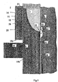
- a series of slots 28, as shown in Figure 8 is preferably made in the top part of the crystallizer in order to favour, together with the special shape of the said top part described previously, passage and concentration of the electromagnetic forces 19 at the triple point, thus enabling a cavity 23 to be obtained having satisfactory dimensions and high stability.
- Lubricant can be supplied, in this case, by way of the bottom part 14b of the said slots 28, which are filled, for the rest of their length, with refractory material, or in any case electrically insulating material.
- a further embodiment of the present invention which enables elimination of the use of lubricant, involves the use of a plurality of mechanical exciters 30, of a pneumatic, electromechanical, piezoelectric, or magnetostrictive type, etc., which are applied outside the crystallizer, as illustrated in Figure 9, at least one on each wall of the crystallizer, to induce, in the latter, vibrations in the transverse and longitudinal directions with the purpose of promoting and maintaining detachment of the solidified skin from the walls of the crystallizer, thus reducing friction between the skin and the walls.
- the frequencies of the exciters are preferably the resonance frequencies of the crystallizer-cast product system, in order to limit the power applied.
- the said frequencies generically depend upon the shape of the cast body, the geometry of the crystallizer, and the temperatures reached on the latter. To provide an indication, such frequencies may range between 100 Hz and 25000 Hz.
- coils 31 can be used, which are shown in Figure 10, each of which is equipped with a cooling system, for example an internal cooling system 32, and with an insulation system, with respect to the crystallizer 9, around which they are mounted.
- the said coils are supplied with a pulse current having an intensity of between 5 kA and 200 kA, preferably of between 30 kA and 100 kA, a pulse duration of between 50 ⁇ s and 500 ⁇ s, preferably of between 100 ⁇ s and 200 ⁇ s, and a frequency of between 2 Hz and 150 Hz, preferably of between 10 Hz and 100 Hz.
- electromagnetic forces 19b are induced on the solidified skin 20, which make it possible to detach the skin that has just formed from the walls of the crystallizer, thus reducing friction and facilitating passage of the lubricant.
- the tank 1-crystallizer 9 system which is initially closed at the bottom by a dummy bar, is filled with molten metal by means of a discharging device 3.
- the liquid metal is protected from oxidation by means of a floating layer 7 of powders and scale, or else by the creation of an inert atmosphere of argon.
- the poles 4 of the core 6 are energised in a particular order, for instance, as in Figure 3, by means of open-closed actuation of the corresponding power supplies, not shown in the Figures, in direct current for the windings 5.
- the working diagram is given in Fig.
- I A , I B , I C , I D indicate the currents in the four windings 5, which are considered positive when the magnetic field generated is directed towards the liquid metal, and ⁇ t indicates the duration of the current pulse. Two consecutive pulses are separated by a time interval corresponding to 0.1-0.2 ⁇ t.
- the molten metal 2 fed into the tank 1 by the discharging device 3 does not have a regular motion, and this causes lack of uniformity of temperature and the possibility of formation of non-metallic inclusions, such as fragments of scale or of refractory material, being drawn inside the molten bath and as far as the start-of-solidification area.
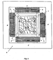
- Activation of the windings 5 with DC pulses causes the formation of magnetic fields, the flux lines of which are indicated by continuous lines, for example in Fig. 4, in the case of casting of billets/blooms. In this way, electromagnetic forces are generated according to well-known modalities, and a motion, represented by dotted lines, is thus induced in the liquid metal 2.
- the duration of each phase of activation of the windings is between 1 and 15 seconds, preferably between 4 and 10 seconds, with an interruption between two consecutive phases of a duration of between 10 and 20% of the activation time.
- the molten metal flows down in the tank, until it reaches the boundary area, or triple point.
- a further induction coil which is set between the tank 1 and the crystallizer 9, or else is set outside the said crystallizer, and is supplied by a pulse current as specified previously, generates a field of electromagnetic forces that is able to create a cavity 23 which removes the liquid metal away from the triple point, thus preventing its solidification in contact with the tank refractory walls, or in contact with the induction coil.
- a lubricant may be injected into the said cavity, which will advantageously contain ferromagnetic particles that favour concentration of the said electromagnetic forces, thus enabling the formation of a larger and more stable cavity 23.
Landscapes
- Engineering & Computer Science (AREA)
- Mechanical Engineering (AREA)
- Continuous Casting (AREA)
- Treatment Of Steel In Its Molten State (AREA)
Applications Claiming Priority (2)
| Application Number | Priority Date | Filing Date | Title |
|---|---|---|---|
| ITMI200096 | 2000-01-26 | ||
| IT2000MI000096A IT1316299B1 (it) | 2000-01-26 | 2000-01-26 | Procedimento e dispositivo per migliorare la qualita' di corpimetallici colati in continuo |
Publications (2)
| Publication Number | Publication Date |
|---|---|
| EP1120180A1 true EP1120180A1 (fr) | 2001-08-01 |
| EP1120180B1 EP1120180B1 (fr) | 2005-04-27 |
Family
ID=11443777
Family Applications (1)
| Application Number | Title | Priority Date | Filing Date |
|---|---|---|---|
| EP01101347A Revoked EP1120180B1 (fr) | 2000-01-26 | 2001-01-22 | Procédé et dispositif pour la coulée continue de métaux |
Country Status (5)
| Country | Link |
|---|---|
| US (1) | US20010017198A1 (fr) |
| EP (1) | EP1120180B1 (fr) |
| AT (1) | ATE294037T1 (fr) |
| DE (1) | DE60110273D1 (fr) |
| IT (1) | IT1316299B1 (fr) |
Cited By (2)
| Publication number | Priority date | Publication date | Assignee | Title |
|---|---|---|---|---|
| CN103464706A (zh) * | 2013-09-26 | 2013-12-25 | 上海大学 | 连续铸造制备高取向均匀细晶组织的方法及制备装置 |
| CN112496281A (zh) * | 2020-12-10 | 2021-03-16 | 东北大学 | 一种分体式电磁半连铸结晶器与应用方法 |
Families Citing this family (7)
| Publication number | Priority date | Publication date | Assignee | Title |
|---|---|---|---|---|
| CN101497114B (zh) * | 2009-03-26 | 2011-06-01 | 田志恒 | 连铸机结晶器加保护渣装置及方法 |
| CN105772664B (zh) * | 2014-12-26 | 2018-02-23 | 北京有色金属研究总院 | 一种用于电磁搅拌的气滑结晶器装置及其应用方法 |
| CN112091188B (zh) * | 2020-10-13 | 2024-07-09 | 中冶赛迪工程技术股份有限公司 | 一种多段连铸结晶器 |
| CN112687419B (zh) * | 2020-12-18 | 2022-04-12 | 岭东核电有限公司 | 乏燃料除金属井及去除乏燃料上液态金属的方法 |
| CN115971433B (zh) * | 2022-12-06 | 2024-10-22 | 湖南西鼎新材料有限公司 | 一种铝锭的液压半连续铸造机台 |
| CN120095112B (zh) * | 2025-05-12 | 2025-08-22 | 兰州铝业有限公司 | 一种安全型铝合金管的深井铸造装置 |
| CN121017488B (zh) * | 2025-10-29 | 2025-12-30 | 东北大学 | 一种复合电磁立体化分区控流装置及连铸机 |
Citations (7)
| Publication number | Priority date | Publication date | Assignee | Title |
|---|---|---|---|---|
| US3987840A (en) * | 1973-11-28 | 1976-10-26 | Institut De Recherches De La Siderurgie Francaise (Irsid) | Method and apparatus for continuously casting of metal in horizontal direction |
| US4082207A (en) * | 1975-07-04 | 1978-04-04 | Agence Nationale De Valorisation De La Recherche (Anvar) | Electromagnetic apparatus for construction of liquid metals |
| JPS57127553A (en) * | 1981-01-30 | 1982-08-07 | Sumitomo Light Metal Ind Ltd | Hot top continuous casting method for aluminum |
| FR2501550A1 (fr) * | 1981-03-11 | 1982-09-17 | Fives Cail Babcock | Procede et installation de coulee continue |
| US4450892A (en) * | 1980-07-11 | 1984-05-29 | Concast, A.G. | Method and apparatus for continuous casting of metallic strands in a closed pouring system |
| US4495982A (en) * | 1981-11-18 | 1985-01-29 | Kawasaki Jukogyo Kabushiki Kaisha | Horizontal continuous casting method |
| EP0620062A1 (fr) * | 1993-03-30 | 1994-10-19 | Sollac S.A. | Procédé de coulée continue en charge des métaux et lingotière pour sa mise en oeuvre |
-
2000
- 2000-01-26 IT IT2000MI000096A patent/IT1316299B1/it active
-
2001
- 2001-01-22 DE DE60110273T patent/DE60110273D1/de not_active Expired - Lifetime
- 2001-01-22 AT AT01101347T patent/ATE294037T1/de not_active IP Right Cessation
- 2001-01-22 EP EP01101347A patent/EP1120180B1/fr not_active Revoked
- 2001-01-25 US US09/771,001 patent/US20010017198A1/en not_active Abandoned
Patent Citations (7)
| Publication number | Priority date | Publication date | Assignee | Title |
|---|---|---|---|---|
| US3987840A (en) * | 1973-11-28 | 1976-10-26 | Institut De Recherches De La Siderurgie Francaise (Irsid) | Method and apparatus for continuously casting of metal in horizontal direction |
| US4082207A (en) * | 1975-07-04 | 1978-04-04 | Agence Nationale De Valorisation De La Recherche (Anvar) | Electromagnetic apparatus for construction of liquid metals |
| US4450892A (en) * | 1980-07-11 | 1984-05-29 | Concast, A.G. | Method and apparatus for continuous casting of metallic strands in a closed pouring system |
| JPS57127553A (en) * | 1981-01-30 | 1982-08-07 | Sumitomo Light Metal Ind Ltd | Hot top continuous casting method for aluminum |
| FR2501550A1 (fr) * | 1981-03-11 | 1982-09-17 | Fives Cail Babcock | Procede et installation de coulee continue |
| US4495982A (en) * | 1981-11-18 | 1985-01-29 | Kawasaki Jukogyo Kabushiki Kaisha | Horizontal continuous casting method |
| EP0620062A1 (fr) * | 1993-03-30 | 1994-10-19 | Sollac S.A. | Procédé de coulée continue en charge des métaux et lingotière pour sa mise en oeuvre |
Non-Patent Citations (1)
| Title |
|---|
| PATENT ABSTRACTS OF JAPAN vol. 006, no. 224 (M - 170) 9 November 1982 (1982-11-09) * |
Cited By (3)
| Publication number | Priority date | Publication date | Assignee | Title |
|---|---|---|---|---|
| CN103464706A (zh) * | 2013-09-26 | 2013-12-25 | 上海大学 | 连续铸造制备高取向均匀细晶组织的方法及制备装置 |
| CN112496281A (zh) * | 2020-12-10 | 2021-03-16 | 东北大学 | 一种分体式电磁半连铸结晶器与应用方法 |
| CN112496281B (zh) * | 2020-12-10 | 2022-03-25 | 东北大学 | 一种分体式电磁半连铸结晶器与应用方法 |
Also Published As
| Publication number | Publication date |
|---|---|
| IT1316299B1 (it) | 2003-04-10 |
| DE60110273D1 (de) | 2005-06-02 |
| ATE294037T1 (de) | 2005-05-15 |
| EP1120180B1 (fr) | 2005-04-27 |
| ITMI20000096A0 (it) | 2000-01-26 |
| ITMI20000096A1 (it) | 2001-07-26 |
| US20010017198A1 (en) | 2001-08-30 |
Similar Documents
| Publication | Publication Date | Title |
|---|---|---|
| EP1120180B1 (fr) | Procédé et dispositif pour la coulée continue de métaux | |
| EP2682201A1 (fr) | Procédé et dispositif de coulée continue d'alliages d'aluminium | |
| WO1999029452A1 (fr) | Procede et appareil de moulage de metal en fusion et pieces ainsi obtenues | |
| KR100536174B1 (ko) | 전자기장을 이용한 금속의 수직 연속 주조 방법 및 이를 위한 주조 장치 | |
| JPWO1999029452A1 (ja) | 溶融金属の鋳造方法およびその装置並びに鋳片 | |
| US6520246B2 (en) | Method and device for continuous casting of molten materials | |
| JPH09277034A (ja) | 溶融金属の連続鋳造方法 | |
| JP2003266151A (ja) | 連続鋳造装置及びその方法 | |
| JP2555768B2 (ja) | 金属の連続鋳造装置および鋳造方法 | |
| JP2008525197A (ja) | 電磁気場を利用したマグネシウムビレット又はスラブ連続鋳造装置及び製造方法 | |
| JP2611559B2 (ja) | 金属の連続鋳造装置および鋳造方法 | |
| CN119703038B (zh) | 一种板坯连铸水口电磁控流装置和方法 | |
| JP3412691B2 (ja) | 溶融金属の連続鋳造法 | |
| JP3216312B2 (ja) | 金属の連続鋳造装置 | |
| JP3887200B2 (ja) | 鋼の連続鋳造方法および装置 | |
| KR100679313B1 (ko) | 고주파 전자기장을 이용한 마그네슘 빌렛 또는 슬래브 연속주조장치 | |
| JPH01150450A (ja) | 流し込みストランドの非凝固部分の取扱い方法及び装置 | |
| JP3393712B2 (ja) | 溶融金属の連続鋳造方法 | |
| JP4830240B2 (ja) | 鋼の連続鋳造方法及び装置 | |
| JPH06142854A (ja) | 電磁力を用いる鋼の連続鋳造方法および連続鋳造用金型 | |
| JPH05277685A (ja) | 金属の連続鋳造方法および連続鋳造装置 | |
| JP2757736B2 (ja) | 金属の連続鋳造装置 | |
| WO1999021670A1 (fr) | Dispositif de moulage de metal | |
| JP3042801B2 (ja) | 電磁力を用いた鋼の連続鋳造方法 | |
| JPS58224043A (ja) | 金属薄板の連続鋳造方法 |
Legal Events
| Date | Code | Title | Description |
|---|---|---|---|
| PUAI | Public reference made under article 153(3) epc to a published international application that has entered the european phase |
Free format text: ORIGINAL CODE: 0009012 |
|
| AK | Designated contracting states |
Kind code of ref document: A1 Designated state(s): AT BE CH CY DE DK ES FI FR GB GR IE IT LI LU MC NL PT SE TR |
|
| AX | Request for extension of the european patent |
Free format text: AL;LT;LV;MK;RO;SI |
|
| 17P | Request for examination filed |
Effective date: 20020130 |
|
| AKX | Designation fees paid |
Free format text: AT BE CH CY DE DK ES FI FR GB GR IE IT LI LU MC NL PT SE TR |
|
| GRAP | Despatch of communication of intention to grant a patent |
Free format text: ORIGINAL CODE: EPIDOSNIGR1 |
|
| GRAS | Grant fee paid |
Free format text: ORIGINAL CODE: EPIDOSNIGR3 |
|
| GRAA | (expected) grant |
Free format text: ORIGINAL CODE: 0009210 |
|
| AK | Designated contracting states |
Kind code of ref document: B1 Designated state(s): AT BE CH CY DE DK ES FI FR GB GR IE IT LI LU MC NL PT SE TR |
|
| PG25 | Lapsed in a contracting state [announced via postgrant information from national office to epo] |
Ref country code: NL Free format text: LAPSE BECAUSE OF FAILURE TO SUBMIT A TRANSLATION OF THE DESCRIPTION OR TO PAY THE FEE WITHIN THE PRESCRIBED TIME-LIMIT Effective date: 20050427 Ref country code: LI Free format text: LAPSE BECAUSE OF FAILURE TO SUBMIT A TRANSLATION OF THE DESCRIPTION OR TO PAY THE FEE WITHIN THE PRESCRIBED TIME-LIMIT Effective date: 20050427 Ref country code: BE Free format text: LAPSE BECAUSE OF FAILURE TO SUBMIT A TRANSLATION OF THE DESCRIPTION OR TO PAY THE FEE WITHIN THE PRESCRIBED TIME-LIMIT Effective date: 20050427 Ref country code: CH Free format text: LAPSE BECAUSE OF FAILURE TO SUBMIT A TRANSLATION OF THE DESCRIPTION OR TO PAY THE FEE WITHIN THE PRESCRIBED TIME-LIMIT Effective date: 20050427 Ref country code: FI Free format text: LAPSE BECAUSE OF FAILURE TO SUBMIT A TRANSLATION OF THE DESCRIPTION OR TO PAY THE FEE WITHIN THE PRESCRIBED TIME-LIMIT Effective date: 20050427 Ref country code: AT Free format text: LAPSE BECAUSE OF FAILURE TO SUBMIT A TRANSLATION OF THE DESCRIPTION OR TO PAY THE FEE WITHIN THE PRESCRIBED TIME-LIMIT Effective date: 20050427 |
|
| REG | Reference to a national code |
Ref country code: GB Ref legal event code: FG4D |
|
| REG | Reference to a national code |
Ref country code: CH Ref legal event code: EP |
|
| REG | Reference to a national code |
Ref country code: IE Ref legal event code: FG4D |
|
| REF | Corresponds to: |
Ref document number: 60110273 Country of ref document: DE Date of ref document: 20050602 Kind code of ref document: P |
|
| PG25 | Lapsed in a contracting state [announced via postgrant information from national office to epo] |
Ref country code: DK Free format text: LAPSE BECAUSE OF FAILURE TO SUBMIT A TRANSLATION OF THE DESCRIPTION OR TO PAY THE FEE WITHIN THE PRESCRIBED TIME-LIMIT Effective date: 20050727 Ref country code: GR Free format text: LAPSE BECAUSE OF FAILURE TO SUBMIT A TRANSLATION OF THE DESCRIPTION OR TO PAY THE FEE WITHIN THE PRESCRIBED TIME-LIMIT Effective date: 20050727 Ref country code: SE Free format text: LAPSE BECAUSE OF FAILURE TO SUBMIT A TRANSLATION OF THE DESCRIPTION OR TO PAY THE FEE WITHIN THE PRESCRIBED TIME-LIMIT Effective date: 20050727 |
|
| PG25 | Lapsed in a contracting state [announced via postgrant information from national office to epo] |
Ref country code: DE Free format text: LAPSE BECAUSE OF FAILURE TO SUBMIT A TRANSLATION OF THE DESCRIPTION OR TO PAY THE FEE WITHIN THE PRESCRIBED TIME-LIMIT Effective date: 20050728 |
|
| PG25 | Lapsed in a contracting state [announced via postgrant information from national office to epo] |
Ref country code: ES Free format text: LAPSE BECAUSE OF FAILURE TO SUBMIT A TRANSLATION OF THE DESCRIPTION OR TO PAY THE FEE WITHIN THE PRESCRIBED TIME-LIMIT Effective date: 20050807 |
|
| PG25 | Lapsed in a contracting state [announced via postgrant information from national office to epo] |
Ref country code: PT Free format text: LAPSE BECAUSE OF FAILURE TO SUBMIT A TRANSLATION OF THE DESCRIPTION OR TO PAY THE FEE WITHIN THE PRESCRIBED TIME-LIMIT Effective date: 20051010 |
|
| REG | Reference to a national code |
Ref country code: CH Ref legal event code: PL |
|
| NLV1 | Nl: lapsed or annulled due to failure to fulfill the requirements of art. 29p and 29m of the patents act | ||
| PLBI | Opposition filed |
Free format text: ORIGINAL CODE: 0009260 |
|
| PG25 | Lapsed in a contracting state [announced via postgrant information from national office to epo] |
Ref country code: GB Free format text: LAPSE BECAUSE OF NON-PAYMENT OF DUE FEES Effective date: 20060122 |
|
| PG25 | Lapsed in a contracting state [announced via postgrant information from national office to epo] |
Ref country code: IE Free format text: LAPSE BECAUSE OF NON-PAYMENT OF DUE FEES Effective date: 20060123 |
|
| PG25 | Lapsed in a contracting state [announced via postgrant information from national office to epo] |
Ref country code: LU Free format text: LAPSE BECAUSE OF NON-PAYMENT OF DUE FEES Effective date: 20060131 Ref country code: MC Free format text: LAPSE BECAUSE OF NON-PAYMENT OF DUE FEES Effective date: 20060131 |
|
| PLAX | Notice of opposition and request to file observation + time limit sent |
Free format text: ORIGINAL CODE: EPIDOSNOBS2 |
|
| 26 | Opposition filed |
Opponent name: SMS DEMAG AG Effective date: 20060113 |
|
| EN | Fr: translation not filed | ||
| GBPC | Gb: european patent ceased through non-payment of renewal fee |
Effective date: 20060122 |
|
| REG | Reference to a national code |
Ref country code: IE Ref legal event code: MM4A |
|
| PLAB | Opposition data, opponent's data or that of the opponent's representative modified |
Free format text: ORIGINAL CODE: 0009299OPPO |
|
| RDAF | Communication despatched that patent is revoked |
Free format text: ORIGINAL CODE: EPIDOSNREV1 |
|
| R26 | Opposition filed (corrected) |
Opponent name: SMS DEMAG AG Effective date: 20060113 |
|
| PGFP | Annual fee paid to national office [announced via postgrant information from national office to epo] |
Ref country code: IT Payment date: 20070607 Year of fee payment: 7 |
|
| RDAG | Patent revoked |
Free format text: ORIGINAL CODE: 0009271 |
|
| STAA | Information on the status of an ep patent application or granted ep patent |
Free format text: STATUS: PATENT REVOKED |
|
| 27W | Patent revoked |
Effective date: 20071019 |
|
| PG25 | Lapsed in a contracting state [announced via postgrant information from national office to epo] |
Ref country code: TR Free format text: LAPSE BECAUSE OF FAILURE TO SUBMIT A TRANSLATION OF THE DESCRIPTION OR TO PAY THE FEE WITHIN THE PRESCRIBED TIME-LIMIT Effective date: 20050427 |
|
| PG25 | Lapsed in a contracting state [announced via postgrant information from national office to epo] |
Ref country code: FR Free format text: LAPSE BECAUSE OF NON-PAYMENT OF DUE FEES Effective date: 20060131 |
|
| PG25 | Lapsed in a contracting state [announced via postgrant information from national office to epo] |
Ref country code: FR Free format text: LAPSE BECAUSE OF NON-PAYMENT OF DUE FEES Effective date: 20050427 Ref country code: CY Free format text: LAPSE BECAUSE OF FAILURE TO SUBMIT A TRANSLATION OF THE DESCRIPTION OR TO PAY THE FEE WITHIN THE PRESCRIBED TIME-LIMIT Effective date: 20050427 |