EP1120197A2 - Meule abrasive vitrifiée comprenant des pores partiellement remplis de résine et son procédé de fabrication - Google Patents
Meule abrasive vitrifiée comprenant des pores partiellement remplis de résine et son procédé de fabrication Download PDFInfo
- Publication number
- EP1120197A2 EP1120197A2 EP01101716A EP01101716A EP1120197A2 EP 1120197 A2 EP1120197 A2 EP 1120197A2 EP 01101716 A EP01101716 A EP 01101716A EP 01101716 A EP01101716 A EP 01101716A EP 1120197 A2 EP1120197 A2 EP 1120197A2
- Authority
- EP
- European Patent Office
- Prior art keywords
- vitrified
- resin
- abrasive
- grindstone
- abrasive grains
- Prior art date
- Legal status (The legal status is an assumption and is not a legal conclusion. Google has not performed a legal analysis and makes no representation as to the accuracy of the status listed.)
- Withdrawn
Links
- 229920005989 resin Polymers 0.000 title claims abstract description 110
- 239000011347 resin Substances 0.000 title claims abstract description 110
- 239000011148 porous material Substances 0.000 title claims abstract description 74
- 238000004519 manufacturing process Methods 0.000 title claims description 23
- 239000006061 abrasive grain Substances 0.000 claims abstract description 88
- 239000007767 bonding agent Substances 0.000 claims abstract description 37
- 239000000203 mixture Substances 0.000 claims description 64
- 239000007788 liquid Substances 0.000 claims description 60
- 239000005011 phenolic resin Substances 0.000 claims description 35
- 239000003085 diluting agent Substances 0.000 claims description 31
- 238000000034 method Methods 0.000 claims description 16
- 229920003002 synthetic resin Polymers 0.000 claims description 6
- 239000000057 synthetic resin Substances 0.000 claims description 6
- 229910003460 diamond Inorganic materials 0.000 claims description 5
- 239000010432 diamond Substances 0.000 claims description 5
- 239000003822 epoxy resin Substances 0.000 claims description 5
- 229920000647 polyepoxide Polymers 0.000 claims description 5
- 229920001187 thermosetting polymer Polymers 0.000 claims description 4
- 238000000227 grinding Methods 0.000 description 76
- XPFVYQJUAUNWIW-UHFFFAOYSA-N furfuryl alcohol Chemical compound OCC1=CC=CO1 XPFVYQJUAUNWIW-UHFFFAOYSA-N 0.000 description 51
- 239000010410 layer Substances 0.000 description 27
- 230000000052 comparative effect Effects 0.000 description 26
- 238000005470 impregnation Methods 0.000 description 10
- 239000002923 metal particle Substances 0.000 description 10
- 238000002156 mixing Methods 0.000 description 10
- 239000003795 chemical substances by application Substances 0.000 description 9
- ISWSIDIOOBJBQZ-UHFFFAOYSA-N Phenol Chemical compound OC1=CC=CC=C1 ISWSIDIOOBJBQZ-UHFFFAOYSA-N 0.000 description 7
- 239000000654 additive Substances 0.000 description 7
- 230000000996 additive effect Effects 0.000 description 6
- 239000012530 fluid Substances 0.000 description 6
- 238000010304 firing Methods 0.000 description 5
- 230000004927 fusion Effects 0.000 description 5
- 229910010271 silicon carbide Inorganic materials 0.000 description 5
- PZNSFCLAULLKQX-UHFFFAOYSA-N Boron nitride Chemical compound N#B PZNSFCLAULLKQX-UHFFFAOYSA-N 0.000 description 4
- 239000011521 glass Substances 0.000 description 4
- HBMJWWWQQXIZIP-UHFFFAOYSA-N silicon carbide Chemical compound [Si+]#[C-] HBMJWWWQQXIZIP-UHFFFAOYSA-N 0.000 description 4
- 230000003746 surface roughness Effects 0.000 description 4
- LFQSCWFLJHTTHZ-UHFFFAOYSA-N Ethanol Chemical compound CCO LFQSCWFLJHTTHZ-UHFFFAOYSA-N 0.000 description 3
- OKKJLVBELUTLKV-UHFFFAOYSA-N Methanol Chemical compound OC OKKJLVBELUTLKV-UHFFFAOYSA-N 0.000 description 3
- 239000000853 adhesive Substances 0.000 description 3
- 230000001070 adhesive effect Effects 0.000 description 3
- PNEYBMLMFCGWSK-UHFFFAOYSA-N aluminium oxide Inorganic materials [O-2].[O-2].[O-2].[Al+3].[Al+3] PNEYBMLMFCGWSK-UHFFFAOYSA-N 0.000 description 3
- 238000007731 hot pressing Methods 0.000 description 3
- 239000002245 particle Substances 0.000 description 3
- 230000008569 process Effects 0.000 description 3
- 230000009467 reduction Effects 0.000 description 3
- 229910052582 BN Inorganic materials 0.000 description 2
- 229920003261 Durez Polymers 0.000 description 2
- 239000011230 binding agent Substances 0.000 description 2
- 238000009835 boiling Methods 0.000 description 2
- 239000005388 borosilicate glass Substances 0.000 description 2
- 230000008859 change Effects 0.000 description 2
- 239000007795 chemical reaction product Substances 0.000 description 2
- 238000007796 conventional method Methods 0.000 description 2
- 239000013078 crystal Substances 0.000 description 2
- 230000000694 effects Effects 0.000 description 2
- 238000002474 experimental method Methods 0.000 description 2
- 230000006872 improvement Effects 0.000 description 2
- 239000004850 liquid epoxy resins (LERs) Substances 0.000 description 2
- 239000000463 material Substances 0.000 description 2
- 239000002244 precipitate Substances 0.000 description 2
- 239000002243 precursor Substances 0.000 description 2
- 239000002904 solvent Substances 0.000 description 2
- 239000000126 substance Substances 0.000 description 2
- 229910052844 willemite Inorganic materials 0.000 description 2
- OKTJSMMVPCPJKN-UHFFFAOYSA-N Carbon Chemical compound [C] OKTJSMMVPCPJKN-UHFFFAOYSA-N 0.000 description 1
- 239000004375 Dextrin Substances 0.000 description 1
- 229920001353 Dextrin Polymers 0.000 description 1
- 239000004372 Polyvinyl alcohol Substances 0.000 description 1
- 229910000831 Steel Inorganic materials 0.000 description 1
- IISBACLAFKSPIT-UHFFFAOYSA-N bisphenol A Chemical compound C=1C=C(O)C=CC=1C(C)(C)C1=CC=C(O)C=C1 IISBACLAFKSPIT-UHFFFAOYSA-N 0.000 description 1
- 229910052799 carbon Inorganic materials 0.000 description 1
- 239000000919 ceramic Substances 0.000 description 1
- 230000008602 contraction Effects 0.000 description 1
- 238000005336 cracking Methods 0.000 description 1
- 238000005520 cutting process Methods 0.000 description 1
- 230000002542 deteriorative effect Effects 0.000 description 1
- 235000019425 dextrin Nutrition 0.000 description 1
- 238000010586 diagram Methods 0.000 description 1
- 238000007865 diluting Methods 0.000 description 1
- KZHJGOXRZJKJNY-UHFFFAOYSA-N dioxosilane;oxo(oxoalumanyloxy)alumane Chemical compound O=[Si]=O.O=[Si]=O.O=[Al]O[Al]=O.O=[Al]O[Al]=O.O=[Al]O[Al]=O KZHJGOXRZJKJNY-UHFFFAOYSA-N 0.000 description 1
- 230000008030 elimination Effects 0.000 description 1
- 238000003379 elimination reaction Methods 0.000 description 1
- 239000000839 emulsion Substances 0.000 description 1
- 239000004744 fabric Substances 0.000 description 1
- 238000002309 gasification Methods 0.000 description 1
- 239000002184 metal Substances 0.000 description 1
- 239000007769 metal material Substances 0.000 description 1
- 238000012986 modification Methods 0.000 description 1
- 230000004048 modification Effects 0.000 description 1
- 229910052863 mullite Inorganic materials 0.000 description 1
- 230000002093 peripheral effect Effects 0.000 description 1
- 229920006122 polyamide resin Polymers 0.000 description 1
- 229920002451 polyvinyl alcohol Polymers 0.000 description 1
- 238000004904 shortening Methods 0.000 description 1
- 239000002356 single layer Substances 0.000 description 1
- 239000007787 solid Substances 0.000 description 1
- 239000010959 steel Substances 0.000 description 1
- 238000003756 stirring Methods 0.000 description 1
- 239000004575 stone Substances 0.000 description 1
- 229920001169 thermoplastic Polymers 0.000 description 1
- 229920002803 thermoplastic polyurethane Polymers 0.000 description 1
- 229920005992 thermoplastic resin Polymers 0.000 description 1
- 239000004416 thermosoftening plastic Substances 0.000 description 1
- XLYOFNOQVPJJNP-UHFFFAOYSA-N water Substances O XLYOFNOQVPJJNP-UHFFFAOYSA-N 0.000 description 1
Images

Classifications
-
- B—PERFORMING OPERATIONS; TRANSPORTING
- B24—GRINDING; POLISHING
- B24B—MACHINES, DEVICES, OR PROCESSES FOR GRINDING OR POLISHING; DRESSING OR CONDITIONING OF ABRADING SURFACES; FEEDING OF GRINDING, POLISHING, OR LAPPING AGENTS
- B24B5/00—Machines or devices designed for grinding surfaces of revolution on work, including those which also grind adjacent plane surfaces; Accessories therefor
- B24B5/02—Machines or devices designed for grinding surfaces of revolution on work, including those which also grind adjacent plane surfaces; Accessories therefor involving centres or chucks for holding work
-
- B—PERFORMING OPERATIONS; TRANSPORTING
- B24—GRINDING; POLISHING
- B24D—TOOLS FOR GRINDING, BUFFING OR SHARPENING
- B24D18/00—Manufacture of grinding tools or other grinding devices, e.g. wheels, not otherwise provided for
- B24D18/0027—Manufacture of grinding tools or other grinding devices, e.g. wheels, not otherwise provided for by impregnation
-
- B—PERFORMING OPERATIONS; TRANSPORTING
- B24—GRINDING; POLISHING
- B24D—TOOLS FOR GRINDING, BUFFING OR SHARPENING
- B24D3/00—Physical features of abrasive bodies, or sheets, e.g. abrasive surfaces of special nature; Abrasive bodies or sheets characterised by their constituents
- B24D3/02—Physical features of abrasive bodies, or sheets, e.g. abrasive surfaces of special nature; Abrasive bodies or sheets characterised by their constituents the constituent being used as bonding agent
- B24D3/04—Physical features of abrasive bodies, or sheets, e.g. abrasive surfaces of special nature; Abrasive bodies or sheets characterised by their constituents the constituent being used as bonding agent and being essentially inorganic
- B24D3/14—Physical features of abrasive bodies, or sheets, e.g. abrasive surfaces of special nature; Abrasive bodies or sheets characterised by their constituents the constituent being used as bonding agent and being essentially inorganic ceramic, i.e. vitrified bondings
- B24D3/18—Physical features of abrasive bodies, or sheets, e.g. abrasive surfaces of special nature; Abrasive bodies or sheets characterised by their constituents the constituent being used as bonding agent and being essentially inorganic ceramic, i.e. vitrified bondings for porous or cellular structure
-
- B—PERFORMING OPERATIONS; TRANSPORTING
- B24—GRINDING; POLISHING
- B24D—TOOLS FOR GRINDING, BUFFING OR SHARPENING
- B24D3/00—Physical features of abrasive bodies, or sheets, e.g. abrasive surfaces of special nature; Abrasive bodies or sheets characterised by their constituents
- B24D3/34—Physical features of abrasive bodies, or sheets, e.g. abrasive surfaces of special nature; Abrasive bodies or sheets characterised by their constituents characterised by additives enhancing special physical properties, e.g. wear resistance, electric conductivity, self-cleaning properties
- B24D3/348—Physical features of abrasive bodies, or sheets, e.g. abrasive surfaces of special nature; Abrasive bodies or sheets characterised by their constituents characterised by additives enhancing special physical properties, e.g. wear resistance, electric conductivity, self-cleaning properties utilised as impregnating agent for porous abrasive bodies
Definitions
- the present invention relates in general to a vitrified grindstone which has a vitrified abrasive structure impregnated with a cured resin, and a method of manufacturing such a vitrified grindstone.
- vitrified grindstone having a vitrified abrasive structure, in which abrasive grains and an optionally used aggregate are held together by a glassy inorganic vitrified bonding agent, and in which a multiplicity of pores or voids are formed between the abrasive grains.
- the vitrified grindstone is widely used for precision grinding operations.
- vitrified grindstone wherein the proportion or content of the inorganic bonding agent is made relatively high for increasing a grade of the vitrified grindstone and also a degree of strength with which the inorganic bonding agent holds the abrasive grains together.
- This vitrified grindstone has a relative high hardness, and can meet, to some extent, the above-indicated need for improving the grinding efficiency.
- this vitrified grindstone is not completely satisfactory.
- the use of the inorganic bonding agent in a relatively large proportion assures an increase in the strength of the vitrified grindstone, which contributes to an improvement in the grinding efficiency, but considerably reduces the porosity of the vitrified abrasive structure and results in difficult or insufficient fracturing and removal of the abrasive grains, leading to relatively easy glazing or clogging of the surface of the vitrified grindstone, relatively easy chipping of the abrasive structure, relatively difficult dressing operation of the vitrified grindstone, and other drawbacks encountered during use of the vitrified grindstone as a grinding tool.
- the use of the inorganic bonding agent in the relatively large proportion is likely to cause various drawbacks during the manufacture of the vitrified grindstone, such as cracking or deformation of the grindstone and insufficient removal or burn-out of the primary binder of the inorganic bonding agent, in the firing process.
- the insufficient removal of the binder may cause the manufactured vitrified grindstone to have some amount of residual carbon.
- Such a vitrified grindstone with reduced porosity may be manufactured by hot-pressing of the materials of the grindstone, and may be used for performing a highly efficient grinding operation.
- this manner of manufacturing the vitrified grindstone requires special manufacturing equipment which usually suffers from low manufacturing efficiency, leading to a relatively high cost of manufacture of the vitrified grindstone, and a considerable limitation in the range of size of the vitrified grindstone that can be manufactured.
- the first object may be achieved according to a first aspect of this invention, which provides a vitrified grindstone having a vitrified abrasive structure which has pores and which includes abrasive grains and an inorganic bonding agent that holds the abrasive grains together, wherein 10-95% of a total volume of the pores is filled with a cured resin.
- a suitable volumetric percentage of the total volume of the pores or voids is filled with the cured resin, so as to prevent filling of the pores with metal particles which are removed from the workpiece during a grinding operation using the present vitrified grindstone and which would otherwise be fused in the pores, causing clogging or glazing on the grinding surface of the vitrified grindstone.
- the surface of the vitrified grindstone is comparatively recessed at local spots corresponding to the resin-filled pores, during the grinding operation on the workpiece, so that the abrasive grains adjacent to the surface of the abrasive structure gradually fracture or break down and are removed, making it possible to prevent an excessive rise of the temperature on the workpiece surface due to an excessive amount of heat of friction which would be generated between the workpiece surface and the abrasive grains that remain dull, and also prevent chipping of the vitrified grindstone while permitting easy dressing of the vitrified grindstone.
- the abrasive grains which are only loosely held together by the inorganic bonding agent can be tightly held together with an additional bonding force provided by the cured resin, so that the cured resin functions to avoid early removal of those abrasive grains, assuring a high grinding ratio.
- the arrangement in which 10-95% of the total volume of the pores is filled with the cured resin is effective to prevent the hardness of the grindstone from being excessively hardened by the impregnation of the vitrified abrasive structure with the cured resin, while assuring a high grinding ratio. Since an excessive increase in the hardness of the vitrified grindstone is prevented, the present vitrified grindstone can be easily dressed as needed, making it possible to prevent a reduction in the service life of the vitrified grindstone. If the volumetric percentage of the pores that is filled with the cured resin is smaller than 10%, the effect of the impregnation of the abrasive structure with the cured resin cannot be expected. If the volumetric percentage of the pores that is filled with the cured resin is larger than 95%, the vitrified grindstone is excessively hardened, making it difficult to dress the vitrified grindstone.
- vitrified abrasive structure of the vitrified grindstone may further include an aggregate such that the abrasive grains and the aggregate are held together by the inorganic bonding agent.
- the vitrified grindstone of this first preferred form 40-90% of the total volume of the pores is filled with the cured resin.
- an excessive increase in the hardness of the vitrified grindstone is more reliably prevented owing to the arrangement in which at least 10% of the total volume of the pores remains unfilled with the cured resin.
- at least 40% of the total volume of the pores is filled with the cured resin, it is possible to more reliably prevent the conventionally encountered drawbacks such as easy filling of the pores with metal particles, easy glazing or clogging of the surface of the vitrified grindstone, easy chipping of the abrasive structure, and easy removable of the abrasive grains.
- the present vitrified grindstone can be easily dressed without having to increase a load applied to the vitrified grindstone, leading to a further increased grinding ratio and providing a further improved surface smoothness of the workpiece.
- the cured resin consists of at least one thermosetting synthetic resin which is selected from a phenol resin and an epoxy resin, so that the vitrified grindstone has a higher degree of hardness than where the resin consists of a thermoplastic resin.
- the abrasive grains includes super abrasive grains (considerably fine abrasive grains) consisting of diamond abrasive grains, CBN abrasive grains, or mixture of diamond and CBN abrasive grains.
- the super abrasive grains preferably have Knoop hardness of at least 3000. It is preferable that the super abrasive grains have an average particle size of 20-220 ⁇ m. The particle sizes of 20 ⁇ m and 220 ⁇ m correspond to 800 and 60 meshes, respectively.
- the super abrasive grains in the vitrified abrasive structure has a concentration of larger than 10 and smaller than 230, more preferably, a concentration ranging from 20 to 200.
- the vitrified abrasive structure has a porosity of 20-75% by volume, more preferably, 30-65% by volume, before the vitrified abrasive structure is impregnated with the resin.
- the inorganic bonding agent consists of a borosilicate glass or a crystallized glass which is suitable for holding super abrasive grains together.
- the crystallized glass may be, for example, a glass in which willemite precipitates.
- the inorganic bonding agent preferably has a thermal expansion coefficient ranging from ⁇ -(2 ⁇ 10 -6 ) to ⁇ +(2 ⁇ 10 -6 ) [1/K,] (where ⁇ represents a thermal expansion coefficient of the super abrasive grains), so that the super abrasive grains can be tightly bonded together by the inorganic bonding agent.
- the vitrified abrasive structure includes 15-35% by volume of the inorganic bonding agent, so that the porosity of the vitrified abrasive structure is held in the volumetric range as described above, without deteriorating the holding strength with which the bonding agent holds the abrasive grains together.
- the vitrified abrasive structure may include, as an aggregate, a pore forming agent such as an inorganic balooning agent or other inorganic hollow substance.
- the second object may be achieved according to a second aspect of this invention, which provides a method of manufacturing a vitrified grindstone having a vitrified abrasive structure which includes abrasive grains and an inorganic bonding agent that holds the abrasive grains together.
- This method comprises (a) a step of preparing a mixture of a liquid resin and a liquid diluent which is other than the liquid resin and which dilutes the liquid resin, such that the mixture includes 10-95% by volume of the liquid resin; (b) a step of impregnating the vitrified abrasive structure with the mixture; and (c) a step of curing the liquid resin contained in the mixture with which the vitrified abrasive structure is impregnated.
- the vitrified abrasive structure is impregnated with the mixture of the resin and the liquid diluent in the impregnating step, and the resin contained in the mixture is then cured or hardened in the curing step, for thereby making it possible to obtain the vitrified grindstone having the vitrified abrasive structure whose pores are partially filled with the cured resin, wherein a volume ratio of the cured resin to the pores is determined depending upon a kind of the liquid diluent and a mixing ratio of the liquid resin to the liquid diluent.
- the mixture includes 10-95% by volume of the liquid resin, 10-95% of a total volume of the pores is filled with a cured resin, as a result of the impregnation of the vitrified abrasive structure with the mixture.
- a suitable percentage of the total volume of the pores or voids of the vitrified abrasive structure is filled with the cured resin, so as to prevent filling of the pores with metal particles which are removed from the workpiece during a grinding operation using the present vitrified grindstone and which would otherwise be fused in the pores, causing clogging or glazing on the grinding surface of the vitrified grindstone.
- the surface of the vitrified grindstone is comparatively recessed at local spots corresponding to the resin-filled pores, during the grinding operation on the workpiece, so that the abrasive grains adjacent to the surface of the abrasive structure gradually fracture or break down and are removed, making it possible to prevent an excessive rise of the temperature on the workpiece surface due to an excessive amount of heat of friction which would be generated between the workpiece surface and the abrasive grains that remain dull, and also prevent chipping of the vitrified grindstone while permitting easy dressing of the vitrified grindstone.
- the abrasive grains which are only loosely held together by the inorganic bonding agent can be tightly held together with an additional bonding force provided by the cured resin, so that the cured resin functions to avoid early removal of those abrasive grains, assuring a high grinding ratio.
- the present method merely requires, in addition to the steps performed in the conventional method of manufacturing the vitrified grindstone, the impregnating step and the curing step, and does not require conventionally used special equipment such as hot pressing equipment, which usually suffers from low manufacturing efficiency and a limitation in the range of size of the vitrified grindstone that can be manufactured.
- the volume ratio of the cured resin to the pores which ratio is held in a range of 10-95%, is effective to prevent the hardness of the grindstone from being excessively hardened due to the impregnation of the vitrified abrasive structure with the cured resin, while assuring a high grinding ratio.
- the vitrified grindstone can be easily dressed as needed, making it possible to prevent a reduction in the service life of the vitrified grindstone. If the above-described volume ratio is smaller than 10%, the effect of the impregnation of the abrasive structure with the cured resin cannot be expected. If the volume ratio is larger than 95%, the vitrified grindstone is excessively hardened, making it difficult to dress the vitrified grindstone.
- the hardness of the vitrified grindstone manufactured according to this method is determined depending upon the volumetric percentage of the pores filled with the cured resin, it is possible to manufacture vitrified grindstones having respective grades different from each other, by impregnating vitrified abrasive structures identical in grade with each other, with respective mixtures having different mixing ratios of the liquid resin to the liquid diluent. Further, since the pores of the vitrified abrasive structures are not fully filled with the resin, the hardness of the vitrified grindstone can be changed even after the manufacture of the grindstone has been completed, for example, by additionally impregnating the grindstone with a suitable amount of the liquid resin. It is accordingly unnecessary to manufacture, as end products, vitrified grindstones having different grades for respective different applications, and it is possible to suitably change the grade of each of vitrified grindstones which have been prepared in the same manner to have the same grade.
- the mixture prepared in the mixture preparing step includes 40-90% by volume of the liquid resin, so that 40-90% of the total volume of the pores is filled with the cured resin. Since at least 10% of the total volume of the pores remains unfilled with the cured resin, an excessive increase in the hardness of the vitrified grindstone is more reliably prevented. Since at least 40% of the total volume of the pores is filled with the cured resin, it is possible to more reliably prevent the conventionally encountered drawbacks such as easy filling of the pores with metal particles, easy glazing or clogging of the surface of the vitrified grindstone, easy chipping of the abrasive structure, and easy removable of the abrasive grains. Thus, the vitrified grindstone can be easily dressed without having to increase a load applied to the vitrified grindstone, leading to a further increased grinding ratio and providing a further improved surface smoothness of the workpiece.
- the liquid diluent is a volatile liquid, so that the liquid diluent contained in the mixture is rapidly volatilized before the curing of the resin in the curing step.
- the vitrified abrasive structure of the vitrified grindstone is effectively reinforced by the impregnation of the vitrified abrasive structure with the resin, since the resin is cured more efficiently than where the liquid diluent is volatized during the curing of the resin or after the curing of the resin.
- the liquid diluent is volatilized at a temperature of 40-100°C, so that the liquid diluent in the mixture is not substantially volatilized at a normal temperature, and is rapidly volatilized at a relatively low temperature in the curing step before the resin is cured. Since the liquid diluent is not substantially volatilized at a normal temperature, each step of the method is easily implemented.
- Fig.1 shows an abrasive segment 10 as a vitrified grindstone constructed according to one embodiment of this invention, which grindstone has a vitrified abrasive structure reinforced by impregnation thereof with a resin.
- the abrasive segment 10 consists of a plate member which is curved so as to have a generally arcuate shape.
- Fig. 2 shows a grinding wheel 18 consisting of an inner core 12, and a circular array of abrasive segments 10 which are bonded to the outer circumferential surface of the inner core 12 with a suitable bonding adhesive such as an epoxy resin adhesive such that there does not exist any gap or clearance between the adjacent abrasive segments 10.
- the inner core 12 is formed of a metallic material, a fiber-reinforced synthetic resin or a vitrified grindstone.
- the inner core 12 has in its center a mounting through-hole 19, into which a rotary shaft of a grinding machine is to be fitted.
- Each abrasive segment 10 consists of a radially outer layer 14 having an outer grinding surface, and a radially inner layer 16 which is formed integrally with the outer layer 14 and which functions as a base support layer for mechanically supporting the outer layer 14.
- Each of the outer and inner layers 14, 16 consists of abrasive grains and an inorganic bonding agent or a vitrified bond by which the abrasive grains are held together.
- the outer and inner layers 14, 16 use the same kind of inorganic bonding agent, but use different kinds of abrasive grains.
- the outer layer 14 includes super abrasive grains, such as cubic-crystal boron nitride (CBN) or diamond abrasive grains, which have a Knoop hardness value of at least 3000, while the inner layer 16 includes ordinary ceramic abrasive grains such as fused alumina grains, silicon carbide grains or mullite grains, which are relatively inexpensive.
- the super abrasive grains used for the outer layer 14 have an average particle size within a range of 0.5-250 ⁇ m. The lower and upper limits of 0.5 ⁇ m and 250 ⁇ m respectively correspond to 32000 and 60 meshes.
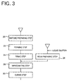
- Each of the abrasive segments 10 used for the grinding wheel 18 may be manufactured by a method illustrated in the block diagram of Fig. 3. Initially, a mixture preparing step 20 is implemented to prepare mixtures or compositions for the radially outer and inner layers 14, 16 of the abrasive segment 10. Each of the mixtures for the outer and inner layers 14, 16 includes abrasive grains, a glassy inorganic bonding agent, a caking additive such as dextrin, and optionally suitable additives such as an organic substance and an inorganic balooning agent or other pore forming agent. Desired proportions of these materials are weighed and well mixed under stirring to prepare the mixture for each of the outer and inner layers 14, 16.
- the inorganic bonding agent consists of a borosilicate glass, or a crystallized glass in which willemite precipitates.
- the inorganic bonding agent preferably has a thermal expansion coefficient ranging from ⁇ -(2 ⁇ 10 -6 ) to ⁇ +(2 ⁇ 10 -6 ) [1/K] (where ⁇ represents a thermal expansion coefficient of the super abrasive grains), at a temperature ranging from a room temperature to 500°C.
- the proportion of the inorganic bonding agent is determined such that the fired vitrified abrasive structure of the abrasive segment 10 includes 15-35% by volume of the inorganic bonding agent.
- the mixture for the outer layer 14 is prepared by mixing 18.0 parts by volume of a vitrified boding agent and 10.0 parts by volume of a caking additive into 50.0 parts by volume of CBN abrasive grains (type-I #80/#100 available form GE company), while the mixture for the inner layer 16 is prepared by mixing 18.0 parts by volume of a vitrified bonding agent and 10.0 parts by volume of a caking additive into 50.0 parts by volume of silicon carbide abrasive grains (#80).
- the mixture preparing step 20 is followed by a forming step 22 in which the prepared mixtures for the outer and inner layers 14, 16 are introduced into a suitable metal mold whose cavity has a shape following the abrasive segment 10 to be manufactured.
- the mixtures in the mold are compressed or compacted by a press, to form an unfired or green precursor for the abrasive segment 10.
- a firing step 24 is implemented to fire or burn the unfired precursor at a temperature of about 900°C, so as to obtain the fired abrasive segment 10 having, for example, a length of 40 mm, a width of 10.4 mm and a thickness of 7.4 mm.
- the caking additive included in the compositions is burnt out, while the inorganic bonding agent is fused to bond the abrasive grains together, so that the abrasive segment 10 has a porous vitrified abrasive structure having a network of continuous pores or voids, wherein the abrasive grains are held together by the inorganic bonding agent.
- the abrasive grains have a concentration of 10-230, preferably, 20-200.
- the vitrified abrasive structure has a porosity of 20-75% by volume, preferably, 30-65% by volume.
- a resin preparing step 26 is implemented to prepare a mixture by mixing a liquid phenol resin into a liquid diluent which is other than the liquid phenol resin and which does not impede curing of the resin.
- the liquid diluent preferably consists of a solvent, which is not easily volatilized at a normal temperature but is easily volatilized in a dried ambient when the resin is cured, and which has a relatively low boiling point, for example, about 200°C or lower.
- furfuryl alcohol having a boiling point of about 170°C is preferably used as the liquid diluent to be mixed into the liquid phenol resin.
- 5-95 parts by volume of the furfuryl alcohol is mixed into predetermined parts by volume of the liquid phenol resin in the form of, for example, PR-9400 (available from Sumitomo Durez Company, Ltd), such that the sum of the volumes of the furfuryl alcohol and the liquid phenol resin corresponds to 100 parts by volume.
- the furfuryl alcohol and the liquid phenol resin are stirred for about three minutes, for thereby obtaining the mixture having a relatively low viscosity.
- the fired vitrified abrasive structure of the abrasive segment 10 which has the network of the multiple continuous pores is impregnated with the mixture obtained in the resin preparing step 26, so that the liquid phenol resin (thermosetting synthetic resin) and the liquid diluent (furfuryl alcohol) contained in the mixture are dispersed evenly into the entirety of the porous vitrified abrasive structure.
- This impregnating step 28 may be performed by: pouring the mixture in the fluid or liquid state in a suitable container made of stainless such that the mass of the fluid or liquid mixture in the container has a depth of about 10mm; immersing the entirety of the abrasive segment 10 (which has been formed and fired in the forming and firing steps 22, 24) in the mass of the mixture; and evacuating the abrasive segment 10 so that the network of the continuous pores is filled with the mixture whose major component is the phenol resin.
- a selected portion of the abrasive segment 10 may be immersed in the mass of the fluid or liquid mixture.
- the impregnating step 28 is followed by a curing step 30 of holding the resin-impregnated abrasive segment 10 in a suitable drier, at a suitable temperature for a suitable length of time, for instance, at 18°C for two hours.
- This curing step 30 may be implemented after the liquid mixture which sticks to the surface of the abrasive segment 10 without permeating into the abrasive segment 10, is removed by a suitable cloth.
- the phenol resin which is contained in the mixture filling the pores is cured, while the liquid diluent (furfuryl alcohol) contained in the mixture is rapidly volatilized as the temperature rises to a volatilization point of the furfuryl alcohol at the initial stage of the process of the curing of the resin.
- the abrasive segments 10, each of which is manufactured according to the method as described above, are bonded to the outer circumferential surface of the inner core 12 having an outside diameter of ⁇ 366 mm, with an epoxy resin adhesive, so that the grinding wheel 18 as shown in Fig. 2 is formed.
- each of the abrasive segments 10 of the grinding wheel 18 a suitable percentage of the total volume of the pores or voids is filled with the cured phenol resin, so as to prevent filling of the pores with metal particles which are removed from the workpiece during a grinding operation using the grinding wheel 18 and which would otherwise be fused in the pores, causing clogging or glazing on the grinding surface of each abrasive segment 10.
- the surface of the abrasive segment 10 is comparatively recessed at local spots corresponding to the resin-filled pores, during the grinding operation on the workpiece, so that the abrasive grains adjacent to the surface of the abrasive segment 10 gradually fracture or break down and are removed, making it possible to prevent an excessive rise of the temperature on the workpiece surface due to an excessive amount of heat of friction which would be generated between the workpiece surface and the abrasive grains that remain dull, and also prevent chipping of the abrasive segment 10 while permitting easy dressing of the vitrified grindstone.
- the abrasive grains which are only loosely held together by the inorganic bonding agent can be tightly held together with an additional bonding force provided by the cured resin, so that the cured resin functions to avoid early removal of those abrasive grains, assuring a high grinding ratio.
- the above-described volume ratio of the cured phenol resin to the pores which ratio is held in a range of 10-95%, is effective to prevent the hardness of the abrasive segment 10 from being excessively hardened by the impregnation of the vitrified abrasive structure with the cured resin, while assuring a high grinding ratio. Since an excessive increase in the hardness of the vitrified grindstone is prevented, the present vitrified grindstone can be easily dressed as needed, making it possible to prevent a reduction in the service life of the vitrified grindstone.
- the vitrified abrasive structure is impregnated with the mixture of the phenol resin and the furfuryl alcohol in the impregnating step 28, and the phenol resin contained in the mixture is then cured or hardened in the curing step 30, for thereby making it possible to obtain the resin-impregnated abrasive segment 10 having the vitrified abrasive structure whose pores are partially filled with the cured phenol resin, wherein the volume ratio of the cured phenol resin to the pores is determined depending upon the mixing ratio of the phenol resin to the furfuryl alcohol. Since the mixture includes 10-95% by volume of the phenol resin, the vitrified abrasive structure is impregnated with the mixture such that the volume ratio of the cured phenol resin to the pores is held in a range of 10-95%.
- the above-described method merely requires, in addition to the steps performed in the conventional method of manufacturing the vitrified grindstone, the impregnating step 28 and the curing step 30, and does not require conventionally used special equipment such as hot pressing equipment, which usually suffers from low manufacturing efficiency and a limitation in the range of size of the abrasive segment that can be manufactured.
- the hardness of the resin-impregnated abrasive segment 10 manufactured according to the above-described method is determined depending upon the volumetric percentage of the pores filled with the cured phenol resin, it is possible to manufacture abrasive segments 10 having respective grades different from each other, by impregnating vitrified abrasive structures which are obtained at the firing step 24 and which have respective grades identical with each other, with respective mixtures having different mixing ratios of the phenol resin to the furfuryl alcohol.
- the hardness of the abrasive segment 10 can be changed even after the manufacture of the abrasive segment 10 has been completed, for example, by additionally impregnating the abrasive segment 10 with a suitable amount of the liquid resin. It is accordingly unnecessary to manufacture, as end products, abrasive segments 10 having different grades for respective different applications, and it is possible to suitably change the grade of each of abrasive segments 10 which have been prepared in the same manner to have the same grade.
- the inner core portion 12 of the grinding wheel 18 manufactured in this experiment is a steel disk having the center mounting hole 19, while the radially outer and inner layers 14, 16 of each of the abrasive segments 10 of the wheel 18 have the following compositions:
- each abrasive segment 10 having a length of 40mm (as measured in the circumferential direction of the grinding wheel 18), a width of 10.4mm (corresponding to the thickness or axial dimension of the grinding wheel 18) and a thickness of 7.4mm.
- the outer layer 14 had a thickness of 3.8mm while the inner layer 16 had a thickness of 3.6mm.
- Table 2 indicates compositions of the vitrified grindstones of Examples 1-5 and Comparative Examples 1 and 2.
- the vitrified grindstone of Comparative Example 1 was obtained by impregnating the abrasive segment with the phenol resin, in place of the mixture of the phenol resin and the furfuryl alcohol.
- the vitrified grindstone of Comparative Example 2 corresponded to a conventional vitrified grindstone which is not impregnated with the phenol resin.
- "Filling ratio" in Table 2 represents a percentage of the total volume of the pores or voids which was replaced by the resin, i.e., a percentage of the total volume of the pores which was filled with the resin, as a result of the impregnation of the vitrified abrasive structure with the resin.
- each component of the compositions is with respect to the total volume of the vitrified grindstone. It is also noted that the volume of the diluent is indicated in parentheses, since the diluent was eliminated and did not remain in the grindstone after the curing of the resin.
- Example 1 100 0.50(kW) 2300 NO 2.5 ( ⁇ m) 2.0(kW) Example 1 95 0.38(kW) 3600 NO 2.5 ( ⁇ m) 1.8(kW) Example 2 90 0.38(kW) 3700 NO 2.3 ( ⁇ m) 1.7(kW) Example 3 70 0.35(kW) 4000 NO 2.3 ( ⁇ m) 1.6(kW) Example 4 40 0.34(kW) 3700 NO 2.4 ( ⁇ m) 1.6(kW) Example 5 10 0.32(kW) 3300 NO 2.9 ( ⁇ m) 1.6(kW) Comparative Example 2 0 0.30(kW) 1200 YES 3.2 ( ⁇ m) 1.7(kW)
- the grinding ratio in the grinding operations with the vitrified grindstones of Examples 1-5 was about 2.7-3.3 times as high as the grinding ratio in the grinding operation with the conventional vitrified grindstone of Comparative Example 2, which was not impregnated with the resin. Further, each of the vitrified grindstones of Examples 1-5 provided the workpiece with an excellent smoothness on the finished surface without burning or glazing on the surface.
- the resistance to dressing operation of each of the grindstones of Examples 1-5 was larger than the resistance to dressing operation of the grindstone of Comparative Example 2, by an amount of as small as 0.02-0.08 kW.
- the electric power consumed in the grinding operations with the grindstone of Examples 1-5 was almost equal to that consumed in the grinding operation with the grindstone of Comparative Example 2.
- the dressing resistance and the consumed electric power of the grindstone of Examples 1-5 were considerably lower than those of the grindstone of Comparative Example 1.
- the grinding ratio of the grindstones of Examples 1-5 was about 1.4-1.7 times as high as the grinding ratio of the grinding stone of Comparative Example 1.
- the surface roughness provided by the grindstones of Examples 1-5 was almost equal to that provided by the grindstone of Comparative Example 1.
- the grindstones of Examples 2-4 whose fill ratio was 40-90% gave better results than the grindstones of Comparative Examples 1 and 2, except that the dressing resistance applied to the grindstones of Examples 2-4 was slightly larger than that applied to the conventional grindstone of Comparative Example 2.
- the grindstone of Comparative Example 1 in which the filling ratio was excessively large and the abrasive grains were completely surrounded by the resin, had an increased hardness thereof, and required a comparatively large force to be applied to its grinding surface in the dressing operation so as to crack the inorganic bonding agent for removing dull abrasive grains from the grinding surface.
- the increased hardness and dressing resistance results in a considerably difficult dressing operation of the grindstone of Comparative Example 1, in which a comparatively large amount of stock has to be removed from the grindstone so as to sufficiently roughen the grinding surface of the grindstone; otherwise it would be difficult to restore sharpness of the abrasive grains, making difficult to continue the grinding operation with the grindstone.
- each of the grindstones of Examples 1-5 in which the filling ratio was held in a suitable range and the resin served to reinforce the abrasive structure, did not require a large force to be applied to its grinding force in the dressing operation, in which sharpness of the abrasive grains can be easily restored without having to remove a large amount of stock from the grindstone, thereby advantageously increasing the grinding ratio and lengthening the service life of the grindstone.
- each of the grindstones of Examples 1-5 does not necessitate the above-described additional operation for removing the resin from the grinding surface, so that the grinding operation can be restarted with the grindstone after the easy dressing operation.
- the phenol resin is used as the thermosetting synthetic resin with which the vitrified abrasive structure is impregnated.
- the phenol resin may be replaced by one- or two-liquid epoxy resin, or even by a thermoplastic synthetic resin such as urethane resin and polyvinyl alcohol.
- the two-liquid epoxy resin is prepared, for example, by mixing fluid or liquid hardening agent including polyamide resin, into fluid or liquid primary agent of epoxy resin such as bisphenol A.
- the furfuryl alcohol having a high degree of volatility is used as the liquid diluent which serves to dilute the resin.
- the furfuryl alcohol may be replaced by other alcohol solvent (such as ethanol and methanol), water, thinner, or any other liquid which is capable of diluting the resin and does not impede the curing of the resin.
- the diluent liquid does not necessarily have to be a liquid capable of dissolving the resin, but may be a liquid capable of suspending the resin.
- the liquid diluent has a high degree of volatility and does not remain in the abrasive structure.
- the liquid diluent may be a liquid having a low degree of volatility, as long as the liquid does not impede the curing of the resin even if the liquid remains in the abrasive structure. For instance, while the resin filling 10-95% of the total volumes of the pores of the vitrified abrasive structure is being cured, the liquid diluent may remain in the rest of the total volumes of the pores which is not filled with the resin.
- the liquid diluent may be any kind of liquid, as long as the liquid is capable of being eliminated as a result of volatilization thereof, or capable of contracting so as to be volumetrically reduced, for thereby forming pores or voids in the abrasive structure before the curing of the resin is completed.
- the volumetric ratio of the resin to the mixture corresponds to the volumetric ratio of the pores filled with the resin.
- these ratios do not always correspond to each other, for example, due to possible contraction and gasification of the resin and the liquid diluent. Where these ratios do not correspond to each other, it is desirable to determine the volumetric ratio of the resin to the mixture such that the volumetric ratio of the pores filled with the resin ranges from 10-95 vol.%.
- the mixture is prepared by mixing the phenol resin into the furfuryl alcohol in the above-illustrated embodiment, it is possible to use a resin solution in which these components are mixed with suitable proportions thereof.
- the grindstone takes the form of the abrasive segment 10 which consists of the radially outer layer 14 assigned to perform a grinding operation and the radially inner layer 16 backing up the outer layer 14.
- the abrasive segment may consist of a single layer formed of the same composition as used for the outer layer 14.
- the grindstone may take the form of an elongated horning bar or a super-finishing block.
- the radially outer layer 14 of the abrasive segment 10 includes super abrasive grains such as cubic-crystal boron nitride (CBN) or diamond abrasive grains in the above-illustrated embodiment, the outer layer 14 may include alundum grains (fused alumina abrasive grains), carborundum grains (silicon carbide abrasive grains) or other ordinary abrasive grains, in place of the super abrasive grains.
- CBN cubic-crystal boron nitride
- the outer layer 14 may include alundum grains (fused alumina abrasive grains), carborundum grains (silicon carbide abrasive grains) or other ordinary abrasive grains, in place of the super abrasive grains.
- the grinding wheel 18 shown in Fig. 2 has a circular array of the abrasive segments 10, the grinding wheel may use a single integral annular abrasive solid mass.
- the vitrified abrasive structure may further include an aggregate such that the abrasive grains and the aggregate are held together by the inorganic bonding agent.
Landscapes
- Engineering & Computer Science (AREA)
- Mechanical Engineering (AREA)
- Chemical & Material Sciences (AREA)
- Manufacturing & Machinery (AREA)
- Ceramic Engineering (AREA)
- Inorganic Chemistry (AREA)
- Polishing Bodies And Polishing Tools (AREA)
Applications Claiming Priority (2)
| Application Number | Priority Date | Filing Date | Title |
|---|---|---|---|
| JP2000017267A JP2001205566A (ja) | 2000-01-26 | 2000-01-26 | 樹脂含浸ビトリファイド砥石およびその製造方法 |
| JP2000017267 | 2000-01-26 |
Publications (2)
| Publication Number | Publication Date |
|---|---|
| EP1120197A2 true EP1120197A2 (fr) | 2001-08-01 |
| EP1120197A3 EP1120197A3 (fr) | 2003-10-22 |
Family
ID=18544281
Family Applications (1)
| Application Number | Title | Priority Date | Filing Date |
|---|---|---|---|
| EP01101716A Withdrawn EP1120197A3 (fr) | 2000-01-26 | 2001-01-25 | Meule abrasive vitrifiée comprenant des pores partiellement remplis de résine et son procédé de fabrication |
Country Status (3)
| Country | Link |
|---|---|
| US (1) | US6450870B2 (fr) |
| EP (1) | EP1120197A3 (fr) |
| JP (1) | JP2001205566A (fr) |
Cited By (2)
| Publication number | Priority date | Publication date | Assignee | Title |
|---|---|---|---|---|
| FR2832340A1 (fr) * | 2001-11-21 | 2003-05-23 | Noritake Co Ltd | Procede de fabrication d'une meule de type a particules segmentees possedant une grande longueur axiale |
| CN1880022B (zh) * | 2005-06-15 | 2010-04-14 | 株式会社迪斯科 | 陶瓷结合剂磨具的制造方法 |
Families Citing this family (27)
| Publication number | Priority date | Publication date | Assignee | Title |
|---|---|---|---|---|
| US6609963B2 (en) * | 2001-08-21 | 2003-08-26 | Saint-Gobain Abrasives, Inc. | Vitrified superabrasive tool and method of manufacture |
| KR100428947B1 (ko) * | 2001-09-28 | 2004-04-29 | 이화다이아몬드공업 주식회사 | 다이아몬드 공구 |
| JP2003231061A (ja) * | 2002-02-12 | 2003-08-19 | Noritake Co Ltd | セグメント型砥石車 |
| JP2004142029A (ja) * | 2002-10-24 | 2004-05-20 | Noritake Co Ltd | ビトリファイド研削砥石 |
| JP2004268200A (ja) * | 2003-03-07 | 2004-09-30 | Noritake Co Ltd | 複合型レジノイド砥石 |
| US7344573B2 (en) * | 2003-11-06 | 2008-03-18 | Saint-Gobain Abrasives Technology Company | Impregnation of grinding wheels using supercritical fluids |
| US20090011198A1 (en) * | 2005-02-25 | 2009-01-08 | Toyoda Van Moppes Ltd. | Vitrified bond grinding wheel and process for producing the same |
| JP2006255821A (ja) * | 2005-03-16 | 2006-09-28 | Toyoda Van Moppes Ltd | 砥石製造方法 |
| US7300118B2 (en) * | 2005-06-15 | 2007-11-27 | Haldex Brake Corporation | Electronic park brake valve system for air brakes vehicles |
| KR100725164B1 (ko) * | 2006-03-17 | 2007-06-07 | 동영다이아몬드공업(주) | 가공용 팁 및 이를 이용한 가공용 공구 |
| JP2007290101A (ja) * | 2006-04-27 | 2007-11-08 | Disco Abrasive Syst Ltd | ビトリファイドボンド砥石およびその製造方法 |
| JP5065197B2 (ja) * | 2008-07-31 | 2012-10-31 | 株式会社ノリタケカンパニーリミテド | ビトリファイド砥石 |
| USD710407S1 (en) * | 2011-10-04 | 2014-08-05 | Inland Diamond Products Company | Segmented profiled wheel |
| USD708235S1 (en) * | 2011-10-04 | 2014-07-01 | Inland Diamond Products Company | Segmented profiled wheel |
| USD708236S1 (en) * | 2011-10-04 | 2014-07-01 | Inland Diamond Products Company | Segmented profiled wheel |
| USD710408S1 (en) * | 2011-10-04 | 2014-08-05 | Inland Diamond Products Company | Segmented profiled wheel |
| CN102363289A (zh) * | 2011-11-17 | 2012-02-29 | 广东奔朗新材料股份有限公司 | 金属陶瓷结合剂金刚石/cbn 砂轮的制备工艺 |
| US9266220B2 (en) | 2011-12-30 | 2016-02-23 | Saint-Gobain Abrasives, Inc. | Abrasive articles and method of forming same |
| US9050706B2 (en) * | 2012-02-22 | 2015-06-09 | Inland Diamond Products Company | Segmented profiled wheel and method for making same |
| WO2014106198A1 (fr) * | 2012-12-31 | 2014-07-03 | Saint-Gobain Abrasives, Inc. | Article abrasif ayant un cœur d'un matériau organique et un corps abrasif lié comprenant un matériau de liaison |
| EP2783794B1 (fr) * | 2013-03-26 | 2017-09-27 | Reishauer AG | Meule et procédé de renforcement de celle-ci |
| EP3006150B2 (fr) | 2013-05-31 | 2022-10-05 | Toyota Motor Hokkaido, Inc. | Procédé de meulage de roues dentées à production continue |
| KR102420782B1 (ko) * | 2014-10-21 | 2022-07-14 | 쓰리엠 이노베이티브 프로퍼티즈 컴파니 | 연마 예비성형품, 연마 용품, 및 접합된 연마 용품을 제조하는 방법 |
| CN105081992B (zh) * | 2015-07-13 | 2018-01-26 | 郑州磨料磨具磨削研究所有限公司 | 一种陶瓷树脂复合结合剂和金刚石砂轮及其制备工艺 |
| CN109219501B (zh) * | 2016-05-20 | 2022-02-25 | 3M创新有限公司 | 孔诱导剂和使用其制备的多孔磨料体 |
| CN106944937A (zh) * | 2017-03-17 | 2017-07-14 | 衢州学院 | 一种采用多孔陶瓷骨架树脂强化的金刚石磨具丸片的制备方法 |
| CN114310688A (zh) * | 2022-01-19 | 2022-04-12 | 佛山市博扬超硬材料有限公司 | 一种石英板磨块及其制备方法 |
Family Cites Families (9)
| Publication number | Priority date | Publication date | Assignee | Title |
|---|---|---|---|---|
| US3615302A (en) * | 1970-06-18 | 1971-10-26 | Norton Co | Thermoset-resin impregnated high-speed vitreous grinding wheel |
| JPS584948B2 (ja) | 1978-12-04 | 1983-01-28 | 青木建材工業株式会社 | 合成樹脂エマルシヨン砂壁状吹付材の粉体基材 |
| US4765801A (en) * | 1984-12-28 | 1988-08-23 | Tsuneo Masuda | Grindstone-polymer composite for super colloid mill and manufacturing method thereof |
| JPS6393567A (ja) | 1986-10-09 | 1988-04-23 | Toray Ind Inc | 擦過処理用素材 |
| EP0433692A3 (en) * | 1989-11-23 | 1992-01-02 | Toyoda Koki Kabushiki Kaisha | Segmentee grinding wheel |
| US5711774A (en) * | 1996-10-09 | 1998-01-27 | Norton Company | Silicon carbide abrasive wheel |
| JP3122374B2 (ja) | 1996-11-05 | 2001-01-09 | 株式会社ノリタケカンパニーリミテド | 多孔質レジノイド砥石の製造方法 |
| KR100476524B1 (ko) * | 1997-12-31 | 2005-08-29 | 삼성전자주식회사 | 엘씨디모듈용테이프캐리어패키지 |
| JP3373797B2 (ja) * | 1998-10-28 | 2003-02-04 | 株式会社ノリタケカンパニーリミテド | 樹脂含浸補強ビトリファイド砥石およびその製造方法 |
-
2000
- 2000-01-26 JP JP2000017267A patent/JP2001205566A/ja active Pending
-
2001
- 2001-01-19 US US09/764,095 patent/US6450870B2/en not_active Expired - Lifetime
- 2001-01-25 EP EP01101716A patent/EP1120197A3/fr not_active Withdrawn
Cited By (2)
| Publication number | Priority date | Publication date | Assignee | Title |
|---|---|---|---|---|
| FR2832340A1 (fr) * | 2001-11-21 | 2003-05-23 | Noritake Co Ltd | Procede de fabrication d'une meule de type a particules segmentees possedant une grande longueur axiale |
| CN1880022B (zh) * | 2005-06-15 | 2010-04-14 | 株式会社迪斯科 | 陶瓷结合剂磨具的制造方法 |
Also Published As
| Publication number | Publication date |
|---|---|
| JP2001205566A (ja) | 2001-07-31 |
| US20010018324A1 (en) | 2001-08-30 |
| US6450870B2 (en) | 2002-09-17 |
| EP1120197A3 (fr) | 2003-10-22 |
Similar Documents
| Publication | Publication Date | Title |
|---|---|---|
| US6450870B2 (en) | Vitrified grindstone having pores partially filled with resin, and method of manufacturing the same | |
| US6093225A (en) | Vitrified abrasive solid mass reinforced by impregnation with synthetic resin, and method of manufacturing the same | |
| EP1066134B9 (fr) | Outils abrasifs | |
| EP0921909B1 (fr) | Meules a permeabilite elevee | |
| EP0789641B1 (fr) | Articles abrasifs perfectionnes et leur procede de preparation | |
| AU742758B2 (en) | Superabrasive wheel with active bond | |
| US6093092A (en) | Abrasive tools | |
| CN1128042C (zh) | 高速砂轮 | |
| KR100861723B1 (ko) | 센터리스 연삭방법 | |
| JP2010046761A (ja) | プラトー面加工用レジノイド超砥粒砥石ホイール | |
| US6428587B1 (en) | Vitrified abrasive solid mass having pores filled with resin, and solid lubricant agent | |
| US20110281511A1 (en) | Grinding disk having plant seed capsules as a filler and method for the production thereof | |
| JP3553810B2 (ja) | 固体潤滑剤を含む樹脂含浸ビトリファイド砥石 | |
| JP3350459B2 (ja) | 複合砥石の製造方法 | |
| JP2000246647A (ja) | ビトリファイド超砥粒砥石及びその製造方法 | |
| JP2005246569A (ja) | 鏡面研削用レジノイド砥石 | |
| JP7789824B2 (ja) | 樹脂含浸超砥粒ビトリファイド砥石の製造方法、及び樹脂含浸超砥粒ビトリファイド砥石 | |
| JP2002127020A (ja) | 研削砥石の再生方法 | |
| JP4632466B2 (ja) | 重研削用レジノイド研削砥石 | |
| JP2007260810A (ja) | 樹脂含浸砥石 | |
| KR20040048050A (ko) | 연마휠 및 그 제조방법 | |
| JPH02311272A (ja) | セラミックスグリーン用研削盤の製造方法 | |
| JP2002103232A (ja) | 砥石及びその製造方法 | |
| JP2021041490A (ja) | 超砥粒工具及び超砥粒工具の製造方法 | |
| JP2000006029A (ja) | 樹脂製コアー部を有するビトリファイド砥石車の製造方法 |
Legal Events
| Date | Code | Title | Description |
|---|---|---|---|
| PUAI | Public reference made under article 153(3) epc to a published international application that has entered the european phase |
Free format text: ORIGINAL CODE: 0009012 |
|
| AK | Designated contracting states |
Kind code of ref document: A2 Designated state(s): AT BE CH CY DE DK ES FI FR GB GR IE IT LI LU MC NL PT SE TR |
|
| AX | Request for extension of the european patent |
Free format text: AL;LT;LV;MK;RO;SI |
|
| PUAL | Search report despatched |
Free format text: ORIGINAL CODE: 0009013 |
|
| RIC1 | Information provided on ipc code assigned before grant |
Ipc: 7B 24D 18/00 B Ipc: 7B 24D 3/32 B Ipc: 7B 24D 3/18 A |
|
| AK | Designated contracting states |
Kind code of ref document: A3 Designated state(s): AT BE CH CY DE DK ES FI FR GB GR IE IT LI LU MC NL PT SE TR |
|
| AX | Request for extension of the european patent |
Extension state: AL LT LV MK RO SI |
|
| 17P | Request for examination filed |
Effective date: 20031210 |
|
| 17Q | First examination report despatched |
Effective date: 20040219 |
|
| AKX | Designation fees paid |
Designated state(s): AT BE CH CY DE DK ES FI FR GB GR IE IT LI LU MC NL PT SE TR |
|
| STAA | Information on the status of an ep patent application or granted ep patent |
Free format text: STATUS: THE APPLICATION IS DEEMED TO BE WITHDRAWN |
|
| 18D | Application deemed to be withdrawn |
Effective date: 20050222 |