EP1120301A2 - Regelstrategie zum Betreiben einer auf einem Fahrzeug montierte Kühlanlage - Google Patents
Regelstrategie zum Betreiben einer auf einem Fahrzeug montierte Kühlanlage Download PDFInfo
- Publication number
- EP1120301A2 EP1120301A2 EP01101194A EP01101194A EP1120301A2 EP 1120301 A2 EP1120301 A2 EP 1120301A2 EP 01101194 A EP01101194 A EP 01101194A EP 01101194 A EP01101194 A EP 01101194A EP 1120301 A2 EP1120301 A2 EP 1120301A2
- Authority
- EP
- European Patent Office
- Prior art keywords
- temperature
- set point
- evaporator
- compressor
- refrigerant
- Prior art date
- Legal status (The legal status is an assumption and is not a legal conclusion. Google has not performed a legal analysis and makes no representation as to the accuracy of the status listed.)
- Withdrawn
Links
Images
Classifications
-
- B—PERFORMING OPERATIONS; TRANSPORTING
- B60—VEHICLES IN GENERAL
- B60H—ARRANGEMENTS OF HEATING, COOLING, VENTILATING OR OTHER AIR-TREATING DEVICES SPECIALLY ADAPTED FOR PASSENGER OR GOODS SPACES OF VEHICLES
- B60H1/00—Heating, cooling or ventilating devices
- B60H1/32—Cooling devices
- B60H1/3204—Cooling devices using compression
- B60H1/3205—Control means therefor
- B60H1/321—Control means therefor for preventing the freezing of a heat exchanger
-
- G—PHYSICS
- G05—CONTROLLING; REGULATING
- G05D—SYSTEMS FOR CONTROLLING OR REGULATING NON-ELECTRIC VARIABLES
- G05D23/00—Control of temperature
- G05D23/19—Control of temperature characterised by the use of electric means
- G05D23/1917—Control of temperature characterised by the use of electric means using digital means
-
- B—PERFORMING OPERATIONS; TRANSPORTING
- B60—VEHICLES IN GENERAL
- B60H—ARRANGEMENTS OF HEATING, COOLING, VENTILATING OR OTHER AIR-TREATING DEVICES SPECIALLY ADAPTED FOR PASSENGER OR GOODS SPACES OF VEHICLES
- B60H1/00—Heating, cooling or ventilating devices
- B60H1/32—Cooling devices
- B60H2001/3236—Cooling devices information from a variable is obtained
- B60H2001/3239—Cooling devices information from a variable is obtained related to flow
- B60H2001/3241—Cooling devices information from a variable is obtained related to flow of air
-
- B—PERFORMING OPERATIONS; TRANSPORTING
- B60—VEHICLES IN GENERAL
- B60H—ARRANGEMENTS OF HEATING, COOLING, VENTILATING OR OTHER AIR-TREATING DEVICES SPECIALLY ADAPTED FOR PASSENGER OR GOODS SPACES OF VEHICLES
- B60H1/00—Heating, cooling or ventilating devices
- B60H1/32—Cooling devices
- B60H2001/3236—Cooling devices information from a variable is obtained
- B60H2001/3255—Cooling devices information from a variable is obtained related to temperature
- B60H2001/3263—Cooling devices information from a variable is obtained related to temperature of the refrigerant at an evaporating unit
-
- B—PERFORMING OPERATIONS; TRANSPORTING
- B60—VEHICLES IN GENERAL
- B60H—ARRANGEMENTS OF HEATING, COOLING, VENTILATING OR OTHER AIR-TREATING DEVICES SPECIALLY ADAPTED FOR PASSENGER OR GOODS SPACES OF VEHICLES
- B60H1/00—Heating, cooling or ventilating devices
- B60H1/32—Cooling devices
- B60H2001/3269—Cooling devices output of a control signal
- B60H2001/327—Cooling devices output of a control signal related to a compressing unit
Definitions
- the present invention relates to refrigeration systems and particularly such systems as employed on board a motor vehicle for providing cooling of a compartment such as the passenger compartment for the vehicle.
- automotive vehicle passenger compartment air conditioning systems typically employ an engine driven compressor for circulating refrigerant through an exothermic heat exchanger or condenser to an expander for dropping the pressure of the refrigerant for circulation through an endothermic heat exchanger or evaporator located for cooling a flow of air thereover directed to the passenger compartment.
- the refrigerant is returned to the compressor inlet from the evaporator for recirculation.
- the compressor is operated by an electrically energized clutch for connecting the compressor to the engine.
- the condensate separated from the moist air will freeze on the fins of the evaporator if the condensate temperature reaches 0 °C ( 32 °F) or below.
- the frozen condensate will then block the air stream passing through the evaporator, reduce heat transfer effectiveness between the cold refrigerant and the hot air, and will cause the refrigerant system to malfunction, and eventually cause discomfort in the passenger compartment.
- a system having 1.) a temperature sensor installed in the refrigerant line (cold control); 2.) a pressure transducer installed in the refrigerant line (pressure control); and 3.) a temperature sensor inserted between the fin arrays in the air side of the evaporator (fin sensor control).
- Each of these system arrangements requires a corresponding control strategy and algorithm to (a) use the temperature or pressure outputs obtained from the temperature sensors or pressure transducer mentioned above as the control parameter(s); (b) use the background information obtained from other subsystems/components (e.g., blower speed selection, air quality door position, ambient conditions, clutch cycling status, etc. ) through on-board real-time communications; (c) define a set point or operating zone based upon the real-time background information; (d) compare the real-time data input(s) with the defined set point or operating zone and calculate the error(s) between the set point or operating zone and the real-time data input(s); and (e) make control decision and command the desired control action(s).
- subsystems/components e.g., blower speed selection, air quality door position, ambient conditions, clutch cycling status, etc.
- the cabin air temperature control is accomplished by controlling the refrigerant flow entering the evaporator through cycling the clutch of compressor.
- the compressor pumps refrigerant through evaporator which provides cooling to the blower air stream.
- the compressor clutch is disengaged, the compressor stops and no refrigerant flows through evaporator.
- the cycling frequency ranges normally from 0 to about 6 cycles/min.
- the dynamic on/off cycling rate of the clutch has a substantial impact on the stability of cabin air temperature control.
- the control algorithm developed should improve or optimize refrigerant system performance through balancing the needs of evaporator freeze up prevention and cabin air temperature quality ( stability).
- the present invention provides a refrigeration system utilizing temperature sensor preferably in the form of a transducer disposed to sense refrigerant temperature preferably at the evaporator outlet or alternatively at the evaporator inlet in a system employed for on-board vehicle refrigeration and particularly for a vehicle passenger compartment air conditioning system.
- the transducer provides an electrical signal to a controller which is programmed with an algorithm to provide disengagement of the refrigerant compressor clutch in time to prevent evaporator icing irrespective of ambient conditions, the selected blower motor speed or the air flow type of system operation insofar as the mix of the ambient and recirculated blower air flowing over the evaporator.
- the system is calibrated for a particular type or style of vehicle passenger compartment configuration with the range of available blower speeds and air flow mixture for a range of ambient conditions; and, an algorithm is developed which provides the desired cooling and prevent the formation of evaporator icing during actual vehicle operation.
- the present invention thus provides an on-board vehicle refrigeration system, particularly suitable for vehicle passenger compartment air conditioning, which has the feedback temperature control signal derived from a sensor disposed to sense the refrigerant temperature at the evaporator inlet and which functions through an algorithm programmed into an electronic controller to maintain the required flow through the evaporator for effective cooling and to prevent evaporator icing.
- the system computes temperature set points for a given set of blower speed and air blend settings and cycles the compressor when the averaged temperature from the sensor is outside the set points.
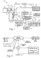
- FIG. 1 is a schematic of an on-board vehicle refrigeration system
- FIG. 2 is a block logic diagram for the controller of the system of FIG. 1;
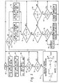
- FIG. 3 is a flow diagram of the algorithm for the controller of the system of FIG. 1;
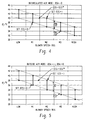
- FIG. 4 is a graph of temperature set point as a function of the system blower speed for the system of FIG. 1 for recirculation mode of operation;
- FIG. 5 is a graph similar to FIG. 4 of temperature set point as a function of blower speed for outside air directed over the evaporator for the system of FIG. 1.
- a typical on-board vehicle refrigerant system such as employed for the vehicle passenger compartment air conditioning, is illustrated generally at 10 and includes compressor 12 driven by a power source such as an engine driven belt 14 which is connected to the compressor by an electrically operated clutch 16 connected to an electrical controller 18 along leads 20,22.
- the controller is operated by an on-board vehicle electrical source 24.
- the compressor discharges along line 26 which is connected to the inlet of an exothermic heat exchanger or condenser 28 which discharges along line 30 to a receiver/drier 32 which provides refrigerant flow along line 34 to the inlet of an expander 36 which, in the present practice of the invention, comprises a fluid capsule operated thermal expansion valve as is well known in the art of motor vehicle air conditioning systems. It will be understood however, the present invention may alternatively be employed in a system utilizing a capillary tube or other type expander 36 in place of a thermal expansion valve.
- the low pressure outlet of the expander 36 is applied along line 38 to the inlet of an endothermic heat exchanger or evaporator 40.
- a temperature sensor which may be in the form of a thermistor or temperature transducer 42 is preferably disposed in line 44 at the outlet of evaporator 40 for sensing the temperature of the refrigerant discharging from the evaporator.
- the sensor may alternatively be disposed in the inlet line 38 of evaporator 40, as shown in dashed outline in Fig. 1 and denoted by reference numeral 42'.
- the evaporator discharges the superheated refrigerant along line 44 which is passed through the block of expander 36 for heat conduction purposes in a known manner and is returned to the compressor inlet along line 46.
- the controller 18 receives inputs from the user operated blower speed select switch 48 along line 49 and also from the user operated A/C on/off switch 50 and from the temperature sensor 42 along leads 52, 54. The controller also receives an input along line 52 from a user temperature select input 55. The controller 18 also receives an input from the user operated outside air/recirculation mode select control 56 which provides an input along line 58 to the controller and an ambient temperature signal along line 59 from ambient temperature sensor 57.
- the general operation of the controller 18 is indicated wherein the refrigerant temperature input T C from the sensor 42 is operative to enable a set point temperature calculation hereinafter described with reference to FIGS. 4 and 5 which the controller utilizes to determine whether the compressor clutch should be engaged or disengaged.
- the operation of the controller 18 is shown in a flow diagram wherein the system within the controller experiences initiation or Start at step 60 and moves to step 62 to select the sampling rate SR of the decision making and selects the sampling rate sr of data acquisition at step 64.
- the system then proceeds to read the inputs ACS, BSS, CCS, CCT, AQS at step 66 where ACS is the air conditioning selection, where zero represents OFF and one represents ON.
- BSS is the blower speed selection and has values low, M1, M2, M3, and high represented digitally by the integers 1 through 5.
- CCS is the compressor clutch status where zero represents the disengaged clutch and one represents the clutch engaged condition.
- CCS * represents the compressor clutch status at a previous sampling time.
- CCT is the cold control temperature as measured by the sensor or T c .
- AQS is the air quality status and is represented by the air flow vane position having a state OSA equals one for outside air flow into the passenger compartment; and, OSA equals zero for air recirculation flow in the passenger compartment.
- step 68 The system then proceeds to step 68 and asks the question whether BSS is zero; and, if the answer is affirmative returns to Start at step 60, but if the answer is negative the system proceeds to step 70 and asks the question whether ACS is zero. If the determination at step 70 is affirmative the system returns to Start at step 60; but, if the determination in step 70 is negative the system proceeds to step 72 and computes the average refrigerant temperature •. It will be understood that in the calculations for • according to the expressions shown in step 72 of FIG. 3, "i" is equal to the number of samples taken at the rate of "sr" of step 64. The system then proceeds to step 73 and asks if air flow is outside or if OSA equals one.
- step 74 finds the temperature set points ⁇ from a look-up table of values of BSS and AQS from FIG. 5. If, however, the determination at step 74 is negative, the system proceeds to step 75 and determines the temperature set points ⁇ from a look-up table in accordance with FIG. 4.
- Table I A simplified form of the lookup table is shown in Table I set forth below.
- step 76 The system having determined the temperature set points ⁇ at step 74 or step 75 proceeds to step 76 and asks the question whether the average temperature is equal to or greater than ⁇ or less than or equal to ⁇ plus an increment ⁇ . If the determination at step 76 is affirmative the system returns to step 60; and, if the determination at step 76 is negative the system proceeds to step 78 and asks whether the average temperature • is equal to or less than the set point ⁇ . If the determination at step 78 is negative the system proceeds to step 80 and asks whether the average temperature • is equal to or greater than ⁇ plus ⁇ and if not, the system returns to Start at step 60. If the determination at step 80 is affirmative the system proceeds to step 82 and asks whether CCS is equal to one, representing the compressor clutch engaged. If the determination at step 82 is affirmative, the system returns to Start at step 60; and, if negative the system proceeds to step 84 and engages the compressor clutch by setting CCS equal to one and returns to Start at step 60.
- step 78 determines whether the compressor clutch status is equal to one, and if the determination is negative, the system proceeds to maintain the compressor clutch status at CCS * at step 88. However, if the determination at step 86 is affirmative the system proceeds to disengage the compressor clutch at step 90 by setting CCS equal to zero and returning to Start at step 60.
- the present invention thus provides a technique for controlling the cycling of a compressor clutch for an automotive air conditioning system which minimizes the occurrence of evaporator freezing and the resultant long cycling of the compressor in an effort to provide cooling with the evaporator coated with ice.
- the present invention provides for optimizing the compressor clutch cycling from measurements of the temperature of the refrigerant discharging from the evaporator and calculating temperature set points based upon knowledge of the system from a lookup table based on user selected blower speed and air mode settings.
Landscapes
- Physics & Mathematics (AREA)
- Engineering & Computer Science (AREA)
- General Physics & Mathematics (AREA)
- Automation & Control Theory (AREA)
- Thermal Sciences (AREA)
- Mechanical Engineering (AREA)
- Air-Conditioning For Vehicles (AREA)
- Devices That Are Associated With Refrigeration Equipment (AREA)
Applications Claiming Priority (2)
| Application Number | Priority Date | Filing Date | Title |
|---|---|---|---|
| US492550 | 2000-01-27 | ||
| US09/492,550 US6260363B1 (en) | 2000-01-27 | 2000-01-27 | Control strategy for operating an on-board vehicle refrigeration system |
Publications (2)
| Publication Number | Publication Date |
|---|---|
| EP1120301A2 true EP1120301A2 (de) | 2001-08-01 |
| EP1120301A3 EP1120301A3 (de) | 2004-02-04 |
Family
ID=23956705
Family Applications (1)
| Application Number | Title | Priority Date | Filing Date |
|---|---|---|---|
| EP01101194A Withdrawn EP1120301A3 (de) | 2000-01-27 | 2001-01-24 | Regelstrategie zum Betreiben einer auf einem Fahrzeug montierte Kühlanlage |
Country Status (2)
| Country | Link |
|---|---|
| US (1) | US6260363B1 (de) |
| EP (1) | EP1120301A3 (de) |
Families Citing this family (7)
| Publication number | Priority date | Publication date | Assignee | Title |
|---|---|---|---|---|
| US20070251251A1 (en) * | 2006-04-26 | 2007-11-01 | Valeo Climate Control Corp. | HVAC heat exchanger freeze control means |
| US20090044557A1 (en) * | 2007-08-15 | 2009-02-19 | Johnson Controls Technology Company | Vapor compression system |
| US9243830B2 (en) * | 2009-03-03 | 2016-01-26 | Cleland Sales Corporation | Microprocessor-controlled beverage dispenser |
| US8209073B2 (en) * | 2009-05-06 | 2012-06-26 | Ford Global Technologies, Llc | Climate control system and method for optimizing energy consumption of a vehicle |
| US20110073281A1 (en) * | 2009-09-29 | 2011-03-31 | Keihin Corporation | Heat exchanger for vehicular air conditioning apparatus |
| US8830079B2 (en) * | 2011-06-29 | 2014-09-09 | Ford Global Technologies, Llc | Low air conditioning refrigerant detection method |
| US9796243B2 (en) | 2013-02-05 | 2017-10-24 | Ford Global Technologies, Llc | Coolest A/C discharge temperature for all operating conditions |
Family Cites Families (6)
| Publication number | Priority date | Publication date | Assignee | Title |
|---|---|---|---|---|
| JP2704009B2 (ja) * | 1989-10-19 | 1998-01-26 | マツダ株式会社 | 自動車の空調制御装置 |
| US5039009A (en) * | 1990-07-16 | 1991-08-13 | American Standard Inc. | Thermostat interface for a refrigeration system controller |
| JPH04270854A (ja) * | 1991-02-26 | 1992-09-28 | Hitachi Ltd | 空気調和機の制御方法 |
| US5490556A (en) * | 1993-06-09 | 1996-02-13 | Eagle Engineering And Manufacturing, Inc. | Off-road air conditioning control |
| JPH07212902A (ja) * | 1993-12-02 | 1995-08-11 | Nippondenso Co Ltd | 電気自動車の空調装置制御システム |
| US5546756A (en) * | 1995-02-08 | 1996-08-20 | Eaton Corporation | Controlling an electrically actuated refrigerant expansion valve |
-
2000
- 2000-01-27 US US09/492,550 patent/US6260363B1/en not_active Expired - Lifetime
-
2001
- 2001-01-24 EP EP01101194A patent/EP1120301A3/de not_active Withdrawn
Non-Patent Citations (1)
| Title |
|---|
| None |
Also Published As
| Publication number | Publication date |
|---|---|
| US6260363B1 (en) | 2001-07-17 |
| EP1120301A3 (de) | 2004-02-04 |
Similar Documents
| Publication | Publication Date | Title |
|---|---|---|
| US9341398B2 (en) | Air conditioning system provided with an electronic expansion valve | |
| EP0232188B1 (de) | Vorrichtung zur Steuerung der Kompressorkapazität | |
| CN101113834B (zh) | 空调机的控制方法 | |
| US4498310A (en) | Heat pump system | |
| US7275379B2 (en) | Automotive HVAC system and method of operating same utilizing enthalpy-based control | |
| US6293116B1 (en) | Humidity control method for a variable capacity vehicle climate control system | |
| US6058728A (en) | Refrigerant cycle for vehicle air conditioner | |
| US7886552B2 (en) | Compressor cycle control method for a vehicle air conditioning system | |
| US8682527B2 (en) | Cooling system compressor with variable operating range | |
| US5524444A (en) | Temperature control of an appliance using ambient air temperature determination | |
| US6786057B2 (en) | Vehicle air conditioning device using a supercritical cycle | |
| US6625997B1 (en) | Automotive air conditioning system | |
| US20100236265A1 (en) | Air conditioner for vehicle | |
| US6105387A (en) | Two pass evaporator | |
| US6260363B1 (en) | Control strategy for operating an on-board vehicle refrigeration system | |
| EP0654370B1 (de) | Verfahren und Vorrichtung zur Vermeidung der Bildung von kondensiertem Wasserdampf in Klimaanlagen | |
| US6694756B1 (en) | System and method for multi-stage dehumidification | |
| US20070251251A1 (en) | HVAC heat exchanger freeze control means | |
| US7181922B2 (en) | Automotive air conditioner | |
| JP2000111182A (ja) | 空調装置 | |
| US6378316B2 (en) | Method for checking the state of a closed loop air-conditioning system comprising a variable-throughput compressor | |
| US20240253423A1 (en) | Vehicular heat management system | |
| CN113263885B (zh) | 调节用于机动车的热泵的方法以及机动车的热泵和机动车 | |
| JPS63184519A (ja) | 車両用空気調和装置の制御装置 | |
| KR20180046158A (ko) | 저온 영역에서 성능이 개선된 차량용 에어컨디셔너 및 저온 영역에서의 차량용 에어컨디셔너의 제어방법 |
Legal Events
| Date | Code | Title | Description |
|---|---|---|---|
| PUAI | Public reference made under article 153(3) epc to a published international application that has entered the european phase |
Free format text: ORIGINAL CODE: 0009012 |
|
| AK | Designated contracting states |
Kind code of ref document: A2 Designated state(s): AT BE CH CY DE DK ES FI FR GB GR IE IT LI LU MC NL PT SE TR |
|
| AX | Request for extension of the european patent |
Free format text: AL;LT;LV;MK;RO;SI |
|
| PUAL | Search report despatched |
Free format text: ORIGINAL CODE: 0009013 |
|
| AK | Designated contracting states |
Kind code of ref document: A3 Designated state(s): AT BE CH CY DE DK ES FI FR GB GR IE IT LI LU MC NL PT SE TR |
|
| AX | Request for extension of the european patent |
Extension state: AL LT LV MK RO SI |
|
| RIC1 | Information provided on ipc code assigned before grant |
Ipc: 7B 60H 1/00 B Ipc: 7B 60H 1/32 A |
|
| AKX | Designation fees paid | ||
| REG | Reference to a national code |
Ref country code: DE Ref legal event code: 8566 |
|
| STAA | Information on the status of an ep patent application or granted ep patent |
Free format text: STATUS: THE APPLICATION IS DEEMED TO BE WITHDRAWN |
|
| 18D | Application deemed to be withdrawn |
Effective date: 20040803 |