EP1120480A2 - Système de revêtement amélioré pour aubes de turbine - Google Patents
Système de revêtement amélioré pour aubes de turbine Download PDFInfo
- Publication number
- EP1120480A2 EP1120480A2 EP01300567A EP01300567A EP1120480A2 EP 1120480 A2 EP1120480 A2 EP 1120480A2 EP 01300567 A EP01300567 A EP 01300567A EP 01300567 A EP01300567 A EP 01300567A EP 1120480 A2 EP1120480 A2 EP 1120480A2
- Authority
- EP
- European Patent Office
- Prior art keywords
- coating
- superalloy
- airfoil
- group
- tightly adherent
- Prior art date
- Legal status (The legal status is an assumption and is not a legal conclusion. Google has not performed a legal analysis and makes no representation as to the accuracy of the status listed.)
- Granted
Links
Images

Classifications
-
- C—CHEMISTRY; METALLURGY
- C23—COATING METALLIC MATERIAL; COATING MATERIAL WITH METALLIC MATERIAL; CHEMICAL SURFACE TREATMENT; DIFFUSION TREATMENT OF METALLIC MATERIAL; COATING BY VACUUM EVAPORATION, BY SPUTTERING, BY ION IMPLANTATION OR BY CHEMICAL VAPOUR DEPOSITION, IN GENERAL; INHIBITING CORROSION OF METALLIC MATERIAL OR INCRUSTATION IN GENERAL
- C23C—COATING METALLIC MATERIAL; COATING MATERIAL WITH METALLIC MATERIAL; SURFACE TREATMENT OF METALLIC MATERIAL BY DIFFUSION INTO THE SURFACE, BY CHEMICAL CONVERSION OR SUBSTITUTION; COATING BY VACUUM EVAPORATION, BY SPUTTERING, BY ION IMPLANTATION OR BY CHEMICAL VAPOUR DEPOSITION, IN GENERAL
- C23C28/00—Coating for obtaining at least two superposed coatings either by methods not provided for in a single one of groups C23C2/00 - C23C26/00 or by combinations of methods provided for in subclasses C23C and C25C or C25D
- C23C28/30—Coatings combining at least one metallic layer and at least one inorganic non-metallic layer
- C23C28/32—Coatings combining at least one metallic layer and at least one inorganic non-metallic layer including at least one pure metallic layer
- C23C28/321—Coatings combining at least one metallic layer and at least one inorganic non-metallic layer including at least one pure metallic layer with at least one metal alloy layer
- C23C28/3215—Coatings combining at least one metallic layer and at least one inorganic non-metallic layer including at least one pure metallic layer with at least one metal alloy layer at least one MCrAlX layer
-
- C—CHEMISTRY; METALLURGY
- C23—COATING METALLIC MATERIAL; COATING MATERIAL WITH METALLIC MATERIAL; CHEMICAL SURFACE TREATMENT; DIFFUSION TREATMENT OF METALLIC MATERIAL; COATING BY VACUUM EVAPORATION, BY SPUTTERING, BY ION IMPLANTATION OR BY CHEMICAL VAPOUR DEPOSITION, IN GENERAL; INHIBITING CORROSION OF METALLIC MATERIAL OR INCRUSTATION IN GENERAL
- C23C—COATING METALLIC MATERIAL; COATING MATERIAL WITH METALLIC MATERIAL; SURFACE TREATMENT OF METALLIC MATERIAL BY DIFFUSION INTO THE SURFACE, BY CHEMICAL CONVERSION OR SUBSTITUTION; COATING BY VACUUM EVAPORATION, BY SPUTTERING, BY ION IMPLANTATION OR BY CHEMICAL VAPOUR DEPOSITION, IN GENERAL
- C23C16/00—Chemical coating by decomposition of gaseous compounds, without leaving reaction products of surface material in the coating, i.e. chemical vapour deposition [CVD] processes
- C23C16/22—Chemical coating by decomposition of gaseous compounds, without leaving reaction products of surface material in the coating, i.e. chemical vapour deposition [CVD] processes characterised by the deposition of inorganic material, other than metallic material
- C23C16/30—Deposition of compounds, mixtures or solid solutions, e.g. borides, carbides, nitrides
- C23C16/40—Oxides
- C23C16/405—Oxides of refractory metals or yttrium
-
- C—CHEMISTRY; METALLURGY
- C23—COATING METALLIC MATERIAL; COATING MATERIAL WITH METALLIC MATERIAL; CHEMICAL SURFACE TREATMENT; DIFFUSION TREATMENT OF METALLIC MATERIAL; COATING BY VACUUM EVAPORATION, BY SPUTTERING, BY ION IMPLANTATION OR BY CHEMICAL VAPOUR DEPOSITION, IN GENERAL; INHIBITING CORROSION OF METALLIC MATERIAL OR INCRUSTATION IN GENERAL
- C23C—COATING METALLIC MATERIAL; COATING MATERIAL WITH METALLIC MATERIAL; SURFACE TREATMENT OF METALLIC MATERIAL BY DIFFUSION INTO THE SURFACE, BY CHEMICAL CONVERSION OR SUBSTITUTION; COATING BY VACUUM EVAPORATION, BY SPUTTERING, BY ION IMPLANTATION OR BY CHEMICAL VAPOUR DEPOSITION, IN GENERAL
- C23C28/00—Coating for obtaining at least two superposed coatings either by methods not provided for in a single one of groups C23C2/00 - C23C26/00 or by combinations of methods provided for in subclasses C23C and C25C or C25D
- C23C28/30—Coatings combining at least one metallic layer and at least one inorganic non-metallic layer
- C23C28/34—Coatings combining at least one metallic layer and at least one inorganic non-metallic layer including at least one inorganic non-metallic material layer, e.g. metal carbide, nitride, boride, silicide layer and their mixtures, enamels, phosphates and sulphates
- C23C28/345—Coatings combining at least one metallic layer and at least one inorganic non-metallic layer including at least one inorganic non-metallic material layer, e.g. metal carbide, nitride, boride, silicide layer and their mixtures, enamels, phosphates and sulphates with at least one oxide layer
- C23C28/3455—Coatings combining at least one metallic layer and at least one inorganic non-metallic layer including at least one inorganic non-metallic material layer, e.g. metal carbide, nitride, boride, silicide layer and their mixtures, enamels, phosphates and sulphates with at least one oxide layer with a refractory ceramic layer, e.g. refractory metal oxide, ZrO2, rare earth oxides or a thermal barrier system comprising at least one refractory oxide layer
-
- F—MECHANICAL ENGINEERING; LIGHTING; HEATING; WEAPONS; BLASTING
- F01—MACHINES OR ENGINES IN GENERAL; ENGINE PLANTS IN GENERAL; STEAM ENGINES
- F01D—NON-POSITIVE DISPLACEMENT MACHINES OR ENGINES, e.g. STEAM TURBINES
- F01D25/00—Component parts, details, or accessories, not provided for in, or of interest apart from, other groups
- F01D25/007—Preventing corrosion
-
- F—MECHANICAL ENGINEERING; LIGHTING; HEATING; WEAPONS; BLASTING
- F01—MACHINES OR ENGINES IN GENERAL; ENGINE PLANTS IN GENERAL; STEAM ENGINES
- F01D—NON-POSITIVE DISPLACEMENT MACHINES OR ENGINES, e.g. STEAM TURBINES
- F01D5/00—Blades; Blade-carrying members; Heating, heat-insulating, cooling or antivibration means on the blades or the members
- F01D5/12—Blades
- F01D5/28—Selecting particular materials; Particular measures relating thereto; Measures against erosion or corrosion
- F01D5/288—Protective coatings for blades
-
- F—MECHANICAL ENGINEERING; LIGHTING; HEATING; WEAPONS; BLASTING
- F02—COMBUSTION ENGINES; HOT-GAS OR COMBUSTION-PRODUCT ENGINE PLANTS
- F02C—GAS-TURBINE PLANTS; AIR INTAKES FOR JET-PROPULSION PLANTS; CONTROLLING FUEL SUPPLY IN AIR-BREATHING JET-PROPULSION PLANTS
- F02C7/00—Features, components parts, details or accessories, not provided for in, or of interest apart form groups F02C1/00 - F02C6/00; Air intakes for jet-propulsion plants
- F02C7/30—Preventing corrosion or unwanted deposits in gas-swept spaces
-
- F—MECHANICAL ENGINEERING; LIGHTING; HEATING; WEAPONS; BLASTING
- F05—INDEXING SCHEMES RELATING TO ENGINES OR PUMPS IN VARIOUS SUBCLASSES OF CLASSES F01-F04
- F05D—INDEXING SCHEME FOR ASPECTS RELATING TO NON-POSITIVE-DISPLACEMENT MACHINES OR ENGINES, GAS-TURBINES OR JET-PROPULSION PLANTS
- F05D2230/00—Manufacture
- F05D2230/90—Coating; Surface treatment
-
- Y—GENERAL TAGGING OF NEW TECHNOLOGICAL DEVELOPMENTS; GENERAL TAGGING OF CROSS-SECTIONAL TECHNOLOGIES SPANNING OVER SEVERAL SECTIONS OF THE IPC; TECHNICAL SUBJECTS COVERED BY FORMER USPC CROSS-REFERENCE ART COLLECTIONS [XRACs] AND DIGESTS
- Y02—TECHNOLOGIES OR APPLICATIONS FOR MITIGATION OR ADAPTATION AGAINST CLIMATE CHANGE
- Y02T—CLIMATE CHANGE MITIGATION TECHNOLOGIES RELATED TO TRANSPORTATION
- Y02T50/00—Aeronautics or air transport
- Y02T50/60—Efficient propulsion technologies, e.g. for aircraft
Definitions
- This invention is related to environmental and thermal barrier coating systems exposed to high temperatures such as the hostile thermal environment of a gas turbine engine. More particularly, the present invention is directed to a layer applied over the environmental layer or the thermal barrier layer of an airfoil that reduces the build-up of corrosive materials on the outer surface of the airfoil.
- Nickel aluminide coatings applied by a codeposition (Codep) process.
- Codep codeposition
- the preferred coating for protection against oxidation and hot corrosion that has evolved is a nickel-platinum aluminide application in which a layer of platinum is deposited over the substrate followed by an aluminizing application.
- the aluminide may be applied by a Codep process or by a vapor phase aluminide process.
- the resulting coating is a graded composition of (Ni, Pt)AI.
- the MCrAIY class of coatings were developed, where M is an element selected from the group consisting of Ni, Co, Fe and combinations thereof.
- U.S. Patent No. 5,891,267 forms a carburized zone below an alumina layer in order to tie up refractory metals present in the underlying superalloy substrate to that these elements will not migrate to detrimentally affect he bond coat-oxide layer interface and accelerate corrosion of the substrate.
- U.S. patent No. 5,952,085 to Rickerby, et al. in which multiple erosion resistant coatings are applied over substrates by spattering to improve erosion resistance.
- These alternating layers are comprised of tungsten (W) and titanium diboride. The alternating layers are between 0.3-1 micron thick.
- What is needed is a coating that can be used on turbine components that is effective in reducing the build-up of corrosive materials on all portions of the component and that can enhance the environmental protection of currently applied bond coatings and environmental coatings.
- the present invention is generally applicable to components that operate in high temperature environments in which there is exposure to hot gases of combustion that can cause corrosion of the components, including oxidation such as are found in gas turbine engines. Improvements in manufacturing technology and materials are the keys to increased performance and reduced costs for many articles including those used in gas turbine engines. As an example, continuing and often interrelated improvements in processes and materials have resulted in major increases in the performance of aircraft gas turbine engines that result in even higher operating temperatures for these engines. As the operating temperatures increase, the effects of the high temperature environment are observed in regions beyond the portions extending immediately into the hot stream of gases, previously the airfoil portions of blades and vanes. Over time, these conditions ultimately can cause the deterioration of even the protective coatings applied to substrates to improve their performance.
- the hot gases of combustion may additionally deposit products of combustion onto surfaces of the components that may contribute to the corrosion of the component.
- Notable examples of such components include airfoils such as turbine blades or buckets and turbine vanes.
- the present invention is not limited to airfoils as other components that can benefit from the present invention include combustors, combustor liners and turbine shrouds.
- the present invention is a tightly adherent coating that provides a surface that is described as anti-stick in that products of combustion and other deposits that may be present in hot gases of combustion to not deposit on it.
- This tightly adherent coating is applied over the component and assists the component operating at high temperatures by increasing its life expectancy.
- the coating can provide additional protection to the underlying component even at the elevated temperatures and extreme environments found in the portion of the turbine engine aft of the combustor. While not impervious to diffusion of oxygen, the coating does act to slow the diffusion of oxygen to the underlying coatings, thereby extending the life of these coatings by slowing the inevitable process of deterioration.
- Substrate articles designed to survive in this environment are comprised of superalloys having the required mechanical properties that are especially engineered and designed to be able to withstand the harsh environments and high temperatures.
- coatings are applied over the superalloy substrate.
- the coating of the present invention can be applied directly over these tightly adherent coatings to delay their deterioration over time and increase their life expectancy.
- the tightly adherent coating that overlies the substrate component is a thin, tightly adherent oxide layer formed by the oxidation of at least one metal from groups 4b or 5b, certain elements of group 4a of the Periodic Table of elements, platinum (Pt) and tungsten (W) or combinations of these metals.
- Pt platinum
- W tungsten
- An advantage of the present invention is that the antistick coating in not only hard, durable and capable of withstanding high temperatures, but it also very light. Thus, the longer life of the components can be achieved with no weight penalties with the present invention.
- the very thin coating allows for its use on components have cooling channels and other openings without concern about blocking important cooling openings so that special precautions or preparation is not required for its application.
- the minimal thickness of the coating also has a minimal effect on the dimensioning and tolerancing of the parts to which it is applied.
- Another advantage of the present invention is that it is compatible with the materials utilized in the turbine portions of gas turbine engines. These materials include the specially engineered superalloys as well as the environmental coatings and bond coatings typically applied to these superalloys to extend their life and to the ceramic thermal barrier coatings applied over these coatings to improve the thermal performance of these components.
- Yet another advantage of the coating of the present invention is that it is inexpensive in comparison to the cost of coatings including MCrAIY coatings and platinum aluminide coatings. And although the coatings of the present invention are not designed to replace such coatings in the airfoil portions of components, they can extend the life of such coatings thereby reducing overall operating costs. Because the coatings of the present invention minimize the deterioration of the expensive MCrAIY coatings and platinum aluminide coatings, refurbishment of these coatings may be accomplished at reduced costs without the need for complete removal.
- a tightly adherent coating applied over a superalloy turbine component exposed to hot gases of combustion improves the ability of the superalloy component to resist the accumulation of deposits such as products of combustion.
- the ability of the superalloy component to resist the accumulation of deposits on its surface is an indication of the anti-stick characteristics of the surface.
- a coating applied to a component that improves the anti-stick characteristics of the surface of the component is referred to as an anti-stick coating.
- the present invention thus comprises a substrate article formed of a high temperature alloy engineered to withstand high temperatures and accompanying corrosive environments.
- these high temperature alloys are superalloys such as the Rene series, Rene 80, Rene N4, Rene N5 and Rene N6, MAR-M-509, IN-718, UDIMET 720, L605 and IN-738.
- MAR- M-509 has a nominal composition by weight of 10% Ni, 0.6% C, 0.1% Mn, 0.4% Si, 22.5% Cr, 1.5% Fe, 0.01% B, 0.5% Zr, 7% W, 3.5% Ta and the balance Co and incidental impurities;
- L605 has a nominal composition by weight of 20% Cr, 10% Ni, 15% W, 3% Fe, 1%, Si, 1.5% Mn, 0.1% C, and the balance Ni and incidental impurities; Rene N5, has a nominal composition by weight of 7.5% Co, 7% Cr, 6.2% Al, 6.5% Ta, 5% W, 3% Re, 1.5% Mo, 0.15% Hf, 0.05% C, 0.004% B and the balance Ni and incidental impurities; and IN-738 has a nominal composition by weight of 8.5% Co, 16% Cr, 3.4% Al, 3.8% Ti, 1.75% Ta, 2.6% W, 1.75% Ta, 0.012% B . 0.12% Zr, .05% Cb and the balance Ni and incidental impurities.
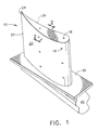
- Fig. 1 is a perspective view of a typical superalloy airfoil component, a turbine blade 10.
- the superalloy blade substrate is comprised of an airfoil portion 20 that extends outward into the hot gases of combustion found in aircraft exhaust, a platform portion 30 and a dovetail or shank portion 40.
- Turbine blades 10 including cooling holes 18 typically have an environmental coating 22 such as an MCrAIY or an aluminide applied over the airfoil portion 20.
- the tip 24 of the airfoil portion 20 includes a columnar-grained ceramic thermal barrier coating 26, such as YSZ, overlying the environmental coating 22 that also serves as a bond coating.
- the coatings 22, 26 overlying the airfoil substrate portion 20 in the vicinity of the tip are shown in cross section in Fig. 2, and are typical of coatings, when present, overlying substrates. There are circumstances in which an environmental coating 22 is extended downward over platform portion 30, and even partially or fully downward over shank portion 40.
- the portion of the article exposed to the hot gases of combustion found aft of the combustor portion of the gas turbine engine typically are coated with an environmental coating 22 to protect the substrate from the corrosive and oxidative effects of the hot gases. Most typically, these coatings 22 are tightly adherent. These coatings 22 usually are classified as aluminides or MCrAIYs and are applied to the airfoil portion 20 of turbine blades and vanes, and to the surfaces of liners exposed to hot turbine gases.
- Aluminides are intermetallic compounds formed on the surface of the substrate by a number of different available processes including but not limited to diffusion methods. Aluminides are selected from the group consisting of nickel aluminides, platinum aluminides and combinations thereof.
- MCrAIY coatings are deposited on the surface of the substrate where M is at least one element selected from the group consisting of nickel, cobalt and iron. As the temperature of the exhaust gases has increased, the coatings have been extended to portions of components such as the platform portion of blades 30 and the shank portion of blades 40 not directly in the flow of the hot gases of combustion that heretofore had not experienced problems with oxidation and hot corrosion.
- Ceramic thermal barriers are grown over the environmental coating 22.
- These ceramic thermal barrier coatings 26 are typically made from yttrium-stabilized zirconia (YSZ).
- the present invention can be applied directly over these pre-coated surfaces to improve their performance in environments in which oxidation and corrosion are a problem.
- the anti-stick coating of the present invention is a thin, tightly adherent metallic oxide formed by an oxide of at least one metal selected from group 4b and 5b and several of the elements of group 4a of the Periodic Table as well as Pt and W. These elements include from group 5b, tantalum (Ta), niobium (columbium) (Nb), vanadium (V), from group 4b, hafnium (Hf), zirconium (Zr), titanium (Ti), and group 4a, germanium (Ge), silicon (Si) and tin (Sn).
- the metallic oxide can be formed directly over the surfaces of the superalloy substrate component. To be considered for use in a particular application, the metallic oxide must be stable at the maximum temperatures experienced in the application.
- the anti-stick coating is deposited directly onto the outer surface of the component in the gas flowpath which usually already includes environmental coatings 22 and onto portions of components that are not in the direct flowpath of hot gases of combustion, such as the shank portion 40 and the platform portion 30 of turbine airfoils 10.
- These environmental coatings 22 include platinum aluminides, nickel aluminides, combinations of these, (Ni,Pt)AI coatings and MCrAIY coatings.
- the anti-stick coatings 28 of the present invention can be applied directly over ceramic thermal barrier coatings 26 (TBCs) when these TBCs form the outer surface of the component.
- TBCs ceramic thermal barrier coatings 26
- the application of the anti-stick coating 28 reduces the build-up of corrosive materials that would otherwise adhere to the outer surface of the component.
- These corrosive materials can include hot products of combustion that contain a variety of detrimental elements including but not limited to elements such as sulfur and phosphorus.
- the anti-stick coating by reducing or eliminating the presence of these products, minimizes or eliminates their ability to attack the underlying coating and substrate.
- the anti-stick coating 28 also provides an additional benefit as a barrier to oxygen.
- the anti-stick coating is not impervious to oxygen, it does shield the underlying coating and substrate from direct contact with gases that oxidize these surfaces. Although oxidation will still occur, the rate of the oxidation reaction is slowed since diffusion through the anti-stick layer reduces the flow of available oxygen.
- the tightly adherent anti-stick layer that is a metallic oxide formed from at least one metal selected from group 4b and 5b, Si, Ge, or Sn of group 4a and W or Pt provides virtually no weight penalty to the turbine components to which it is applied, as it is very thin.
- the metallic oxide is applied in thicknesses of no greater than 10 microns. If the anti-stick layer is applied in thicknesses greater than 10 microns, it has a tendency to spall from the surface as hot gases pass over it at high velocities and elevated temperatures. This critical thickness of the layer thus is important to its ability to tightly adhere to the substrate. And of course, a thin coating is desirable because of on-going concerns with weight.
- the thickness of the coating is not greater than about 5 microns, and most preferably is from about 0.5-2 microns in thickness.
- the coating can be applied by any method that achieves a uniform, tightly adherent coating of the desired thickness.
- turbine airfoils 10 that included environmental/bond coatings 22 applied over the airfoil portion 20, at least a part of the shank portion 40 and the platform portion 30, and that additionally included a YSZ thermal barrier coating 26 applied over the tip 24 of airfoil portion 20 was prepared for coating with the anti-stick layer of the present invention by cleaning the airfoils with a suitable solvent to remove loose dirt, grease, oils and other foreign materials. Any suitable well-known solvent can be used to accomplish the task, as the presence of these materials can interfere with the adherence and continuity of the coating.
- the airfoils were then placed in a CVD coater.
- the CVD coater was capable of handling a plurality of blades, however, if desired, the blades may be coated individually in the CVD coater.
- the CVD chamber was then purged of oxygen by introduction of an inert gas or nitrogen.
- the temperature of the chamber was increased to a temperature in the range of 720-900°F (382-482°C). The temperature selected will vary depending upon the coating to be applied and will be above about 500°F (260°C).
- a carrier gas that was a mixture of a precursor gas that included the precursor material and an inert gas or nitrogen was introduced.
- the carrier gas is a mixture of the precursor gas and the same gas used for purging the chamber.
- the precursor gas was tantalum ethoxide having a partial pressure of about 50-500 microinches of mercury.
- the flow of gases was continued for a time sufficient to achieve a coating 28 of the desired thickness. This time can be calculated with very good accuracy.
- the flow of gas was maintained until a thickness of tantalum oxide of 0.5-1 micron was achieved. The time for such a thickness at these above temperatures is from 1-3 hours. Thicker coatings naturally will require higher temperatures or longer times or both.
- Fig. 2 shows the anti-stick coating 28 of the present invention overlying only the ceramic topcoat 26 in cross-section. However, the coating of the present invention is applied to all portions of the component that are not masked to prevent its application.
- substrates of Rene 80, INCO 718 and UDIMET 720 were standard plate samples otherwise prepared as a standard airfoil component. However, one set of substrates was treated by depositing an anti-stick coating of tantalum oxide over the substrates to a thickness of 1 micron using parameters noted above. Hot corrosion tests were performed at 1700°F (927°C) in an environment of calcium sulfate in accordance with established test procedures. Failure of the substrates is determined by the amount of time required for corrosion to penetrate a predetermined amount, about 0.001", into the substrate.
- the amount of time for the corrosion to penetrate to this depth took ten times longer for the substrates coated with tantalum oxide in accordance with the present invention than for substrates not having a coating of the present invention.
- the corrosion resistance of the substrates that were coated with the anti-stick coating of the present invention had an expected life that was 10 times longer than substrates not having an anti-stick coating.
Landscapes
- Chemical & Material Sciences (AREA)
- Engineering & Computer Science (AREA)
- Mechanical Engineering (AREA)
- Inorganic Chemistry (AREA)
- Materials Engineering (AREA)
- Chemical Kinetics & Catalysis (AREA)
- Metallurgy (AREA)
- Organic Chemistry (AREA)
- General Engineering & Computer Science (AREA)
- Combustion & Propulsion (AREA)
- Ceramic Engineering (AREA)
- General Chemical & Material Sciences (AREA)
- Turbine Rotor Nozzle Sealing (AREA)
- Other Surface Treatments For Metallic Materials (AREA)
Applications Claiming Priority (2)
| Application Number | Priority Date | Filing Date | Title |
|---|---|---|---|
| US489716 | 2000-01-24 | ||
| US09/489,716 US6394755B1 (en) | 2000-01-24 | 2000-01-24 | Enhanced coating system for turbine airfoil applications |
Publications (3)
| Publication Number | Publication Date |
|---|---|
| EP1120480A2 true EP1120480A2 (fr) | 2001-08-01 |
| EP1120480A3 EP1120480A3 (fr) | 2001-11-28 |
| EP1120480B1 EP1120480B1 (fr) | 2010-08-18 |
Family
ID=23944991
Family Applications (1)
| Application Number | Title | Priority Date | Filing Date |
|---|---|---|---|
| EP01300567A Expired - Lifetime EP1120480B1 (fr) | 2000-01-24 | 2001-01-23 | Système de revêtement amélioré pour aubes de turbine |
Country Status (3)
| Country | Link |
|---|---|
| US (2) | US6394755B1 (fr) |
| EP (1) | EP1120480B1 (fr) |
| DE (1) | DE60142813D1 (fr) |
Cited By (2)
| Publication number | Priority date | Publication date | Assignee | Title |
|---|---|---|---|---|
| GB2436130A (en) * | 2005-12-15 | 2007-09-19 | Rolls Royce Plc | Stator vane arrangement with anti-bonding layer |
| EP2614885A1 (fr) * | 2004-05-05 | 2013-07-17 | Siemens Energy, Inc. | Revêtement catalytiquement actif et procédé de dépôt sur un substrat |
Families Citing this family (20)
| Publication number | Priority date | Publication date | Assignee | Title |
|---|---|---|---|---|
| US6582834B2 (en) * | 2001-06-12 | 2003-06-24 | General Electric Company | Anti-stick coating for internal passages of turbine components |
| US6532657B1 (en) * | 2001-09-21 | 2003-03-18 | General Electric Co., | Pre-service oxidation of gas turbine disks and seals |
| US6933066B2 (en) * | 2002-12-12 | 2005-08-23 | General Electric Company | Thermal barrier coating protected by tantalum oxide and method for preparing same |
| CA2442780C (fr) * | 2002-12-13 | 2007-12-11 | Sulzer Chemtech Ag | Melangeur statique pour milieu a viscosite elevee |
| US6884461B2 (en) * | 2002-12-20 | 2005-04-26 | General Electric Company | Turbine nozzle with heat rejection coats |
| US6884515B2 (en) * | 2002-12-20 | 2005-04-26 | General Electric Company | Afterburner seals with heat rejection coats |
| US6884460B2 (en) * | 2002-12-20 | 2005-04-26 | General Electric Company | Combustion liner with heat rejection coats |
| US7285312B2 (en) * | 2004-01-16 | 2007-10-23 | Honeywell International, Inc. | Atomic layer deposition for turbine components |
| US7473072B2 (en) * | 2005-02-01 | 2009-01-06 | Honeywell International Inc. | Turbine blade tip and shroud clearance control coating system |
| US20060246319A1 (en) * | 2005-05-02 | 2006-11-02 | Honeywell International, Inc. | Impact-resistant multilayer coating |
| EP1775422A1 (fr) * | 2005-10-17 | 2007-04-18 | Siemens Aktiengesellschaft | Dispositif de canal d'écoulement et procédé de revêtement d'un dispositif de canal d'écoulement |
| US8707323B2 (en) * | 2005-12-30 | 2014-04-22 | Sap Ag | Load balancing algorithm for servicing client requests |
| US7597934B2 (en) * | 2006-02-21 | 2009-10-06 | General Electric Company | Corrosion coating for turbine blade environmental protection |
| US7740948B1 (en) * | 2006-05-31 | 2010-06-22 | The United States Of America As Represented By The United States Department Of Energy | Thermal barrier coatings |
| US8714932B2 (en) * | 2008-12-31 | 2014-05-06 | General Electric Company | Ceramic matrix composite blade having integral platform structures and methods of fabrication |
| US20130323518A1 (en) * | 2012-06-05 | 2013-12-05 | General Electric Company | Coating process, coating, and coated component |
| US9017815B2 (en) | 2012-09-13 | 2015-04-28 | Ppg Industries Ohio, Inc. | Near-infrared radiation curable multilayer coating systems and methods for applying same |
| US10775115B2 (en) | 2013-08-29 | 2020-09-15 | General Electric Company | Thermal spray coating method and thermal spray coated article |
| CA3206459A1 (fr) * | 2020-12-15 | 2022-06-23 | Oerlikon Surface Solutions Ag, Pfaffikon | Revetement pour aubes de turbine a charge thermique et abrasive |
| CN114134458A (zh) * | 2021-12-08 | 2022-03-04 | 上海交通大学 | 一种具有纳米多孔结构的周期性多层超薄隔热薄膜及其制备和应用 |
Citations (1)
| Publication number | Priority date | Publication date | Assignee | Title |
|---|---|---|---|---|
| US5350599A (en) | 1992-10-27 | 1994-09-27 | General Electric Company | Erosion-resistant thermal barrier coating |
Family Cites Families (13)
| Publication number | Priority date | Publication date | Assignee | Title |
|---|---|---|---|---|
| US5015502A (en) * | 1988-11-03 | 1991-05-14 | Allied-Signal Inc. | Ceramic thermal barrier coating with alumina interlayer |
| US4916022A (en) * | 1988-11-03 | 1990-04-10 | Allied-Signal Inc. | Titania doped ceramic thermal barrier coatings |
| US5238752A (en) * | 1990-05-07 | 1993-08-24 | General Electric Company | Thermal barrier coating system with intermetallic overlay bond coat |
| US5180285A (en) * | 1991-01-07 | 1993-01-19 | Westinghouse Electric Corp. | Corrosion resistant magnesium titanate coatings for gas turbines |
| US5891584A (en) * | 1991-03-25 | 1999-04-06 | General Electric Company | Coated article for hot hydrocarbon fluid and method of preventing fuel thermal degradation deposits |
| US5805973A (en) * | 1991-03-25 | 1998-09-08 | General Electric Company | Coated articles and method for the prevention of fuel thermal degradation deposits |
| CA2105188A1 (fr) * | 1992-09-22 | 1994-03-23 | George A. Coffinberry | Article revetu destine a un fluide hydrocarbone chaud, et methode servant a prevenir les depots produits par la degradation thermique du combustible |
| EP0607651B1 (fr) * | 1993-01-15 | 1998-01-07 | General Electric Company | Prévention des dépÔts de carburant formés par décomposition thermique |
| CA2113366C (fr) * | 1993-01-15 | 2005-11-08 | George A. Coffinberry | Articles enduits et methode de prevention contre la degradation thermique par des depots combustibles |
| US5952085A (en) | 1994-03-23 | 1999-09-14 | Rolls-Royce Plc | Multiple layer erosion resistant coating and a method for its production |
| GB9426257D0 (en) | 1994-12-24 | 1995-03-01 | Rolls Royce Plc | Thermal barrier coating for a superalloy article and method of application |
| US5891267A (en) | 1997-01-16 | 1999-04-06 | General Electric Company | Thermal barrier coating system and method therefor |
| US5876860A (en) * | 1997-12-09 | 1999-03-02 | N.V. Interturbine | Thermal barrier coating ceramic structure |
-
2000
- 2000-01-24 US US09/489,716 patent/US6394755B1/en not_active Expired - Fee Related
-
2001
- 2001-01-23 DE DE60142813T patent/DE60142813D1/de not_active Expired - Lifetime
- 2001-01-23 EP EP01300567A patent/EP1120480B1/fr not_active Expired - Lifetime
-
2002
- 2002-05-03 US US10/138,452 patent/US20020127112A1/en not_active Abandoned
Patent Citations (1)
| Publication number | Priority date | Publication date | Assignee | Title |
|---|---|---|---|---|
| US5350599A (en) | 1992-10-27 | 1994-09-27 | General Electric Company | Erosion-resistant thermal barrier coating |
Cited By (4)
| Publication number | Priority date | Publication date | Assignee | Title |
|---|---|---|---|---|
| EP2614885A1 (fr) * | 2004-05-05 | 2013-07-17 | Siemens Energy, Inc. | Revêtement catalytiquement actif et procédé de dépôt sur un substrat |
| GB2436130A (en) * | 2005-12-15 | 2007-09-19 | Rolls Royce Plc | Stator vane arrangement with anti-bonding layer |
| GB2436130B (en) * | 2005-12-15 | 2008-01-30 | Rolls Royce Plc | A vane arrangement and a method of making vane arrangement |
| US7837444B2 (en) | 2005-12-15 | 2010-11-23 | Rolls-Royce Plc | Vane arrangement and a method of making vane arrangement |
Also Published As
| Publication number | Publication date |
|---|---|
| US20020127112A1 (en) | 2002-09-12 |
| EP1120480B1 (fr) | 2010-08-18 |
| DE60142813D1 (de) | 2010-09-30 |
| US6394755B1 (en) | 2002-05-28 |
| EP1120480A3 (fr) | 2001-11-28 |
Similar Documents
| Publication | Publication Date | Title |
|---|---|---|
| US6394755B1 (en) | Enhanced coating system for turbine airfoil applications | |
| EP1652959B1 (fr) | Procédé de fabrication des revêtements d'aluminide de nickel de phase gamma prime | |
| JP4191427B2 (ja) | 改良プラズマ溶射熱ボンドコート系 | |
| US7247393B2 (en) | Gamma prime phase-containing nickel aluminide coating | |
| US6255001B1 (en) | Bond coat for a thermal barrier coating system and method therefor | |
| EP0979881B1 (fr) | Systeme de revêtement a barrière thermique comportant un revêtement de liaison à base d'un composite d'un métal et un oxyde de métal | |
| US6933052B2 (en) | Diffusion barrier and protective coating for turbine engine component and method for forming | |
| US7326441B2 (en) | Coating systems containing beta phase and gamma-prime phase nickel aluminide | |
| US6746782B2 (en) | Diffusion barrier coatings, and related articles and processes | |
| US6458473B1 (en) | Diffusion aluminide bond coat for a thermal barrier coating system and method therefor | |
| US20040079648A1 (en) | Method of depositing an oxidation and fatigue resistant MCrAIY-coating | |
| EP1652967A1 (fr) | Système de revêtement, comprenant une couche contient aluminide de nickel de phase gamma prime | |
| CA2292370C (fr) | Revetement ameliore et methode pour reduire au minimum la consommation de matiere de base pendant son utilisation a haute temperature | |
| EP1806433A2 (fr) | Couche de diffusion et procédé de fabrication | |
| GB2444611A (en) | Coating systems containing rhodium aluminide based layers | |
| EP1411148A1 (fr) | Procédé pour la déposition d'un couche de liaison à base de MCrAlY sur un article et l'article revêtu obtenu par ce procédé | |
| US7250225B2 (en) | Gamma prime phase-containing nickel aluminide coating | |
| EP1634977A1 (fr) | Procédé pour prévenir la formation d'une zone de réaction secondaire (ZRS) et système de couches correspondant | |
| US6974637B2 (en) | Ni-base superalloy having a thermal barrier coating system | |
| EP1008672A1 (fr) | Couche de liaison d'aluminiure au platine obtenue par diffusion pour revêtement dit de barrière thermique | |
| EP1217096B1 (fr) | Couche intermédiaire entre HR-120 et revêtements métalliques résistants à l'oxydation contenant de l'aluminium | |
| Wood et al. | High temperature coating for improved oxidation/corrosion protection |
Legal Events
| Date | Code | Title | Description |
|---|---|---|---|
| PUAI | Public reference made under article 153(3) epc to a published international application that has entered the european phase |
Free format text: ORIGINAL CODE: 0009012 |
|
| AK | Designated contracting states |
Kind code of ref document: A2 Designated state(s): AT BE CH CY DE DK ES FI FR GB GR IE IT LI LU MC NL PT SE TR Kind code of ref document: A2 Designated state(s): DE FR GB |
|
| AX | Request for extension of the european patent |
Free format text: AL;LT;LV;MK;RO;SI |
|
| PUAL | Search report despatched |
Free format text: ORIGINAL CODE: 0009013 |
|
| AK | Designated contracting states |
Kind code of ref document: A3 Designated state(s): AT BE CH CY DE DK ES FI FR GB GR IE IT LI LU MC NL PT SE TR |
|
| AX | Request for extension of the european patent |
Free format text: AL;LT;LV;MK;RO;SI |
|
| RIC1 | Information provided on ipc code assigned before grant |
Free format text: 7C 23C 28/00 A, 7C 23C 16/40 B, 7F 01D 5/28 B, 7C 23C 14/08 B, 7B 01J 37/02 B |
|
| 17P | Request for examination filed |
Effective date: 20020528 |
|
| AKX | Designation fees paid |
Free format text: DE FR GB |
|
| 17Q | First examination report despatched |
Effective date: 20090306 |
|
| GRAP | Despatch of communication of intention to grant a patent |
Free format text: ORIGINAL CODE: EPIDOSNIGR1 |
|
| GRAS | Grant fee paid |
Free format text: ORIGINAL CODE: EPIDOSNIGR3 |
|
| GRAA | (expected) grant |
Free format text: ORIGINAL CODE: 0009210 |
|
| AK | Designated contracting states |
Kind code of ref document: B1 Designated state(s): DE FR GB |
|
| REG | Reference to a national code |
Ref country code: GB Ref legal event code: FG4D |
|
| REF | Corresponds to: |
Ref document number: 60142813 Country of ref document: DE Date of ref document: 20100930 Kind code of ref document: P |
|
| PLBE | No opposition filed within time limit |
Free format text: ORIGINAL CODE: 0009261 |
|
| STAA | Information on the status of an ep patent application or granted ep patent |
Free format text: STATUS: NO OPPOSITION FILED WITHIN TIME LIMIT |
|
| 26N | No opposition filed |
Effective date: 20110519 |
|
| REG | Reference to a national code |
Ref country code: DE Ref legal event code: R097 Ref document number: 60142813 Country of ref document: DE Effective date: 20110519 |
|
| PGFP | Annual fee paid to national office [announced via postgrant information from national office to epo] |
Ref country code: FR Payment date: 20130211 Year of fee payment: 13 Ref country code: DE Payment date: 20130129 Year of fee payment: 13 Ref country code: GB Payment date: 20130125 Year of fee payment: 13 |
|
| REG | Reference to a national code |
Ref country code: DE Ref legal event code: R119 Ref document number: 60142813 Country of ref document: DE |
|
| GBPC | Gb: european patent ceased through non-payment of renewal fee |
Effective date: 20140123 |
|
| REG | Reference to a national code |
Ref country code: DE Ref legal event code: R119 Ref document number: 60142813 Country of ref document: DE Effective date: 20140801 |
|
| PG25 | Lapsed in a contracting state [announced via postgrant information from national office to epo] |
Ref country code: DE Free format text: LAPSE BECAUSE OF NON-PAYMENT OF DUE FEES Effective date: 20140801 |
|
| REG | Reference to a national code |
Ref country code: FR Ref legal event code: ST Effective date: 20140930 |
|
| PG25 | Lapsed in a contracting state [announced via postgrant information from national office to epo] |
Ref country code: FR Free format text: LAPSE BECAUSE OF NON-PAYMENT OF DUE FEES Effective date: 20140131 Ref country code: GB Free format text: LAPSE BECAUSE OF NON-PAYMENT OF DUE FEES Effective date: 20140123 |