EP1120522A2 - Chariot pour porte coulissante - Google Patents
Chariot pour porte coulissante Download PDFInfo
- Publication number
- EP1120522A2 EP1120522A2 EP01810009A EP01810009A EP1120522A2 EP 1120522 A2 EP1120522 A2 EP 1120522A2 EP 01810009 A EP01810009 A EP 01810009A EP 01810009 A EP01810009 A EP 01810009A EP 1120522 A2 EP1120522 A2 EP 1120522A2
- Authority
- EP
- European Patent Office
- Prior art keywords
- drive arrangement
- arrangement according
- base body
- holding plate
- sliding door
- Prior art date
- Legal status (The legal status is an assumption and is not a legal conclusion. Google has not performed a legal analysis and makes no representation as to the accuracy of the status listed.)
- Granted
Links
Images

Classifications
-
- E—FIXED CONSTRUCTIONS
- E05—LOCKS; KEYS; WINDOW OR DOOR FITTINGS; SAFES
- E05D—HINGES OR SUSPENSION DEVICES FOR DOORS, WINDOWS OR WINGS
- E05D15/00—Suspension arrangements for wings
- E05D15/06—Suspension arrangements for wings for wings sliding horizontally more or less in their own plane
- E05D15/0621—Details, e.g. suspension or supporting guides
- E05D15/0626—Details, e.g. suspension or supporting guides for wings suspended at the top
- E05D15/063—Details, e.g. suspension or supporting guides for wings suspended at the top on wheels with fixed axis
-
- E—FIXED CONSTRUCTIONS
- E05—LOCKS; KEYS; WINDOW OR DOOR FITTINGS; SAFES
- E05Y—INDEXING SCHEME ASSOCIATED WITH SUBCLASSES E05D AND E05F, RELATING TO CONSTRUCTION ELEMENTS, ELECTRIC CONTROL, POWER SUPPLY, POWER SIGNAL OR TRANSMISSION, USER INTERFACES, MOUNTING OR COUPLING, DETAILS, ACCESSORIES, AUXILIARY OPERATIONS NOT OTHERWISE PROVIDED FOR, APPLICATION THEREOF
- E05Y2201/00—Constructional elements; Accessories therefor
- E05Y2201/60—Suspension or transmission members; Accessories therefor
- E05Y2201/622—Suspension or transmission members elements
- E05Y2201/64—Carriers
-
- E—FIXED CONSTRUCTIONS
- E05—LOCKS; KEYS; WINDOW OR DOOR FITTINGS; SAFES
- E05Y—INDEXING SCHEME ASSOCIATED WITH SUBCLASSES E05D AND E05F, RELATING TO CONSTRUCTION ELEMENTS, ELECTRIC CONTROL, POWER SUPPLY, POWER SIGNAL OR TRANSMISSION, USER INTERFACES, MOUNTING OR COUPLING, DETAILS, ACCESSORIES, AUXILIARY OPERATIONS NOT OTHERWISE PROVIDED FOR, APPLICATION THEREOF
- E05Y2600/00—Mounting or coupling arrangements for elements provided for in this subclass
- E05Y2600/50—Mounting methods; Positioning
- E05Y2600/52—Toolless
-
- E—FIXED CONSTRUCTIONS
- E05—LOCKS; KEYS; WINDOW OR DOOR FITTINGS; SAFES
- E05Y—INDEXING SCHEME ASSOCIATED WITH SUBCLASSES E05D AND E05F, RELATING TO CONSTRUCTION ELEMENTS, ELECTRIC CONTROL, POWER SUPPLY, POWER SIGNAL OR TRANSMISSION, USER INTERFACES, MOUNTING OR COUPLING, DETAILS, ACCESSORIES, AUXILIARY OPERATIONS NOT OTHERWISE PROVIDED FOR, APPLICATION THEREOF
- E05Y2900/00—Application of doors, windows, wings or fittings thereof
- E05Y2900/10—Application of doors, windows, wings or fittings thereof for buildings or parts thereof
- E05Y2900/13—Type of wing
- E05Y2900/132—Doors
Definitions
- the invention relates to a drive arrangement for Sliding door according to the preamble of claim 1.
- Drive arrangements for sliding doors are in many Executions known. They generally include at least one pair of rollers on a roller carrier stored and can be inserted into a guide rail.
- the Roller carrier is connected by a lanyard Holding plate connected, which is attached to the sliding door is.
- the attachment of the holding plate to the top edge of the Sliding door can be solved in different ways.
- a profile element often forms the upper edge of the Sliding door and the holding plate can be from the front of the The door is pushed into the open profile and in it be fixed.
- the object of the present invention is to create a Laufwerskan Aunt, the holding plate without the help of tools very easy with the frame of the sliding door connected and if necessary detached from it can be.
- the retaining plate of the drive assembly snaps into place inserting them from behind into the profile rail or Profile plate on the sliding door automatically.
- the Height adjustment can be done with a Open-end wrenches can be made.
- To unhook the Sliding door can be the drive or the holding plate disengaged without tools and from the profile rail be led out.
- the drive can be used for both front sliding doors as well as in the lights Cross section of sliding doors used in cupboards be used.
- the overall height of the holding plate is extremely low, what the use of low frame profiles allowed on sliding doors. This enables the Viewing area of glazed sliding doors opposite to enlarge those with conventional devices.
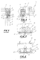
- the frame comprises drawn aluminum profiles 1, which are held together by angles 9 in the corner area.
- the aluminum profile 1, which can be seen in cross section in FIG. 2, has a C-shaped cross section.
- the horizontal incision serves to receive a holding plate 25.
- the vertical groove 13 provided in the lower leg of the profile 1 receives the upper edge, a pane 11 or another door panel.
- the running rail 5 can be attached to a cabinet ceiling 15 on the end face or to the underside of a cabinet or room ceiling 15 (cf. FIG. 4).
- the drive 7 includes a roller carrier 17 at least one pair of rollers 19 on the two Treads 21 laterally of the slot 23 in the Roller 5 can roll.
- the drive 7 further comprises the holding plate 25, which with the roller carrier 17 through a connecting means, for example by a screw 27 is connected.
- the screw 27 penetrates the Base body 29 of the holding plate 25 from below by a Guide bore 31 and is in the roller carrier 17 in one Threaded bore 33 out.
- the head 35 of the screw 27 lies in an at least one-sided accessible Recess 37 in the base body 29.
- the base body 29 of the holding plate 25 has in and is essentially a rectangular plan penetrated in the center by the guide bore 31. This ends at the upper surface 39 of the base body 29 in a centering part projecting above the surface 39 41, the two laterally perpendicular to the longitudinal edges of the Base body 29 has extending guide surfaces 43.
- the two guide surfaces 43 can, as in FIG. 3 represented, above by a guide rib or a Paragraph 45 must be completed. The function of paragraph 45 becomes closer to the second embodiment explained.
- resilient retaining cams 47 educated.
- the Holding plate 25 is made of plastic, are resilient retaining cams 47 by appropriate Shaping.
- the retention cams 47 are on Base body 29 through a horizontally lying incision 49 and a vertical cut 51 is generated.
- the cams 47 are in their increase in elasticity Root area 53 tapers.
- the free end of the Restraint cam 47 includes a stepped one at the top Retaining lug 55, at the front of which is essentially one Support surface 57 lying parallel to surface 39 located. The latter is preferably followed by one inclined pusher surface 59.
- the two retention cams 47 are advantageous, as shown in FIG. 3 is shown at the front by a pusher bar 61 connected with each other.
- the pusher bar 61 is in a short distance from the surface 39 of the Basic body 29.
- the recess 37 for the screw head 35 can Base body 29 completely or almost entirely horizontally penetrate.
- the side boundary walls 63 of the Recess 37 can be parallel or, as in the example in Figure 4 shown, acute to each other be trained.
- the holding plate 25 in the frame 1 or the Frame 1 forming profile 1 can be inserted, the latter essentially C-shaped, i.e. the profile 1 is open at the rear 65 of the sliding door 5.
- the upper leg 67 with a perpendicular to the edges of profile 1 Provide incision 81 of width B (see FIG. 5).
- the width B of the incision 81 is slightly larger than the distance b between the two guide surfaces 43 am Centering part 41 (see FIG. 3). In this incision 81 can now be inserted the holding plate 25.
- In the rear edge is fully inserted 69 of the base body 29 on the rear surface 71 of the Frame profile 1.
- the retaining tabs 55 latch behind a bead 73 on the upper leg of the profile 1 and keep the holding plate 25 immovable within the Profile 1 fixed.
- the two retaining cams 47 by light pressure on the pressure bar 61 synchronously led downward and out of the area of the cams 47 be solved.
- the holding plate 25 according to the invention can also be use on sliding doors that are not within a Cabinets are slidably arranged, rather than so-called Vorfrontten are curtain according to Figure 4.
- the Sliding door 3 a support bracket 75, e.g. with screws 77, attached.
- an incision 81 let in (see FIG. 6).
- the two guide edges 43 of the centering part 41 out and through the step 45 on the centering part 41 also in vertical direction.
- the retention lugs 55 reach under the bead, which is also on the angle plate 75 is formed, and hold the holding plate 25 non-detachably firmly.
Landscapes
- Engineering & Computer Science (AREA)
- Mechanical Engineering (AREA)
- Support Devices For Sliding Doors (AREA)
- Automobile Manufacture Line, Endless Track Vehicle, Trailer (AREA)
- Freezers Or Refrigerated Showcases (AREA)
- Power-Operated Mechanisms For Wings (AREA)
Applications Claiming Priority (2)
| Application Number | Priority Date | Filing Date | Title |
|---|---|---|---|
| CH1772000 | 2000-01-28 | ||
| CH177002000 | 2000-01-28 |
Publications (3)
| Publication Number | Publication Date |
|---|---|
| EP1120522A2 true EP1120522A2 (fr) | 2001-08-01 |
| EP1120522A3 EP1120522A3 (fr) | 2008-12-24 |
| EP1120522B1 EP1120522B1 (fr) | 2010-09-01 |
Family
ID=4427561
Family Applications (1)
| Application Number | Title | Priority Date | Filing Date |
|---|---|---|---|
| EP01810009A Expired - Lifetime EP1120522B1 (fr) | 2000-01-28 | 2001-01-05 | Chariot pour porte coulissante |
Country Status (3)
| Country | Link |
|---|---|
| EP (1) | EP1120522B1 (fr) |
| AT (1) | ATE479810T1 (fr) |
| DE (1) | DE50115608D1 (fr) |
Cited By (3)
| Publication number | Priority date | Publication date | Assignee | Title |
|---|---|---|---|---|
| US20100205772A1 (en) * | 2009-02-15 | 2010-08-19 | Hawa Ag | Carriage for a separation element, separation element and device |
| DE102010036730B4 (de) * | 2009-09-28 | 2014-05-15 | Werner Works Vertriebs Gmbh | Schrankmöbel |
| US9085924B2 (en) | 2012-12-04 | 2015-07-21 | Milgard Manufacturing Incorporated | Lift adjust sliding door roller |
Family Cites Families (3)
| Publication number | Priority date | Publication date | Assignee | Title |
|---|---|---|---|---|
| US2617141A (en) * | 1950-01-19 | 1952-11-11 | Sterling Hardware Mfg Co | Sliding door hanger assembly |
| US3959849A (en) * | 1975-08-08 | 1976-06-01 | Miller Industries, Inc. | Roller assembly for sliding doors |
| AU529262B2 (en) * | 1979-01-17 | 1983-06-02 | Milan Vucic | Suspension means for sliding doors |
-
2001
- 2001-01-05 AT AT01810009T patent/ATE479810T1/de not_active IP Right Cessation
- 2001-01-05 EP EP01810009A patent/EP1120522B1/fr not_active Expired - Lifetime
- 2001-01-05 DE DE50115608T patent/DE50115608D1/de not_active Expired - Lifetime
Cited By (4)
| Publication number | Priority date | Publication date | Assignee | Title |
|---|---|---|---|---|
| US20100205772A1 (en) * | 2009-02-15 | 2010-08-19 | Hawa Ag | Carriage for a separation element, separation element and device |
| US8381354B2 (en) * | 2009-02-15 | 2013-02-26 | Hawa Ag | Carriage for a separation element, separation element and device |
| DE102010036730B4 (de) * | 2009-09-28 | 2014-05-15 | Werner Works Vertriebs Gmbh | Schrankmöbel |
| US9085924B2 (en) | 2012-12-04 | 2015-07-21 | Milgard Manufacturing Incorporated | Lift adjust sliding door roller |
Also Published As
| Publication number | Publication date |
|---|---|
| EP1120522B1 (fr) | 2010-09-01 |
| ATE479810T1 (de) | 2010-09-15 |
| EP1120522A3 (fr) | 2008-12-24 |
| DE50115608D1 (de) | 2010-10-14 |
Similar Documents
| Publication | Publication Date | Title |
|---|---|---|
| DE10338816B3 (de) | Halterung für eine Platte, insbesondere für eine Glasscheibe | |
| DE69705662T2 (de) | Rollvorrichtung für Schiebetüren, Fenster oder ähnliches | |
| AT511683B1 (de) | Schublade | |
| DE19733367B4 (de) | Flügel für eine Tür, ein Fenster oder dergleichen | |
| EP2366857B1 (fr) | Agencement de fixation pour une porte coulissante | |
| EP0178598B1 (fr) | Ensemble de construction pour cadre de meuble réalisable individuellement tel que des vitrines de présentation, comptoirs de vente, mobilier d'exposition ou similaire | |
| DE3238204A1 (de) | Vorrichtung zur haengenden anbringung von scheiben an einer laufschiene | |
| EP1120522B1 (fr) | Chariot pour porte coulissante | |
| EP1486639B1 (fr) | Joint d'étanchéité descendant pour porte | |
| CH664678A5 (de) | Schubkastenauszug. | |
| AT402998B (de) | Schubladenausziehführung für rahmenmöbel | |
| DE20314821U1 (de) | Aufhängevorrichtung für einen Wandschrank | |
| AT399086B (de) | Verstellvorrichtung für schubladenblenden, insbesondere für küchenmöbelauszüge | |
| EP1124031A2 (fr) | Charnière, en particulier pour portes, fenêtres et similaires | |
| DE4014106C2 (de) | Bodendichtungsleiste für eine Drehflügeltür | |
| DE10323695B4 (de) | Schiebetürprofil | |
| EP2504513B1 (fr) | Chariot pour porte coulissante | |
| EP3805514B1 (fr) | Dispositif de fixation pour les dispositifs de protection de la lumière et/ou de la vue | |
| EP1460225A1 (fr) | Chariot pour une porte coulissante | |
| DE102005052600A1 (de) | Befestigungsclip für ein Tragprofil einer Verschattungsanlage | |
| DE102005032063B3 (de) | Beschlag zur Klemmbefestigung einer Glasscheibe | |
| EP1790816A2 (fr) | Joint descendant pour une porte sans seuil | |
| DE102004052283B3 (de) | Gleitschiene | |
| DE10209135A1 (de) | Laufwerkanordnung für Schiebetür | |
| DE102023122941A1 (de) | Freizeitfahrzeug, Schiebetür und Federelement für Schiebetüren von Freizeitfahrzeugen |
Legal Events
| Date | Code | Title | Description |
|---|---|---|---|
| PUAI | Public reference made under article 153(3) epc to a published international application that has entered the european phase |
Free format text: ORIGINAL CODE: 0009012 |
|
| AK | Designated contracting states |
Kind code of ref document: A2 Designated state(s): AT BE CH CY DE DK ES FI FR GB GR IE IT LI LU MC NL PT SE TR |
|
| AX | Request for extension of the european patent |
Free format text: AL;LT;LV;MK;RO;SI |
|
| PUAL | Search report despatched |
Free format text: ORIGINAL CODE: 0009013 |
|
| AK | Designated contracting states |
Kind code of ref document: A3 Designated state(s): AT BE CH CY DE DK ES FI FR GB GR IE IT LI LU MC NL PT SE TR |
|
| AX | Request for extension of the european patent |
Extension state: AL LT LV MK RO SI |
|
| 17P | Request for examination filed |
Effective date: 20090415 |
|
| 17Q | First examination report despatched |
Effective date: 20090730 |
|
| AKX | Designation fees paid |
Designated state(s): AT CH DE ES IT LI |
|
| GRAP | Despatch of communication of intention to grant a patent |
Free format text: ORIGINAL CODE: EPIDOSNIGR1 |
|
| GRAS | Grant fee paid |
Free format text: ORIGINAL CODE: EPIDOSNIGR3 |
|
| GRAA | (expected) grant |
Free format text: ORIGINAL CODE: 0009210 |
|
| AK | Designated contracting states |
Kind code of ref document: B1 Designated state(s): AT CH DE ES IT LI |
|
| REG | Reference to a national code |
Ref country code: CH Ref legal event code: EP |
|
| REF | Corresponds to: |
Ref document number: 50115608 Country of ref document: DE Date of ref document: 20101014 Kind code of ref document: P |
|
| REG | Reference to a national code |
Ref country code: CH Ref legal event code: NV Representative=s name: HANS RUDOLF GACHNANG PATENTANWALT |
|
| REG | Reference to a national code |
Ref country code: CH Ref legal event code: NV Representative=s name: GACHNANG AG PATENTANWAELTE |
|
| PGFP | Annual fee paid to national office [announced via postgrant information from national office to epo] |
Ref country code: CH Payment date: 20110114 Year of fee payment: 11 |
|
| PG25 | Lapsed in a contracting state [announced via postgrant information from national office to epo] |
Ref country code: ES Free format text: LAPSE BECAUSE OF FAILURE TO SUBMIT A TRANSLATION OF THE DESCRIPTION OR TO PAY THE FEE WITHIN THE PRESCRIBED TIME-LIMIT Effective date: 20101212 |
|
| PLBE | No opposition filed within time limit |
Free format text: ORIGINAL CODE: 0009261 |
|
| STAA | Information on the status of an ep patent application or granted ep patent |
Free format text: STATUS: NO OPPOSITION FILED WITHIN TIME LIMIT |
|
| 26N | No opposition filed |
Effective date: 20110606 |
|
| REG | Reference to a national code |
Ref country code: DE Ref legal event code: R097 Ref document number: 50115608 Country of ref document: DE Effective date: 20110606 |
|
| REG | Reference to a national code |
Ref country code: AT Ref legal event code: MM01 Ref document number: 479810 Country of ref document: AT Kind code of ref document: T Effective date: 20110105 |
|
| REG | Reference to a national code |
Ref country code: CH Ref legal event code: PL |
|
| PG25 | Lapsed in a contracting state [announced via postgrant information from national office to epo] |
Ref country code: LI Free format text: LAPSE BECAUSE OF NON-PAYMENT OF DUE FEES Effective date: 20120131 Ref country code: CH Free format text: LAPSE BECAUSE OF NON-PAYMENT OF DUE FEES Effective date: 20120131 |
|
| PG25 | Lapsed in a contracting state [announced via postgrant information from national office to epo] |
Ref country code: AT Free format text: LAPSE BECAUSE OF NON-PAYMENT OF DUE FEES Effective date: 20110105 |
|
| PGFP | Annual fee paid to national office [announced via postgrant information from national office to epo] |
Ref country code: IT Payment date: 20150129 Year of fee payment: 15 |
|
| PGFP | Annual fee paid to national office [announced via postgrant information from national office to epo] |
Ref country code: DE Payment date: 20160119 Year of fee payment: 16 |
|
| PG25 | Lapsed in a contracting state [announced via postgrant information from national office to epo] |
Ref country code: IT Free format text: LAPSE BECAUSE OF NON-PAYMENT OF DUE FEES Effective date: 20160105 |
|
| REG | Reference to a national code |
Ref country code: DE Ref legal event code: R082 Ref document number: 50115608 Country of ref document: DE Representative=s name: MAUCHER JENKINS, DE Ref country code: DE Ref legal event code: R082 Ref document number: 50115608 Country of ref document: DE Representative=s name: MAUCHER JENKINS PATENTANWAELTE & RECHTSANWAELT, DE Ref country code: DE Ref legal event code: R081 Ref document number: 50115608 Country of ref document: DE Owner name: HAWA SLIDING SOLUTIONS AG, CH Free format text: FORMER OWNER: EKU AG, SIRNACH, CH |
|
| REG | Reference to a national code |
Ref country code: DE Ref legal event code: R119 Ref document number: 50115608 Country of ref document: DE |
|
| PG25 | Lapsed in a contracting state [announced via postgrant information from national office to epo] |
Ref country code: DE Free format text: LAPSE BECAUSE OF NON-PAYMENT OF DUE FEES Effective date: 20170801 |