EP1120555A1 - Ein Verfahren und ein Ansaugluftsystem in einer Brennkraftmaschine - Google Patents
Ein Verfahren und ein Ansaugluftsystem in einer Brennkraftmaschine Download PDFInfo
- Publication number
- EP1120555A1 EP1120555A1 EP01200246A EP01200246A EP1120555A1 EP 1120555 A1 EP1120555 A1 EP 1120555A1 EP 01200246 A EP01200246 A EP 01200246A EP 01200246 A EP01200246 A EP 01200246A EP 1120555 A1 EP1120555 A1 EP 1120555A1
- Authority
- EP
- European Patent Office
- Prior art keywords
- air
- hollow body
- air manifold
- intake system
- manifold
- Prior art date
- Legal status (The legal status is an assumption and is not a legal conclusion. Google has not performed a legal analysis and makes no representation as to the accuracy of the status listed.)
- Granted
Links
- 238000002485 combustion reaction Methods 0.000 title claims abstract description 16
- 238000000034 method Methods 0.000 title claims abstract description 13
- 239000007789 gas Substances 0.000 description 9
- MWUXSHHQAYIFBG-UHFFFAOYSA-N nitrogen oxide Inorganic materials O=[N] MWUXSHHQAYIFBG-UHFFFAOYSA-N 0.000 description 9
- 230000001419 dependent effect Effects 0.000 description 3
- 230000004888 barrier function Effects 0.000 description 2
- 230000006835 compression Effects 0.000 description 2
- 238000007906 compression Methods 0.000 description 2
- 238000010276 construction Methods 0.000 description 2
- 230000000694 effects Effects 0.000 description 2
- 239000000446 fuel Substances 0.000 description 2
- 229910000831 Steel Inorganic materials 0.000 description 1
- 230000015572 biosynthetic process Effects 0.000 description 1
- 238000005266 casting Methods 0.000 description 1
- 230000007423 decrease Effects 0.000 description 1
- 238000006073 displacement reaction Methods 0.000 description 1
- 230000008030 elimination Effects 0.000 description 1
- 238000003379 elimination reaction Methods 0.000 description 1
- 238000004880 explosion Methods 0.000 description 1
- 239000002737 fuel gas Substances 0.000 description 1
- 239000000463 material Substances 0.000 description 1
- 238000005259 measurement Methods 0.000 description 1
- 239000002184 metal Substances 0.000 description 1
- 230000010363 phase shift Effects 0.000 description 1
- 230000029058 respiratory gaseous exchange Effects 0.000 description 1
- 239000000779 smoke Substances 0.000 description 1
- 239000010959 steel Substances 0.000 description 1
- 230000001052 transient effect Effects 0.000 description 1
- 238000003466 welding Methods 0.000 description 1
Images
Classifications
-
- F—MECHANICAL ENGINEERING; LIGHTING; HEATING; WEAPONS; BLASTING
- F02—COMBUSTION ENGINES; HOT-GAS OR COMBUSTION-PRODUCT ENGINE PLANTS
- F02B—INTERNAL-COMBUSTION PISTON ENGINES; COMBUSTION ENGINES IN GENERAL
- F02B27/00—Use of kinetic or wave energy of charge in induction systems, or of combustion residues in exhaust systems, for improving quantity of charge or for increasing removal of combustion residues
- F02B27/005—Oscillating pipes with charging achieved by arrangement, dimensions or shapes of intakes pipes or chambers; Ram air pipes
-
- F—MECHANICAL ENGINEERING; LIGHTING; HEATING; WEAPONS; BLASTING
- F02—COMBUSTION ENGINES; HOT-GAS OR COMBUSTION-PRODUCT ENGINE PLANTS
- F02B—INTERNAL-COMBUSTION PISTON ENGINES; COMBUSTION ENGINES IN GENERAL
- F02B29/00—Engines characterised by provision for charging or scavenging not provided for in groups F02B25/00, F02B27/00 or F02B33/00 - F02B39/00; Details thereof
- F02B29/04—Cooling of air intake supply
- F02B29/0406—Layout of the intake air cooling or coolant circuit
-
- F—MECHANICAL ENGINEERING; LIGHTING; HEATING; WEAPONS; BLASTING
- F02—COMBUSTION ENGINES; HOT-GAS OR COMBUSTION-PRODUCT ENGINE PLANTS
- F02B—INTERNAL-COMBUSTION PISTON ENGINES; COMBUSTION ENGINES IN GENERAL
- F02B33/00—Engines characterised by provision of pumps for charging or scavenging
- F02B33/44—Passages conducting the charge from the pump to the engine inlet, e.g. reservoirs
-
- Y—GENERAL TAGGING OF NEW TECHNOLOGICAL DEVELOPMENTS; GENERAL TAGGING OF CROSS-SECTIONAL TECHNOLOGIES SPANNING OVER SEVERAL SECTIONS OF THE IPC; TECHNICAL SUBJECTS COVERED BY FORMER USPC CROSS-REFERENCE ART COLLECTIONS [XRACs] AND DIGESTS
- Y02—TECHNOLOGIES OR APPLICATIONS FOR MITIGATION OR ADAPTATION AGAINST CLIMATE CHANGE
- Y02T—CLIMATE CHANGE MITIGATION TECHNOLOGIES RELATED TO TRANSPORTATION
- Y02T10/00—Road transport of goods or passengers
- Y02T10/10—Internal combustion engine [ICE] based vehicles
- Y02T10/12—Improving ICE efficiencies
Definitions
- the present invention relates to a process to reduce pressure in an air intake system in a turbocharged combustion engine, in which a turbocharger supplies air via a charge air cooler to an air manifold and an air intake system in a combustion engine, such as diesel and/or gas engines, comprising a turbocharger and a charge air cooler connected to an air manifold adjacent to or incorporated in the engine.
- the air filling sequence of the cylinders can cause standing pressure waves in the air column of the air manifold, which can result in differences in the air supply from cylinder to cylinder and hence different compression pressure and maximum pressure. This can affect the output of an engine in many ways.
- the formation of nitrogen oxides (NO x ) in a combustion engine increases with increasing combustion temperature.
- International standards set maximum permissible levels of NO x in the exhaust gas, consequently the consideration for low NO x emission is weighed against the consideration for high fuel efficiency.
- uneven cylinder-to-cylinder air supply can cause increased smoke emissions as a consequence of reduced air filling in some of the cylinders.
- US Patent 4,625,686 and US Patent 4,513,699 discloses different solutions for application of a resonance pipe in an air intake system.
- the aims of the aforementioned patent documents are different from what is achieved with the present invention and they also describe solutions that cannot overcome the disadvantages mentioned above, in that their designs differ considerably from the present invention.
- the resonance pipes are open at both ends and the charge air is fed through the pipes, something which leads to a dynamic pressure increase in the air intake system thus increasing engine power.
- US Patent 4,625,686 discloses an air intake system for a six cylinder engine in which at least one resonance tank is of a length sufficient to cover all inlets of the cylinders, and where the air supply from the turbo-charger is supplied through the resonance pipes through a supply vessel in the form of a cover.
- One of the objects of the invention is to provide extra boost, i.e. an increase in the charge air pressure to the cylinders by means of the integrated resonance pipe in the inlet to the air intake.
- US Patent 4,513,699 disclose a system to reduce the size of the air intake system of a combustion engine, because of the limited space which is available under the hood of a vehicle, in which the cross-section of the resonance pipe decreases in the longitudinal direction, from at least the pipe end which adjoins a resonance chamber, and in which the resonance chamber is arranged to adjoin the cylinders of the engine.
- the object of the present invention is to eliminate the disadvantages which are mentioned previously and also to reduce or to counteract undesired pressure swings in the air manifold in a combustion engine, preferably diesel and gas engines, with a construction that is as simple and compact as possible and with the smallest possible change in the volume of the air manifold.
- This object is achieved, according to the present invention, in that a starting point is assumed based on that there is a standing pressure wave with a given frequency, which is associated with the operating speed of the engine.
- the harmonic pressure and mass flow fluctuations have a phase shift of 90 degrees and the pressure fluctuation will peak at the closed end of the air manifold, in which the mass flow can not be anything else but zero. By changing these conditions at the end of the air manifold, the fluctuations will be affected.
- the process according to the present invention is characterised in that an substantially elongated hollow body, adapted to influence pressure fluctuations in the air manifold, is being arranged in or at the manifold, and where the hollow body is providing a fluctuating air flow which is large enough to counteract a pressure fluctuation in the air manifold.
- the one end of the hollow body can be closed and the other open end is arranged at the closed end of the air manifold at a distance corresponding to between approximately a half and five times, preferably one time, the effective diameter of the body, and the length of the hollow body can be determined by the pressure wave frequency of the air in the body and the actual speed of sound in the air.
- the air intake system according to the present invention is characterised in that an elongated hollow body which is adapted to reduce pressure fluctuations in the air manifold, is arranged in or at the air manifold, and where the hollow body comprises a first end which is closed, in or at the end, and which is fully or partly open in its other end.
- the elongated hollow body comprises a pipe shaped body or a pipe, where the open end is arranged at the closed end of the air manifold, and that the open end of the hollow body is arranged at a distance from the closed end of the air manifold corresponding to between approximately a half and five times, preferably one time, the effective diameter of the body.
- the substantially elongated hollow body is arranged longitudinally inside the air manifold, or adjacent to the air manifold or integrated in the air manifold, and that the hollow body comprises an adjustable piston arranged at one end of the body.
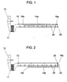
- Figure 1 shows an air intake system comprising an example of a preferred embodiment of the device, according to the present invention, arranged inside an air manifold.
- Figure 2 shows the device corresponding to Figure 1, according to the invention, arranged adjacent to the manifold.
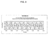
- FIG. 3 shows schematically pressure waves at the end of an air manifold, measured during test trials of the present invention.
- Turbo-charged medium speed diesel and gas engines normally have the turbocharger(s) mounted at the end of the engine frame.
- the air from the compressor 10 of the turbocharger is fed through a charge air cooler 11 and into an air manifold 12 which runs along the engine and is connected to the individual intake ports of the cylinders (two of the intake ports are shown by reference number 24), which is well known to one skilled in the art.
- the air manifold can be formed as an extended body or vessel, flanged onto the engine, often with one per cylinder block in a V-type engine.
- the air manifold can also be an integrated volume in the engine frame, and for this solution it is normal that the cylinder banks on a V-type engine share a common volume.
- Figure 1 shows a section of an air intake system comprising an air manifold 12 in which an example of a preferred embodiment of the device, according to the present invention, is arranged inside the air manifold 12.
- a substantially elongated hollow body 14a is arranged in the air manifold, comprising a first end 16a which is closed and a second end 18a which is open and in which the open end 18a is arranged at the closed end 20 of the air manifold.
- the hollow body 14a When a standing pressure wave in the air manifold 12 arises, the hollow body 14a is excited to provide a movement of air, i.e. an oscillating air flow large enough to counteract the pressure waves in the air manifold 12 is set up.
- This can be a passive system, the resonant frequency of which is adjusted to coincide with the frequency of the unwanted pressure waves.
- the present invention an almost total elimination of the unwanted pressure waves is obtained.
- a solution such as this is also a very compact construction.
- Figure 2 shows a corresponding substantially elongated hollow body 14b arranged on the outside of the air manifold 12.
- the hollow body 14b can be arranged on the outside of the air manifold 12 and comprises, corresponding to the first embodiment, a first closed end 16b and a second open end 18b which is arranged at the closed end of the air manifold 20.
- the hollow body 14b can be arranged alongside the air manifold 12 and can then, for example, comprise an curved part 22 at the second open end 18b.
- Other possibilities for placing the hollow body are of course also possible.
- the arrangement of the hollow body is dependent on the shape of the air manifold and the engine, and of course, also space consideration in the air manifold.
- the hollow body 14a, 14b can be closed at one end by means of a barrier, such as for example, a cover that is mounted in or at the end which is to be closed or by means of, for example, an adjustable piston.
- a barrier such as for example, a cover that is mounted in or at the end which is to be closed or by means of, for example, an adjustable piston.
- the hollow body can also be made in an otherwise known way with such a barrier integrated in or at the one end.
- the hollow body can also be an integrated part of the air manifold itself when this is manufactured as, for example, a casting (not shown).
- the hollow body (14a, 14b) can be fitted to the air manifold in a known way, such as for example, by welding fastening points onto the body for connection in or to the air manifold by means of screws/bolts, or it can be welded in or to the air manifold, or in another way secured permanently, or in a removable fashion, in or to the air manifold.
- the hollow body can comprise a movable piston arranged inside the hollow body (not shown). This piston can be moved, and be used to fine-tune the resonance frequency of the hollow body. As the pressure amplitude in the hollow body is much larger than the original pressure amplitude in the air manifold, the volume of the hollow body can be much smaller than the volume of the air manifold.
- the air column will fluctuate with a displacement node at the closed end of the body, and with a pressure node at the open end.
- the mode shape of the first resonance frequency will have the form of a quarter wave, that is, the wavelength that corresponds to the frequency of the form of the first resonance frequency is four times the length of the hollow body.
- Such a body in which the first resonance frequency of the air-column in the pipe corresponds to the frequency of the unwanted pressure waves in the air manifold, is a very effective resonator when it is arranged with its open end connected to the closed end of the air manifold.
- the length of the hollow body is determined by the wave frequency and the actual speed of sound of the air, which again is given by the air temperature.
- the volume decides its "breathing capacity", that is there must be an expedient relationship between length and diameter.
- Figure 3 shows schematically pressure swings at the end of an air manifold, in which the two graphs show pressure swings with and without the device respectively according to the present invention.
- the full line shows the standing pressure waves in the air manifold without the hollow body, measured at 75% load and at the end cover of the air manifold.
- the pressure fluctuates with double amplitude up towards 0.45 bars.
- this can cause standing pressure waves in the air-column in the air manifold, which in turn, can result in uneven cylinder-to-cylinder air filling and hence uneven compression pressures and maximum cylinder pressures. This will have a negative effect on the output of the engine.
- the dotted line shows the pressure swings in the air manifold with the hollow body measured at 85% load and at the end cover of the air manifold.
- the obvious standing wave form is no longer present, or is distinctly reduced.
- the pressure fluctuates in this case with significantly reduced double amplitude of 0.15 bars, and the swing phenomenon is dominated by higher order modes and noise. As the numbers show, 0.15 bars in comparison with 0.45 bars, reduces the amplitude with between 60% and 70%.
- the present invention provides a particularly suitable process to reduce pressure waves in an air intake system of a combustion engine, and a corresponding device at an air intake system of a combustion engine.
- the process and device can be used in all combustion engines with an air intake system comprising an air manifold, but is preferably used in diesel and gas engines, and particularly preferred in gas engines with 9 or 18 cylinders. It is also dependent on the number of revolutions and if it is a four or two stroke engine.
- a hollow body such as a pipe-shaped resonator, will in most cases be very simple to fit to an engine, and occupy little space.
- the pipe can be arranged inside the air manifold.
- the pipe is arranged such that the open end of the pipe, for example, is arranged at a distance equal to its effective diameter from the end of the air manifold. If this is not possible, the pipe can for example, be arranged on the outside of the engine, with connections to the air manifold at the end of this.
- the hollow body can, for example, be made of standard pipes in steel, metal or other materials, and does not need to have a perfectly circular cross-section that is constant along the pipe, but can also include other geometrical cross-sections which are suitable to provide the same characteristics and which can vary along the pipe. The same is the case if the hollow body is arranged on the outside on the engine.
Landscapes
- Engineering & Computer Science (AREA)
- Chemical & Material Sciences (AREA)
- Combustion & Propulsion (AREA)
- Mechanical Engineering (AREA)
- General Engineering & Computer Science (AREA)
- Physics & Mathematics (AREA)
- Thermal Sciences (AREA)
- Characterised By The Charging Evacuation (AREA)
- Cylinder Crankcases Of Internal Combustion Engines (AREA)
- Output Control And Ontrol Of Special Type Engine (AREA)
- Valve Device For Special Equipments (AREA)
- Exhaust Gas After Treatment (AREA)
Applications Claiming Priority (2)
| Application Number | Priority Date | Filing Date | Title |
|---|---|---|---|
| NO20000338 | 2000-01-24 | ||
| NO20000338A NO310842B1 (no) | 2000-01-24 | 2000-01-24 | Fremgangsmåte og anordning ved drift av en forbrenningsmotor |
Publications (2)
| Publication Number | Publication Date |
|---|---|
| EP1120555A1 true EP1120555A1 (de) | 2001-08-01 |
| EP1120555B1 EP1120555B1 (de) | 2003-05-07 |
Family
ID=19910630
Family Applications (1)
| Application Number | Title | Priority Date | Filing Date |
|---|---|---|---|
| EP01200246A Expired - Lifetime EP1120555B1 (de) | 2000-01-24 | 2001-01-24 | Ein Verfahren und ein Ansaugluftsystem in einer Brennkraftmaschine |
Country Status (7)
| Country | Link |
|---|---|
| EP (1) | EP1120555B1 (de) |
| AT (1) | ATE239864T1 (de) |
| DE (1) | DE60100234T2 (de) |
| DK (1) | DK1120555T3 (de) |
| ES (1) | ES2199201T3 (de) |
| HK (1) | HK1039362A1 (de) |
| NO (1) | NO310842B1 (de) |
Cited By (1)
| Publication number | Priority date | Publication date | Assignee | Title |
|---|---|---|---|---|
| US6622486B2 (en) | 2000-11-08 | 2003-09-23 | Wartsila Technology Oy Ab | Arrangement for and method of feeding air in a piston engine |
Families Citing this family (2)
| Publication number | Priority date | Publication date | Assignee | Title |
|---|---|---|---|---|
| DE102007052310A1 (de) * | 2007-10-31 | 2009-05-07 | Dr. Ing. H.C. F. Porsche Aktiengesellschaft | Brennkraftmaschine |
| EP2017447B1 (de) | 2007-07-16 | 2019-12-04 | Dr. Ing. h.c. F. Porsche AG | Brennkraftmaschine |
Citations (5)
| Publication number | Priority date | Publication date | Assignee | Title |
|---|---|---|---|---|
| GB2026091A (en) * | 1978-07-20 | 1980-01-30 | Saurer Ag Adolph | Method and apparatus for the pressure-charging of a multiple- cylinder reciprocating engine |
| US4513699A (en) | 1983-02-22 | 1985-04-30 | Autoipari Kutato Es Fejleszto Vallalat | Intake gas resonance system for internal combustion engines |
| US4625686A (en) | 1983-12-13 | 1986-12-02 | M.A.N. Maschinenfabrik Augsburg-Nurnberg Aktiengesellschaft | Compact fresh-gas intake system for engines with combination supercharging |
| DE3908475A1 (de) * | 1988-03-15 | 1989-09-28 | Mazda Motor | Ansaugsystem fuer eine aufgeladene brennkraftmaschine |
| US5031598A (en) * | 1988-03-15 | 1991-07-16 | Mazda Motor Corporation | Intake system for multi-cylinder engine with supercharger |
-
2000
- 2000-01-24 NO NO20000338A patent/NO310842B1/no not_active IP Right Cessation
-
2001
- 2001-01-24 DE DE60100234T patent/DE60100234T2/de not_active Expired - Lifetime
- 2001-01-24 DK DK01200246T patent/DK1120555T3/da active
- 2001-01-24 ES ES01200246T patent/ES2199201T3/es not_active Expired - Lifetime
- 2001-01-24 AT AT01200246T patent/ATE239864T1/de active
- 2001-01-24 EP EP01200246A patent/EP1120555B1/de not_active Expired - Lifetime
-
2002
- 2002-02-01 HK HK02100778.6A patent/HK1039362A1/en unknown
Patent Citations (5)
| Publication number | Priority date | Publication date | Assignee | Title |
|---|---|---|---|---|
| GB2026091A (en) * | 1978-07-20 | 1980-01-30 | Saurer Ag Adolph | Method and apparatus for the pressure-charging of a multiple- cylinder reciprocating engine |
| US4513699A (en) | 1983-02-22 | 1985-04-30 | Autoipari Kutato Es Fejleszto Vallalat | Intake gas resonance system for internal combustion engines |
| US4625686A (en) | 1983-12-13 | 1986-12-02 | M.A.N. Maschinenfabrik Augsburg-Nurnberg Aktiengesellschaft | Compact fresh-gas intake system for engines with combination supercharging |
| DE3908475A1 (de) * | 1988-03-15 | 1989-09-28 | Mazda Motor | Ansaugsystem fuer eine aufgeladene brennkraftmaschine |
| US5031598A (en) * | 1988-03-15 | 1991-07-16 | Mazda Motor Corporation | Intake system for multi-cylinder engine with supercharger |
Cited By (1)
| Publication number | Priority date | Publication date | Assignee | Title |
|---|---|---|---|---|
| US6622486B2 (en) | 2000-11-08 | 2003-09-23 | Wartsila Technology Oy Ab | Arrangement for and method of feeding air in a piston engine |
Also Published As
| Publication number | Publication date |
|---|---|
| ES2199201T3 (es) | 2004-02-16 |
| NO20000338D0 (no) | 2000-01-24 |
| EP1120555B1 (de) | 2003-05-07 |
| DE60100234T2 (de) | 2004-02-19 |
| DK1120555T3 (da) | 2003-09-01 |
| HK1039362A1 (en) | 2002-04-19 |
| ATE239864T1 (de) | 2003-05-15 |
| NO20000338L (no) | 2001-07-25 |
| DE60100234D1 (de) | 2003-06-12 |
| NO310842B1 (no) | 2001-09-03 |
Similar Documents
| Publication | Publication Date | Title |
|---|---|---|
| KR950000600B1 (ko) | 과급기 부착엔진 | |
| US6814060B1 (en) | Engine emission control system and method | |
| US7210449B2 (en) | Method for controlling an internal combustion engine operating with direct fuel injection | |
| JP5315342B2 (ja) | 内燃機関 | |
| US4064696A (en) | Live-gas conduit system for turbocharged six-cylinder engines | |
| US5782226A (en) | Method of reducing the harmful emissions of a multicylinder internal combustion engine | |
| EP1120555B1 (de) | Ein Verfahren und ein Ansaugluftsystem in einer Brennkraftmaschine | |
| JP2007315680A (ja) | 熱音響スターリングエンジン | |
| GB2026091A (en) | Method and apparatus for the pressure-charging of a multiple- cylinder reciprocating engine | |
| US5746172A (en) | Process for increasing the torque of an internal combustion engine and internal combustion engine | |
| JPH06193480A (ja) | 水素エンジンの燃料供給装置 | |
| WO2024176039A1 (en) | Engine with resonator on the exhaust pipe and vehicle comprising said engine | |
| US7866147B2 (en) | Side branch absorber for exhaust manifold of two-stroke internal combustion engine | |
| US6282898B1 (en) | Operation of forced induction internal combustion engines | |
| JP2992968B2 (ja) | エンジン | |
| US11428131B2 (en) | Exhaust-gas aftertreatment arrangement | |
| CN112796872B (zh) | 一种谐振进气的柴油机系统 | |
| EP3653852A1 (de) | Abgasaufnahmeanordnung für einen grossen zweitaktmotor und grosser zweitaktmotor | |
| JP5780943B2 (ja) | 着火制御装置 | |
| Migaud et al. | A New Fast Method Combining Testing and Gas Exchange Simulations Applied to an Innovative Product Aimed to Increase Low-End Torque on Highly Downsized Engines | |
| KR950002627B1 (ko) | 내연기관의 활성화 가스 공급장치 | |
| JPH02259217A (ja) | エンジンの排気装置 | |
| Cui et al. | Turbocharging system design and performance analysis of a marine diesel engine | |
| Trenc et al. | Influence of the exhaust system on performance of a 4-cylinder supercharged engine | |
| Alt et al. | Investigation on order generation in the orifice noise of internal combustion engines |
Legal Events
| Date | Code | Title | Description |
|---|---|---|---|
| PUAI | Public reference made under article 153(3) epc to a published international application that has entered the european phase |
Free format text: ORIGINAL CODE: 0009012 |
|
| AK | Designated contracting states |
Kind code of ref document: A1 Designated state(s): AT BE CH CY DE DK ES FI FR GB GR IE IT LI LU MC NL PT SE TR |
|
| AX | Request for extension of the european patent |
Free format text: AL;LT;LV;MK;RO;SI |
|
| 17P | Request for examination filed |
Effective date: 20020131 |
|
| AKX | Designation fees paid |
Free format text: AT BE CH CY DE DK ES FI FR GB GR IE IT LI LU MC NL PT SE TR |
|
| AXX | Extension fees paid |
Free format text: AL PAYMENT 20020131;LT PAYMENT 20020131;LV PAYMENT 20020131;MK PAYMENT 20020131;RO PAYMENT 20020131 |
|
| 17Q | First examination report despatched |
Effective date: 20020318 |
|
| RAX | Requested extension states of the european patent have changed |
Free format text: AL PAYMENT 20020131;LT PAYMENT 20020131;LV PAYMENT 20020131;MK PAYMENT 20020131;RO PAYMENT 20020131;SI PAYMENT 20020131 |
|
| GRAH | Despatch of communication of intention to grant a patent |
Free format text: ORIGINAL CODE: EPIDOS IGRA |
|
| GRAH | Despatch of communication of intention to grant a patent |
Free format text: ORIGINAL CODE: EPIDOS IGRA |
|
| GRAA | (expected) grant |
Free format text: ORIGINAL CODE: 0009210 |
|
| AK | Designated contracting states |
Designated state(s): AT BE CH CY DE DK ES FI FR GB GR IE IT LI LU MC NL PT SE TR |
|
| AX | Request for extension of the european patent |
Extension state: AL LT LV MK RO SI |
|
| PG25 | Lapsed in a contracting state [announced via postgrant information from national office to epo] |
Ref country code: CY Free format text: LAPSE BECAUSE OF FAILURE TO SUBMIT A TRANSLATION OF THE DESCRIPTION OR TO PAY THE FEE WITHIN THE PRESCRIBED TIME-LIMIT Effective date: 20030507 Ref country code: LI Free format text: LAPSE BECAUSE OF FAILURE TO SUBMIT A TRANSLATION OF THE DESCRIPTION OR TO PAY THE FEE WITHIN THE PRESCRIBED TIME-LIMIT Effective date: 20030507 Ref country code: NL Free format text: LAPSE BECAUSE OF FAILURE TO SUBMIT A TRANSLATION OF THE DESCRIPTION OR TO PAY THE FEE WITHIN THE PRESCRIBED TIME-LIMIT Effective date: 20030507 Ref country code: CH Free format text: LAPSE BECAUSE OF FAILURE TO SUBMIT A TRANSLATION OF THE DESCRIPTION OR TO PAY THE FEE WITHIN THE PRESCRIBED TIME-LIMIT Effective date: 20030507 Ref country code: BE Free format text: LAPSE BECAUSE OF FAILURE TO SUBMIT A TRANSLATION OF THE DESCRIPTION OR TO PAY THE FEE WITHIN THE PRESCRIBED TIME-LIMIT Effective date: 20030507 |
|
| REG | Reference to a national code |
Ref country code: GB Ref legal event code: FG4D |
|
| REG | Reference to a national code |
Ref country code: CH Ref legal event code: EP |
|
| REG | Reference to a national code |
Ref country code: IE Ref legal event code: FG4D |
|
| REF | Corresponds to: |
Ref document number: 60100234 Country of ref document: DE Date of ref document: 20030612 Kind code of ref document: P |
|
| PG25 | Lapsed in a contracting state [announced via postgrant information from national office to epo] |
Ref country code: GR Free format text: LAPSE BECAUSE OF FAILURE TO SUBMIT A TRANSLATION OF THE DESCRIPTION OR TO PAY THE FEE WITHIN THE PRESCRIBED TIME-LIMIT Effective date: 20030807 Ref country code: PT Free format text: LAPSE BECAUSE OF FAILURE TO SUBMIT A TRANSLATION OF THE DESCRIPTION OR TO PAY THE FEE WITHIN THE PRESCRIBED TIME-LIMIT Effective date: 20030807 Ref country code: SE Free format text: LAPSE BECAUSE OF FAILURE TO SUBMIT A TRANSLATION OF THE DESCRIPTION OR TO PAY THE FEE WITHIN THE PRESCRIBED TIME-LIMIT Effective date: 20030807 |
|
| REG | Reference to a national code |
Ref country code: DK Ref legal event code: T3 |
|
| NLV1 | Nl: lapsed or annulled due to failure to fulfill the requirements of art. 29p and 29m of the patents act | ||
| LTIE | Lt: invalidation of european patent or patent extension |
Effective date: 20030507 |
|
| REG | Reference to a national code |
Ref country code: CH Ref legal event code: PL |
|
| PG25 | Lapsed in a contracting state [announced via postgrant information from national office to epo] |
Ref country code: LU Free format text: LAPSE BECAUSE OF NON-PAYMENT OF DUE FEES Effective date: 20040124 |
|
| PG25 | Lapsed in a contracting state [announced via postgrant information from national office to epo] |
Ref country code: IE Free format text: LAPSE BECAUSE OF NON-PAYMENT OF DUE FEES Effective date: 20040126 |
|
| PG25 | Lapsed in a contracting state [announced via postgrant information from national office to epo] |
Ref country code: MC Free format text: LAPSE BECAUSE OF NON-PAYMENT OF DUE FEES Effective date: 20040131 |
|
| REG | Reference to a national code |
Ref country code: ES Ref legal event code: FG2A Ref document number: 2199201 Country of ref document: ES Kind code of ref document: T3 |
|
| PLBE | No opposition filed within time limit |
Free format text: ORIGINAL CODE: 0009261 |
|
| STAA | Information on the status of an ep patent application or granted ep patent |
Free format text: STATUS: NO OPPOSITION FILED WITHIN TIME LIMIT |
|
| ET | Fr: translation filed | ||
| 26N | No opposition filed |
Effective date: 20040210 |
|
| REG | Reference to a national code |
Ref country code: IE Ref legal event code: MM4A |
|
| REG | Reference to a national code |
Ref country code: HK Ref legal event code: WD Ref document number: 1039362 Country of ref document: HK |
|
| REG | Reference to a national code |
Ref country code: FR Ref legal event code: PLFP Year of fee payment: 16 |
|
| REG | Reference to a national code |
Ref country code: DE Ref legal event code: R082 Ref document number: 60100234 Country of ref document: DE Representative=s name: KASTEL PATENTANWAELTE, DE Ref country code: DE Ref legal event code: R082 Ref document number: 60100234 Country of ref document: DE Representative=s name: KASTEL PATENTANWAELTE PARTG MBB, DE |
|
| REG | Reference to a national code |
Ref country code: FR Ref legal event code: PLFP Year of fee payment: 17 |
|
| REG | Reference to a national code |
Ref country code: FR Ref legal event code: PLFP Year of fee payment: 18 |
|
| PGFP | Annual fee paid to national office [announced via postgrant information from national office to epo] |
Ref country code: DE Payment date: 20200129 Year of fee payment: 20 Ref country code: DK Payment date: 20200129 Year of fee payment: 20 Ref country code: AT Payment date: 20200102 Year of fee payment: 20 Ref country code: GB Payment date: 20200127 Year of fee payment: 20 Ref country code: IT Payment date: 20200123 Year of fee payment: 20 Ref country code: ES Payment date: 20200205 Year of fee payment: 20 Ref country code: FI Payment date: 20200130 Year of fee payment: 20 |
|
| PGFP | Annual fee paid to national office [announced via postgrant information from national office to epo] |
Ref country code: FR Payment date: 20200127 Year of fee payment: 20 Ref country code: TR Payment date: 20200114 Year of fee payment: 20 |
|
| REG | Reference to a national code |
Ref country code: DE Ref legal event code: R071 Ref document number: 60100234 Country of ref document: DE |
|
| REG | Reference to a national code |
Ref country code: DK Ref legal event code: EUP Expiry date: 20210124 |
|
| REG | Reference to a national code |
Ref country code: GB Ref legal event code: PE20 Expiry date: 20210123 |
|
| REG | Reference to a national code |
Ref country code: FI Ref legal event code: MAE |
|
| REG | Reference to a national code |
Ref country code: AT Ref legal event code: MK07 Ref document number: 239864 Country of ref document: AT Kind code of ref document: T Effective date: 20210124 |
|
| PG25 | Lapsed in a contracting state [announced via postgrant information from national office to epo] |
Ref country code: GB Free format text: LAPSE BECAUSE OF EXPIRATION OF PROTECTION Effective date: 20210123 |
|
| REG | Reference to a national code |
Ref country code: ES Ref legal event code: FD2A Effective date: 20211230 |
|
| PG25 | Lapsed in a contracting state [announced via postgrant information from national office to epo] |
Ref country code: ES Free format text: LAPSE BECAUSE OF EXPIRATION OF PROTECTION Effective date: 20210125 |