EP1120575A2 - Strömungsgleichrichter - Google Patents
Strömungsgleichrichter Download PDFInfo
- Publication number
- EP1120575A2 EP1120575A2 EP01100470A EP01100470A EP1120575A2 EP 1120575 A2 EP1120575 A2 EP 1120575A2 EP 01100470 A EP01100470 A EP 01100470A EP 01100470 A EP01100470 A EP 01100470A EP 1120575 A2 EP1120575 A2 EP 1120575A2
- Authority
- EP
- European Patent Office
- Prior art keywords
- flow
- section
- designed
- rectifier according
- openings
- Prior art date
- Legal status (The legal status is an assumption and is not a legal conclusion. Google has not performed a legal analysis and makes no representation as to the accuracy of the status listed.)
- Granted
Links
- 238000011144 upstream manufacturing Methods 0.000 claims description 2
- 230000002457 bidirectional effect Effects 0.000 description 8
- 239000012530 fluid Substances 0.000 description 2
- 238000005259 measurement Methods 0.000 description 2
- 238000011161 development Methods 0.000 description 1
- 230000018109 developmental process Effects 0.000 description 1
Images

Classifications
-
- G—PHYSICS
- G01—MEASURING; TESTING
- G01F—MEASURING VOLUME, VOLUME FLOW, MASS FLOW OR LIQUID LEVEL; METERING BY VOLUME
- G01F1/00—Measuring the volume flow or mass flow of fluid or fluent solid material wherein the fluid passes through a meter in a continuous flow
- G01F1/66—Measuring the volume flow or mass flow of fluid or fluent solid material wherein the fluid passes through a meter in a continuous flow by measuring frequency, phase shift or propagation time of electromagnetic or other waves, e.g. using ultrasonic flowmeters
- G01F1/662—Constructional details
-
- F—MECHANICAL ENGINEERING; LIGHTING; HEATING; WEAPONS; BLASTING
- F15—FLUID-PRESSURE ACTUATORS; HYDRAULICS OR PNEUMATICS IN GENERAL
- F15D—FLUID DYNAMICS, i.e. METHODS OR MEANS FOR INFLUENCING THE FLOW OF GASES OR LIQUIDS
- F15D1/00—Influencing flow of fluids
- F15D1/02—Influencing flow of fluids in pipes or conduits
Definitions
- the invention relates to a flow straightener for rectifying a Fluid flow in a pipeline in which there is at least one measuring device, with a rectifying element that has a plurality of openings.
- the measuring device can be a flow meter, for example a turbine wheel meter, a vortex meter, an orifice plate or an ultrasonic measuring device act.
- Perforated plate rectifiers are known from practice, in particular Reduce the deformations of the axial speed profile.
- the Rectifier element is designed as a perforated plate, the Bore diameter and the arrangement of the bores very different could be.
- the design of the perforated plate in Dependence on the tolerable pressure loss and the characteristics of the disturbed flow profile selected.
- rectifiers In the case of swirling flow, rectifiers have proven themselves in practice, whose rectifying element is designed as a tube bundle. Such rectifiers can swirl the flow very effectively with a relatively low pressure drop dismantle. The deformations of the axial velocity profile are against it poorly broken down.
- Bidirectional measuring sections are measuring sections in which the Flow direction changes from time to time or where it is foreseeable that in a flow change will take place in the future.
- the measuring device In the case of a bidirectional measuring section using flow straighteners the measuring device is between two flow straighteners, and in a symmetrical arrangement. For security reasons, two can measuring devices connected in series can be used.
- the object of the invention is accordingly a generic Improve rectifiers so that when used in a bidirectional Measuring section the noise is avoided.
- the task is in a flow straightener of the type mentioned solved by the characterizing part of claim 1.
- a locking device is preferably assigned to at least one opening, which opens in one direction when there is an inflow and when the flow direction is reversed closes.
- An advantageous embodiment of the invention is that the locking device is designed as a check valve.
- the locking device as a ball locking device to train.
- the rectifying element can advantageously be used as a perforated plate or as a tube bundle be trained.
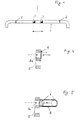
- 1 shows a measuring section 1, in which between two flow rectifiers 2 two measuring devices 3 connected in series in the form of ultrasonic counters are arranged. It is a bidirectional measuring section that both can be flowed through in one direction as well as in the other. In which each upstream flow straightener is part of the openings closed, while the downstream flow straightener the maximum flow cross-section is released.
- Fig. 2 shows a rectifier element 4, which has a plurality of evenly across has the cross-section distributed openings 5. The maximum flow area is released when all openings are flowed through.
- each opening 5a with a Locking device 6 is provided in the form of a check valve, which at Inflow closes in one direction and opens in the opposite direction.
- the openings 5a are with closing devices 6 provided in the form of ball closing devices.
- a ball 7 is movable arranged in a fluid-continuous cage 8 and closes depending on Flow direction the opening 5a.
Landscapes
- Physics & Mathematics (AREA)
- Engineering & Computer Science (AREA)
- Fluid Mechanics (AREA)
- Mechanical Engineering (AREA)
- General Engineering & Computer Science (AREA)
- Electromagnetism (AREA)
- General Physics & Mathematics (AREA)
- Measuring Volume Flow (AREA)
- Details Of Flowmeters (AREA)
- Rectifiers (AREA)
Abstract
Description
Claims (7)
- Strömungsgleichrichter zum Gleichrichten einer Strömung in einer Rohrleitung (1), in der sich mindestens ein Meßgerät (3) befindet, mit einem Gleichrichtelement (4), das eine Vielzahl von Öffnungen (5) aufweist, die einen freien Durchströmquerschnitt bilden,
dadurch gekennzeichnet, daß sich der freie Durchströmquerschnitt bei Umkehr der Strömungsrichtung ändert. - Strömungsgleichrichter nach Anspruch 1,
dadurch gekennzeichnet, daß mindestens einer Öffnung (5) eine Schließvorrichtung (6) zugeordnet ist, die bei Anströmung in eine Richtung öffnet und bei Umkehr der Strömungsrichtung schließt. - Strömungsgleichrichter nach Anspruch 2,
dadurch gekennzeichnet, daß die Schließvorrichtung (6) als Rückschlagklappe ausgebildet ist. - Strömungsgleichrichter nach Anspruch 2,
dadurch gekennzeichnet, daß die Schließvorrichtung (6) als Kugelschließvorrichtung ausgebildet ist. - Strömungsgleichrichter nach einem der Ansprüche 1 bis 4,
dadurch gekennzeichnet, daß das Gleichrichtelement (4) als Lochplatte ausgebildet ist. - Strömungsgleichrichter nach einem der Ansprüche 1 bis 4,
dadurch gekennzeichnet, daß das Gleichrichtelement (4) als Rohrbündel ausgebildet ist. - Anordnung von zwei Strömungsgleichrichtern zwischen denen mindestens ein Meßgerät (3) angeordnet ist
dadurch gekennzeichnet, daß bei dem jeweils stromaufliegenden Strömungsgleichrichter der-Durchströmquerschnitt teilweise verschlossen ist und daß bei dem jeweils stromabliegenden Strömungsgleichrichter der maximale Durchströmquerschnitt freigegeben ist.
Applications Claiming Priority (4)
| Application Number | Priority Date | Filing Date | Title |
|---|---|---|---|
| DE10003365 | 2000-01-26 | ||
| DE10003365 | 2000-01-26 | ||
| DE10016473A DE10016473A1 (de) | 2000-01-26 | 2000-04-01 | Strömungsgleichrichter |
| DE10016473 | 2000-04-01 |
Publications (3)
| Publication Number | Publication Date |
|---|---|
| EP1120575A2 true EP1120575A2 (de) | 2001-08-01 |
| EP1120575A3 EP1120575A3 (de) | 2003-11-05 |
| EP1120575B1 EP1120575B1 (de) | 2004-09-08 |
Family
ID=26004055
Family Applications (1)
| Application Number | Title | Priority Date | Filing Date |
|---|---|---|---|
| EP01100470A Expired - Lifetime EP1120575B1 (de) | 2000-01-26 | 2001-01-09 | Strömungsgleichrichter |
Country Status (2)
| Country | Link |
|---|---|
| EP (1) | EP1120575B1 (de) |
| AT (1) | ATE275699T1 (de) |
Family Cites Families (4)
| Publication number | Priority date | Publication date | Assignee | Title |
|---|---|---|---|---|
| GB1469648A (en) * | 1973-03-23 | 1977-04-06 | Tokico Ltd | Liquid flow straightening device |
| US5392815A (en) * | 1993-08-05 | 1995-02-28 | Pacific Gas And Electric Company | Gradational tube bundle flow conditioner for providing a natural flow profile to facilitate accurate orifice metering in fluid filled conduits |
| US5495872A (en) * | 1994-01-31 | 1996-03-05 | Integrity Measurement Partners | Flow conditioner for more accurate measurement of fluid flow |
| FR2763678B1 (fr) * | 1997-05-23 | 1999-08-13 | Gaz De France | Dispositif compact de comptage de gaz a pression variable |
-
2001
- 2001-01-09 AT AT01100470T patent/ATE275699T1/de not_active IP Right Cessation
- 2001-01-09 EP EP01100470A patent/EP1120575B1/de not_active Expired - Lifetime
Non-Patent Citations (1)
| Title |
|---|
| None |
Also Published As
| Publication number | Publication date |
|---|---|
| EP1120575B1 (de) | 2004-09-08 |
| EP1120575A3 (de) | 2003-11-05 |
| ATE275699T1 (de) | 2004-09-15 |
Similar Documents
| Publication | Publication Date | Title |
|---|---|---|
| DE102006030942A1 (de) | Durchflussmesser mit einem Einlaufbereich und einer Durchflussmessstrecke | |
| EP2870350B1 (de) | Rückschlagventilvorrichtung für eine verbrennungskraftmaschine | |
| DE102006001417A1 (de) | Vorrichtung zur Umlenkung eines in einer Rohrleitung strömenden Mediums | |
| DE102017000136B4 (de) | Axial-Steuerventil zur Steuerung des Volumenstroms in einer Gasleitung | |
| EP3301411A1 (de) | Messrohreinheit und coriolis-massedurchflussmessgerät | |
| DE602004006071T2 (de) | Kugelventil mit Geräuschdämpfer | |
| WO2021008899A1 (de) | Ventil | |
| EP1120575B1 (de) | Strömungsgleichrichter | |
| EP1160923A2 (de) | Sammelkopf für Platten mit elektronischen Bauteilen in oberflächen- und durchgangslochmontierter Anordnung | |
| EP3997367A1 (de) | Armaturanordnung | |
| DE102018222083A1 (de) | Quetschventil | |
| DE10016473A1 (de) | Strömungsgleichrichter | |
| DE102005009989B3 (de) | Düsenrückschlagventil | |
| EP1082589B1 (de) | Verbundwasserzähler | |
| DE102007039537A1 (de) | Verfahren und System zur Durchflussmessung eines Fluids | |
| DE102012018731A1 (de) | Sicherheitsabsperrvorrichtung und Verfahren zu seiner Herstellung | |
| EP2176577B1 (de) | Vorrichtung zum sperren des durchflusses von fluiden medien in rohrleitungen, schläuchen oder dergleichen, insbesondere rückschlagventil | |
| DE3720380C2 (de) | ||
| DE1120829B (de) | Durchflussmengenregler fuer gasfoermige Medien mit nebeneinander angeordneten aufweitbaren Regel- und Drosselgliedern | |
| DE3806464C2 (de) | ||
| DE60027312T2 (de) | Geräuscharme Klappe | |
| DE4137137A1 (de) | Vorrichtung zur druckreduzierung von dampf- und gasstroemen in armaturen | |
| DE3224011A1 (de) | Anordnung zur mehrstufigen drosselung in regelventilen | |
| DE546785C (de) | Drehschieber | |
| EP0709527B1 (de) | Rückflussverhinderungseinrichtung |
Legal Events
| Date | Code | Title | Description |
|---|---|---|---|
| PUAI | Public reference made under article 153(3) epc to a published international application that has entered the european phase |
Free format text: ORIGINAL CODE: 0009012 |
|
| AK | Designated contracting states |
Kind code of ref document: A2 Designated state(s): AT BE CH CY DE DK ES FI FR GB GR IE IT LI LU MC NL PT SE TR |
|
| AX | Request for extension of the european patent |
Free format text: AL;LT;LV;MK;RO;SI |
|
| PUAL | Search report despatched |
Free format text: ORIGINAL CODE: 0009013 |
|
| AK | Designated contracting states |
Kind code of ref document: A3 Designated state(s): AT BE CH CY DE DK ES FI FR GB GR IE IT LI LU MC NL PT SE TR |
|
| AX | Request for extension of the european patent |
Extension state: AL LT LV MK RO SI |
|
| 17P | Request for examination filed |
Effective date: 20031007 |
|
| GRAP | Despatch of communication of intention to grant a patent |
Free format text: ORIGINAL CODE: EPIDOSNIGR1 |
|
| GRAS | Grant fee paid |
Free format text: ORIGINAL CODE: EPIDOSNIGR3 |
|
| GRAA | (expected) grant |
Free format text: ORIGINAL CODE: 0009210 |
|
| AKX | Designation fees paid |
Designated state(s): AT BE CH CY DE DK ES FI FR GB GR IE IT LI LU MC NL PT SE TR |
|
| RAP1 | Party data changed (applicant data changed or rights of an application transferred) |
Owner name: E.ON RUHRGAS AG |
|
| AK | Designated contracting states |
Kind code of ref document: B1 Designated state(s): AT BE CH CY DE DK ES FI FR GB GR IE IT LI LU MC NL PT SE TR |
|
| PG25 | Lapsed in a contracting state [announced via postgrant information from national office to epo] |
Ref country code: IT Free format text: LAPSE BECAUSE OF FAILURE TO SUBMIT A TRANSLATION OF THE DESCRIPTION OR TO PAY THE FEE WITHIN THE PRESCRIBED TIME-LIMIT;WARNING: LAPSES OF ITALIAN PATENTS WITH EFFECTIVE DATE BEFORE 2007 MAY HAVE OCCURRED AT ANY TIME BEFORE 2007. THE CORRECT EFFECTIVE DATE MAY BE DIFFERENT FROM THE ONE RECORDED. Effective date: 20040908 Ref country code: TR Free format text: LAPSE BECAUSE OF FAILURE TO SUBMIT A TRANSLATION OF THE DESCRIPTION OR TO PAY THE FEE WITHIN THE PRESCRIBED TIME-LIMIT Effective date: 20040908 Ref country code: IE Free format text: LAPSE BECAUSE OF FAILURE TO SUBMIT A TRANSLATION OF THE DESCRIPTION OR TO PAY THE FEE WITHIN THE PRESCRIBED TIME-LIMIT Effective date: 20040908 Ref country code: FI Free format text: LAPSE BECAUSE OF FAILURE TO SUBMIT A TRANSLATION OF THE DESCRIPTION OR TO PAY THE FEE WITHIN THE PRESCRIBED TIME-LIMIT Effective date: 20040908 |
|
| REG | Reference to a national code |
Ref country code: GB Ref legal event code: FG4D Free format text: NOT ENGLISH |
|
| REG | Reference to a national code |
Ref country code: CH Ref legal event code: EP |
|
| GBT | Gb: translation of ep patent filed (gb section 77(6)(a)/1977) |
Effective date: 20040908 |
|
| REG | Reference to a national code |
Ref country code: IE Ref legal event code: FG4D Free format text: GERMAN |
|
| REF | Corresponds to: |
Ref document number: 50103498 Country of ref document: DE Date of ref document: 20041014 Kind code of ref document: P |
|
| PG25 | Lapsed in a contracting state [announced via postgrant information from national office to epo] |
Ref country code: GR Free format text: LAPSE BECAUSE OF FAILURE TO SUBMIT A TRANSLATION OF THE DESCRIPTION OR TO PAY THE FEE WITHIN THE PRESCRIBED TIME-LIMIT Effective date: 20041208 Ref country code: DK Free format text: LAPSE BECAUSE OF FAILURE TO SUBMIT A TRANSLATION OF THE DESCRIPTION OR TO PAY THE FEE WITHIN THE PRESCRIBED TIME-LIMIT Effective date: 20041208 Ref country code: SE Free format text: LAPSE BECAUSE OF FAILURE TO SUBMIT A TRANSLATION OF THE DESCRIPTION OR TO PAY THE FEE WITHIN THE PRESCRIBED TIME-LIMIT Effective date: 20041208 |
|
| PG25 | Lapsed in a contracting state [announced via postgrant information from national office to epo] |
Ref country code: ES Free format text: LAPSE BECAUSE OF FAILURE TO SUBMIT A TRANSLATION OF THE DESCRIPTION OR TO PAY THE FEE WITHIN THE PRESCRIBED TIME-LIMIT Effective date: 20041219 |
|
| PG25 | Lapsed in a contracting state [announced via postgrant information from national office to epo] |
Ref country code: CY Free format text: LAPSE BECAUSE OF FAILURE TO SUBMIT A TRANSLATION OF THE DESCRIPTION OR TO PAY THE FEE WITHIN THE PRESCRIBED TIME-LIMIT Effective date: 20050109 Ref country code: LU Free format text: LAPSE BECAUSE OF NON-PAYMENT OF DUE FEES Effective date: 20050109 |
|
| PG25 | Lapsed in a contracting state [announced via postgrant information from national office to epo] |
Ref country code: CH Free format text: LAPSE BECAUSE OF NON-PAYMENT OF DUE FEES Effective date: 20050131 Ref country code: MC Free format text: LAPSE BECAUSE OF NON-PAYMENT OF DUE FEES Effective date: 20050131 Ref country code: LI Free format text: LAPSE BECAUSE OF NON-PAYMENT OF DUE FEES Effective date: 20050131 Ref country code: AT Free format text: LAPSE BECAUSE OF NON-PAYMENT OF DUE FEES Effective date: 20050131 |
|
| REG | Reference to a national code |
Ref country code: IE Ref legal event code: FD4D |
|
| PLBE | No opposition filed within time limit |
Free format text: ORIGINAL CODE: 0009261 |
|
| STAA | Information on the status of an ep patent application or granted ep patent |
Free format text: STATUS: NO OPPOSITION FILED WITHIN TIME LIMIT |
|
| ET | Fr: translation filed | ||
| 26N | No opposition filed |
Effective date: 20050609 |
|
| REG | Reference to a national code |
Ref country code: CH Ref legal event code: PL |
|
| PG25 | Lapsed in a contracting state [announced via postgrant information from national office to epo] |
Ref country code: PT Free format text: LAPSE BECAUSE OF NON-PAYMENT OF DUE FEES Effective date: 20050208 |
|
| PGFP | Annual fee paid to national office [announced via postgrant information from national office to epo] |
Ref country code: FR Payment date: 20100223 Year of fee payment: 10 |
|
| PGFP | Annual fee paid to national office [announced via postgrant information from national office to epo] |
Ref country code: DE Payment date: 20100121 Year of fee payment: 10 |
|
| PGFP | Annual fee paid to national office [announced via postgrant information from national office to epo] |
Ref country code: BE Payment date: 20100315 Year of fee payment: 10 Ref country code: NL Payment date: 20100118 Year of fee payment: 10 |
|
| REG | Reference to a national code |
Ref country code: DE Ref legal event code: R081 Ref document number: 50103498 Country of ref document: DE Owner name: OPEN GRID EUROPE GMBH, DE Free format text: FORMER OWNER: E.ON RUHRGAS AG, 45131 ESSEN, DE Effective date: 20110415 |
|
| PGFP | Annual fee paid to national office [announced via postgrant information from national office to epo] |
Ref country code: GB Payment date: 20110225 Year of fee payment: 11 |
|
| BERE | Be: lapsed |
Owner name: *E.ON RUHRGAS A.G. Effective date: 20110131 |
|
| REG | Reference to a national code |
Ref country code: NL Ref legal event code: V1 Effective date: 20110801 |
|
| REG | Reference to a national code |
Ref country code: FR Ref legal event code: ST Effective date: 20110930 |
|
| PG25 | Lapsed in a contracting state [announced via postgrant information from national office to epo] |
Ref country code: FR Free format text: LAPSE BECAUSE OF NON-PAYMENT OF DUE FEES Effective date: 20110131 |
|
| PG25 | Lapsed in a contracting state [announced via postgrant information from national office to epo] |
Ref country code: BE Free format text: LAPSE BECAUSE OF NON-PAYMENT OF DUE FEES Effective date: 20110131 |
|
| REG | Reference to a national code |
Ref country code: DE Ref legal event code: R119 Ref document number: 50103498 Country of ref document: DE Effective date: 20110802 |
|
| PG25 | Lapsed in a contracting state [announced via postgrant information from national office to epo] |
Ref country code: NL Free format text: LAPSE BECAUSE OF NON-PAYMENT OF DUE FEES Effective date: 20110801 |
|
| GBPC | Gb: european patent ceased through non-payment of renewal fee |
Effective date: 20120109 |
|
| PG25 | Lapsed in a contracting state [announced via postgrant information from national office to epo] |
Ref country code: GB Free format text: LAPSE BECAUSE OF NON-PAYMENT OF DUE FEES Effective date: 20120109 |
|
| PG25 | Lapsed in a contracting state [announced via postgrant information from national office to epo] |
Ref country code: DE Free format text: LAPSE BECAUSE OF NON-PAYMENT OF DUE FEES Effective date: 20110802 |