EP1120590A2 - Ventil für komprimiertes oder flüssiges Gas - Google Patents
Ventil für komprimiertes oder flüssiges Gas Download PDFInfo
- Publication number
- EP1120590A2 EP1120590A2 EP01200112A EP01200112A EP1120590A2 EP 1120590 A2 EP1120590 A2 EP 1120590A2 EP 01200112 A EP01200112 A EP 01200112A EP 01200112 A EP01200112 A EP 01200112A EP 1120590 A2 EP1120590 A2 EP 1120590A2
- Authority
- EP
- European Patent Office
- Prior art keywords
- gas
- piston
- valve
- passage
- Prior art date
- Legal status (The legal status is an assumption and is not a legal conclusion. Google has not performed a legal analysis and makes no representation as to the accuracy of the status listed.)
- Granted
Links
- 239000007789 gas Substances 0.000 claims description 39
- 239000002184 metal Substances 0.000 claims description 4
- 238000007789 sealing Methods 0.000 claims 1
- 229910001369 Brass Inorganic materials 0.000 description 1
- 239000006096 absorbing agent Substances 0.000 description 1
- 239000010951 brass Substances 0.000 description 1
- 239000012535 impurity Substances 0.000 description 1
- 239000008188 pellet Substances 0.000 description 1
- 230000035515 penetration Effects 0.000 description 1
- 230000002093 peripheral effect Effects 0.000 description 1
- 230000001105 regulatory effect Effects 0.000 description 1
- 230000000284 resting effect Effects 0.000 description 1
- 239000004065 semiconductor Substances 0.000 description 1
- 230000035939 shock Effects 0.000 description 1
Images

Classifications
-
- F—MECHANICAL ENGINEERING; LIGHTING; HEATING; WEAPONS; BLASTING
- F16—ENGINEERING ELEMENTS AND UNITS; GENERAL MEASURES FOR PRODUCING AND MAINTAINING EFFECTIVE FUNCTIONING OF MACHINES OR INSTALLATIONS; THERMAL INSULATION IN GENERAL
- F16K—VALVES; TAPS; COCKS; ACTUATING-FLOATS; DEVICES FOR VENTING OR AERATING
- F16K1/00—Lift valves or globe valves, i.e. cut-off apparatus with closure members having at least a component of their opening and closing motion perpendicular to the closing faces
- F16K1/30—Lift valves or globe valves, i.e. cut-off apparatus with closure members having at least a component of their opening and closing motion perpendicular to the closing faces specially adapted for pressure containers
- F16K1/301—Lift valves or globe valves, i.e. cut-off apparatus with closure members having at least a component of their opening and closing motion perpendicular to the closing faces specially adapted for pressure containers only shut-off valves, i.e. valves without additional means
- F16K1/302—Lift valves or globe valves, i.e. cut-off apparatus with closure members having at least a component of their opening and closing motion perpendicular to the closing faces specially adapted for pressure containers only shut-off valves, i.e. valves without additional means with valve member and actuator on the same side of the seat
-
- F—MECHANICAL ENGINEERING; LIGHTING; HEATING; WEAPONS; BLASTING
- F17—STORING OR DISTRIBUTING GASES OR LIQUIDS
- F17C—VESSELS FOR CONTAINING OR STORING COMPRESSED, LIQUEFIED OR SOLIDIFIED GASES; FIXED-CAPACITY GAS-HOLDERS; FILLING VESSELS WITH, OR DISCHARGING FROM VESSELS, COMPRESSED, LIQUEFIED, OR SOLIDIFIED GASES
- F17C2227/00—Transfer of fluids, i.e. method or means for transferring the fluid; Heat exchange with the fluid
- F17C2227/04—Methods for emptying or filling
- F17C2227/048—Methods for emptying or filling by maintaining residual pressure
Definitions
- the present invention relates to a tap for compressed gases or liquified comprising a body enclosing a closure member for opening or close the gas passage between an inlet fitting and an outlet fitting, as well as a control valve to control the flow of gas between the inlet fitting and outlet fitting and comprising a sliding piston not leaktight in a cylindrical housing and bearing on one of its sides a closing gasket to close the gas passage and a spring biasing said piston axially in the direction of closure of the passage.
- a tap of this kind is described in document EP-A1-0 458 253.
- the control valve in this valve is a residual pressure valve intended to avoid complete emptying of the bottle or tank on which the valve is mounted. This is a well-known measure to prevent the penetration of impurities or moisture through a tap used in particular with gases which require a high degree of purity such as, for example example, those used for doping semiconductors.
- the residual pressure valve is subjected to the action of a calibrated spring which urges the closing piston towards its closed position.
- the gas pressure is normally sufficient to discharge the piston against the force of its spring and keep the valve in the open position. Only when the tank starts to empty and the pressure of the gas falls below the calibration pressure of the spring which it closes the valve against the gas pressure and prevents the gas from escaping.
- the object of the present invention is to provide a tap of the kind described in the preamble in which the untimely vibrations of the valve control and the resulting disadvantages are eliminated or less, reduced substantially.
- the invention provides a valve of the type described in the preamble which is characterized in that said spring is mounted in an axial cylindrical pocket of the piston and is compressed between the bottom of said pocket and a cylindrical block which is also engaged, at least partially, in said pocket and comprising a seal ensuring the tightness with the wall lateral of said pocket when the piston slides relative to said block and in that said block comprises an axial channel provided with means for braking the passage of the gas through this channel, these means possibly being a filter.
- the filter can be made of sintered metal and permeable to gas but which opposes it some resistance to crossing. Because of this resistance to gas passage, the filter slows the movement of the piston and increases the time reaction in response to the thrust of the gas and spring pressure. In done, the filters act as a shock absorber that prevents the valve from entering resonance and emit noise.
- valve is presented under form of removable compact cartridge comprising a cap which can be screwed onto a tap fitting and the inside of which defines the cylindrical housing of the opening and closing piston.
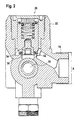
- the tap shown in Figure 1 has a body 10, for example in brass, with axial inlet connector 12 which has an external thread allowing the tap to be screwed onto a tank, for example a cylinder gas.
- the body 10 also includes an outlet connector 14 which communicates through an intermediate passage 16 with the inlet fitting 12.
- In this inner passage 16 is the main closing member, not shown, of the tap, which is actuated by an external operating flap 18.
- the tap further comprises, at the outlet connector 14, a another radial connection 22 into which a residual pressure valve 20 is screwed which is used to cut the interior passage 16 when the gas pressure drops in below a predetermined value.
- the valve 20 is located in such a closed position, preventing the gas from passing through the passage 16 to the outlet fitting 14.
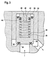
- the valve 20 is in the form of a compact cartridge (see Figure 3) comprising a cylindrical cap 24 which can be screwed into the fitting 22.
- the interior of the cap 24 forms a cylindrical housing 26 of a piston 28 also cylindrical and able to slide axially in the housing 26. There is no seal between the piston 28 and the cap, so gas under pressure can penetrate the wall of the piston 28 towards the bottom of the housing 26.
- annular seal 30 On the inner face of the piston 28 is an annular seal 30 which can be held in place between a peripheral edge 32 and a central wedge 34 can be screwed into the piston head 32 as in Figure 2, or which can simply be housed in a frontal groove as in FIG. 3.
- the seal 30 cooperates with an annular seat 36 of the valve body to interrupt, in the closed position of FIG. 2, the flow of gas from passage 16 towards the outlet fitting 14.
- the piston 28 On the face opposite to the seal 30, the piston 28 has an axial pocket cylindrical 38 in which there is a helical spring 40 which is compressed between the bottom of the pocket 38 and a cylindrical block also located partially or completely in the pocket depending on the position of the valve and resting on the bottom of the cap 24.
- the block 42 carries at its periphery a seal, for example an O-ring 44 which seals with the wall side of the pocket 38. This configuration therefore allows the piston 28 to slide axially relative to the cap 24 and relative to the block 42 under the action of the spring 40 or the pressure of the gases.
- the latter must, because the seal provided by the seal 44, be in communication with the bottom of the housing 26 in order to be able to expel the gases from the pocket when opening (decrease in the volume of the pocket 38) of the valve and suck up the gases during the closing the valve (increasing the volume of the bag 38).
- the block 42 has an axial channel 46 which is open on the bottom of the housing 26.
- a filter 48 which can be a sintered metal pellet.
- the filter can extend over the entire length of the channel or over a certain distance as in Figure 1.
- This metal can be crossed by gas but there is a certain resistance so as to slow down the axial movement of the piston 28 during opening and closing the valve and somehow playing a role of pneumatic damper. It was found that by braking the movement sufficiently in this way of the piston, it is possible to significantly reduce the resonant vibrations of the piston and even to eliminate them outright.
- the filter 48 is only one example of braking the passage of gases and can be replaced by equivalent means such as a very fine choke.
Landscapes
- Engineering & Computer Science (AREA)
- General Engineering & Computer Science (AREA)
- Mechanical Engineering (AREA)
- Details Of Valves (AREA)
- Safety Valves (AREA)
- Check Valves (AREA)
- Gas Separation By Absorption (AREA)
- Filling Or Discharging Of Gas Storage Vessels (AREA)
Applications Claiming Priority (2)
| Application Number | Priority Date | Filing Date | Title |
|---|---|---|---|
| LU90508 | 2000-01-24 | ||
| LU90508 | 2000-01-24 |
Publications (3)
| Publication Number | Publication Date |
|---|---|
| EP1120590A2 true EP1120590A2 (de) | 2001-08-01 |
| EP1120590A3 EP1120590A3 (de) | 2002-11-06 |
| EP1120590B1 EP1120590B1 (de) | 2003-09-10 |
Family
ID=19731861
Family Applications (1)
| Application Number | Title | Priority Date | Filing Date |
|---|---|---|---|
| EP01200112A Expired - Lifetime EP1120590B1 (de) | 2000-01-24 | 2001-01-15 | Ventil für komprimiertes oder flüssiges Gas |
Country Status (5)
| Country | Link |
|---|---|
| US (1) | US20010022351A1 (de) |
| EP (1) | EP1120590B1 (de) |
| JP (1) | JP2001248798A (de) |
| AT (1) | ATE249593T1 (de) |
| DE (1) | DE60100713D1 (de) |
Cited By (1)
| Publication number | Priority date | Publication date | Assignee | Title |
|---|---|---|---|---|
| WO2017129528A1 (en) * | 2016-01-25 | 2017-08-03 | Luxembourg Patent Company S.A. | High pressure valve with telescopic piston |
Families Citing this family (5)
| Publication number | Priority date | Publication date | Assignee | Title |
|---|---|---|---|---|
| EP1380779B1 (de) * | 2002-07-11 | 2004-11-10 | Luxembourg Patent Company S.A. | Druckbegrenzungsventil |
| US20040209133A1 (en) * | 2003-04-15 | 2004-10-21 | Hirsch Robert S. | Vapor feed fuel cell system with controllable fuel delivery |
| US7306869B2 (en) * | 2003-12-02 | 2007-12-11 | Mti Microfuel Cells Inc. | Electrostatically actuated shutter and array for use in a direct oxidation fuel cell |
| DE102005062573B4 (de) * | 2005-12-27 | 2017-08-17 | Wabco Gmbh | Steuerventil |
| US20070215220A1 (en) * | 2006-03-20 | 2007-09-20 | Bannon Thomas K | System for direct transfer of gas from a supply source to a portable cylinder and method for same |
Family Cites Families (3)
| Publication number | Priority date | Publication date | Assignee | Title |
|---|---|---|---|---|
| FR2671598B1 (fr) * | 1991-01-16 | 1993-04-16 | Tilles Mec | Robinet pour bouteilles de gaz comprimes ou liquefies. |
| AU691270B2 (en) * | 1994-06-24 | 1998-05-14 | Kabushiki Kaisha Neriki | Valve assembly for gas cylinder |
| GB9417168D0 (en) * | 1994-08-25 | 1994-10-12 | Delta Fluid Products Ltd | Flow control valve assembly |
-
2001
- 2001-01-15 DE DE60100713T patent/DE60100713D1/de not_active Expired - Lifetime
- 2001-01-15 EP EP01200112A patent/EP1120590B1/de not_active Expired - Lifetime
- 2001-01-15 AT AT01200112T patent/ATE249593T1/de not_active IP Right Cessation
- 2001-01-23 US US09/767,551 patent/US20010022351A1/en not_active Abandoned
- 2001-01-24 JP JP2001016159A patent/JP2001248798A/ja not_active Withdrawn
Cited By (3)
| Publication number | Priority date | Publication date | Assignee | Title |
|---|---|---|---|---|
| WO2017129528A1 (en) * | 2016-01-25 | 2017-08-03 | Luxembourg Patent Company S.A. | High pressure valve with telescopic piston |
| LU92958B1 (en) * | 2016-01-25 | 2017-08-07 | Luxembourg Patent Co | High pressure valve with telescopic piston |
| US10578223B2 (en) | 2016-01-25 | 2020-03-03 | Luxembourg Patent Company S.A. | High pressure valve with telescopic piston |
Also Published As
| Publication number | Publication date |
|---|---|
| EP1120590B1 (de) | 2003-09-10 |
| US20010022351A1 (en) | 2001-09-20 |
| ATE249593T1 (de) | 2003-09-15 |
| JP2001248798A (ja) | 2001-09-14 |
| DE60100713D1 (de) | 2003-10-16 |
| EP1120590A3 (de) | 2002-11-06 |
Similar Documents
| Publication | Publication Date | Title |
|---|---|---|
| EP0225225B1 (de) | Ventil zum Aufladen und nachfolgenden schnellen Entladen eines Behälters | |
| EP2870516B1 (de) | Druckmindererventil mit darin eingebauter restdruckfunktion | |
| FR2657668A1 (fr) | Robinet pour gaz comprime ou liquefie. | |
| EP0496091B1 (de) | Ventil für Druck- oder Flüssiggasflaschen | |
| EP1327803B1 (de) | Ventil für Druckbehälter | |
| FR2792387A1 (fr) | Raccord a soupapes pour un recipient sous pression | |
| EP1120590B1 (de) | Ventil für komprimiertes oder flüssiges Gas | |
| EP0246584B1 (de) | Ventil mit Membran | |
| FR2652426A1 (fr) | Detendeur de bouteille de gaz. | |
| FR2557950A1 (fr) | Perfectionnements apportes aux vannes a commande par piston | |
| FR2591706A1 (fr) | Soupape de surete a pilotage integre | |
| EP0774372B1 (de) | Verbesserte Tankentlüftungsvorrichtung für Kraftfahrzeugtank und Kraftfahrzeugtank mit dieser Vorrichtung | |
| EP0116247B1 (de) | Sicherheitsventil mit integrierter Pilotsteuerung | |
| FR2543504A1 (fr) | Soupape de limitation de pression pour des systemes de freinage a air comprime sur vehicules automobiles | |
| EP1380779B1 (de) | Druckbegrenzungsventil | |
| EP0516528B1 (de) | Sicherheitsventil für den Entlüftungskreislauf eines Kfz-Kraftstoffbehälters | |
| EP0428901B1 (de) | Neutralisierbares Reduzierventil | |
| CA2176394C (fr) | Procede de commande d'un dispositif de distribution pour l'alimentation d'une capacite avec un fluide gazeux, moyens pour la mise en oeuvre de ce procede et dispositif equipe de ces moyens | |
| FR2618868A1 (fr) | Dispositif formant detendeur de regulation automatique de pression d'un fluide gazeux | |
| FR2812093A1 (fr) | Robinet de detendeur integre avec raccord unique d'entree et sortie de fluide | |
| FR2734041A1 (fr) | Agencement de vanne pour bouteille de gaz | |
| EP1783575B1 (de) | Druckminderungsvorrichtung zur automatischen Regulierung des Nachdrucks eines gasförmigen Fluids | |
| LU88490A1 (fr) | Clapet de fermeture pour un extincteur d'incendie | |
| EP0993973B1 (de) | Steuervorrichtung für eine Radaufhängung eines Kraftfahrzeuges | |
| FR2477519A1 (fr) | Installation de distribution de boisson |
Legal Events
| Date | Code | Title | Description |
|---|---|---|---|
| PUAI | Public reference made under article 153(3) epc to a published international application that has entered the european phase |
Free format text: ORIGINAL CODE: 0009012 |
|
| AK | Designated contracting states |
Kind code of ref document: A2 Designated state(s): AT BE CH CY DE DK ES FI FR GB GR IE IT LI LU MC NL PT SE TR |
|
| AX | Request for extension of the european patent |
Free format text: AL;LT;LV;MK;RO;SI |
|
| PUAL | Search report despatched |
Free format text: ORIGINAL CODE: 0009013 |
|
| AK | Designated contracting states |
Kind code of ref document: A3 Designated state(s): AT BE CH CY DE DK ES FI FR GB GR IE IT LI LU MC NL PT SE TR |
|
| AX | Request for extension of the european patent |
Free format text: AL;LT;LV;MK;RO;SI |
|
| 17P | Request for examination filed |
Effective date: 20030110 |
|
| GRAH | Despatch of communication of intention to grant a patent |
Free format text: ORIGINAL CODE: EPIDOS IGRA |
|
| GRAH | Despatch of communication of intention to grant a patent |
Free format text: ORIGINAL CODE: EPIDOS IGRA |
|
| AKX | Designation fees paid |
Designated state(s): AT BE CH CY DE DK ES FI FR GB GR IE IT LI LU MC NL PT SE TR |
|
| GRAA | (expected) grant |
Free format text: ORIGINAL CODE: 0009210 |
|
| AK | Designated contracting states |
Kind code of ref document: B1 Designated state(s): AT BE CH CY DE DK ES FI FR GB GR IE IT LI LU MC NL PT SE TR |
|
| PG25 | Lapsed in a contracting state [announced via postgrant information from national office to epo] |
Ref country code: IT Free format text: LAPSE BECAUSE OF FAILURE TO SUBMIT A TRANSLATION OF THE DESCRIPTION OR TO PAY THE FEE WITHIN THE PRE;WARNING: LAPSES OF ITALIAN PATENTS WITH EFFECTIVE DATE BEFORE 2007 MAY HAVE OCCURRED AT ANY TIME BEFORE 2007. THE CORRECT EFFECTIVE DATE MAY BE DIFFERENT FROM THE ONE RECORDED.SCRIBED TIME-LIMIT Effective date: 20030910 Ref country code: IE Free format text: LAPSE BECAUSE OF FAILURE TO SUBMIT A TRANSLATION OF THE DESCRIPTION OR TO PAY THE FEE WITHIN THE PRESCRIBED TIME-LIMIT Effective date: 20030910 Ref country code: GB Free format text: LAPSE BECAUSE OF FAILURE TO SUBMIT A TRANSLATION OF THE DESCRIPTION OR TO PAY THE FEE WITHIN THE PRESCRIBED TIME-LIMIT Effective date: 20030910 Ref country code: ES Free format text: LAPSE BECAUSE OF FAILURE TO SUBMIT A TRANSLATION OF THE DESCRIPTION OR TO PAY THE FEE WITHIN THE PRESCRIBED TIME-LIMIT Effective date: 20030910 Ref country code: NL Free format text: LAPSE BECAUSE OF FAILURE TO SUBMIT A TRANSLATION OF THE DESCRIPTION OR TO PAY THE FEE WITHIN THE PRESCRIBED TIME-LIMIT Effective date: 20030910 Ref country code: AT Free format text: LAPSE BECAUSE OF FAILURE TO SUBMIT A TRANSLATION OF THE DESCRIPTION OR TO PAY THE FEE WITHIN THE PRESCRIBED TIME-LIMIT Effective date: 20030910 Ref country code: CY Free format text: LAPSE BECAUSE OF FAILURE TO SUBMIT A TRANSLATION OF THE DESCRIPTION OR TO PAY THE FEE WITHIN THE PRESCRIBED TIME-LIMIT Effective date: 20030910 Ref country code: TR Free format text: LAPSE BECAUSE OF FAILURE TO SUBMIT A TRANSLATION OF THE DESCRIPTION OR TO PAY THE FEE WITHIN THE PRESCRIBED TIME-LIMIT Effective date: 20030910 Ref country code: FI Free format text: LAPSE BECAUSE OF FAILURE TO SUBMIT A TRANSLATION OF THE DESCRIPTION OR TO PAY THE FEE WITHIN THE PRESCRIBED TIME-LIMIT Effective date: 20030910 |
|
| REG | Reference to a national code |
Ref country code: GB Ref legal event code: FG4D Free format text: NOT ENGLISH |
|
| REG | Reference to a national code |
Ref country code: CH Ref legal event code: EP |
|
| REF | Corresponds to: |
Ref document number: 60100713 Country of ref document: DE Date of ref document: 20031016 Kind code of ref document: P |
|
| REG | Reference to a national code |
Ref country code: IE Ref legal event code: FG4D Free format text: FRENCH |
|
| PG25 | Lapsed in a contracting state [announced via postgrant information from national office to epo] |
Ref country code: DK Free format text: LAPSE BECAUSE OF FAILURE TO SUBMIT A TRANSLATION OF THE DESCRIPTION OR TO PAY THE FEE WITHIN THE PRESCRIBED TIME-LIMIT Effective date: 20031210 Ref country code: GR Free format text: LAPSE BECAUSE OF FAILURE TO SUBMIT A TRANSLATION OF THE DESCRIPTION OR TO PAY THE FEE WITHIN THE PRESCRIBED TIME-LIMIT Effective date: 20031210 Ref country code: SE Free format text: LAPSE BECAUSE OF FAILURE TO SUBMIT A TRANSLATION OF THE DESCRIPTION OR TO PAY THE FEE WITHIN THE PRESCRIBED TIME-LIMIT Effective date: 20031210 |
|
| PG25 | Lapsed in a contracting state [announced via postgrant information from national office to epo] |
Ref country code: DE Free format text: LAPSE BECAUSE OF FAILURE TO SUBMIT A TRANSLATION OF THE DESCRIPTION OR TO PAY THE FEE WITHIN THE PRESCRIBED TIME-LIMIT Effective date: 20031211 |
|
| PG25 | Lapsed in a contracting state [announced via postgrant information from national office to epo] |
Ref country code: PT Free format text: LAPSE BECAUSE OF FAILURE TO SUBMIT A TRANSLATION OF THE DESCRIPTION OR TO PAY THE FEE WITHIN THE PRESCRIBED TIME-LIMIT Effective date: 20031219 |
|
| PG25 | Lapsed in a contracting state [announced via postgrant information from national office to epo] |
Ref country code: LU Free format text: LAPSE BECAUSE OF NON-PAYMENT OF DUE FEES Effective date: 20040115 |
|
| PG25 | Lapsed in a contracting state [announced via postgrant information from national office to epo] |
Ref country code: BE Free format text: LAPSE BECAUSE OF NON-PAYMENT OF DUE FEES Effective date: 20040131 Ref country code: MC Free format text: LAPSE BECAUSE OF NON-PAYMENT OF DUE FEES Effective date: 20040131 |
|
| NLV1 | Nl: lapsed or annulled due to failure to fulfill the requirements of art. 29p and 29m of the patents act | ||
| GBV | Gb: ep patent (uk) treated as always having been void in accordance with gb section 77(7)/1977 [no translation filed] |
Effective date: 20030910 |
|
| REG | Reference to a national code |
Ref country code: IE Ref legal event code: FD4D |
|
| PLBE | No opposition filed within time limit |
Free format text: ORIGINAL CODE: 0009261 |
|
| STAA | Information on the status of an ep patent application or granted ep patent |
Free format text: STATUS: NO OPPOSITION FILED WITHIN TIME LIMIT |
|
| BERE | Be: lapsed |
Owner name: S.A. *LUXEMBOURG PATENT CY Effective date: 20040131 |
|
| 26N | No opposition filed |
Effective date: 20040614 |
|
| PG25 | Lapsed in a contracting state [announced via postgrant information from national office to epo] |
Ref country code: FR Free format text: LAPSE BECAUSE OF NON-PAYMENT OF DUE FEES Effective date: 20040930 |
|
| REG | Reference to a national code |
Ref country code: FR Ref legal event code: ST |
|
| PG25 | Lapsed in a contracting state [announced via postgrant information from national office to epo] |
Ref country code: CH Free format text: LAPSE BECAUSE OF NON-PAYMENT OF DUE FEES Effective date: 20050131 Ref country code: LI Free format text: LAPSE BECAUSE OF NON-PAYMENT OF DUE FEES Effective date: 20050131 |
|
| REG | Reference to a national code |
Ref country code: CH Ref legal event code: PL |