EP1120596B1 - Accouplement de secours en response à une forte traction axiale - Google Patents
Accouplement de secours en response à une forte traction axiale Download PDFInfo
- Publication number
- EP1120596B1 EP1120596B1 EP01200203A EP01200203A EP1120596B1 EP 1120596 B1 EP1120596 B1 EP 1120596B1 EP 01200203 A EP01200203 A EP 01200203A EP 01200203 A EP01200203 A EP 01200203A EP 1120596 B1 EP1120596 B1 EP 1120596B1
- Authority
- EP
- European Patent Office
- Prior art keywords
- coupling
- valve
- duct
- segment
- sliding
- Prior art date
- Legal status (The legal status is an assumption and is not a legal conclusion. Google has not performed a legal analysis and makes no representation as to the accuracy of the status listed.)
- Expired - Lifetime
Links
- 230000008878 coupling Effects 0.000 title claims description 82
- 238000010168 coupling process Methods 0.000 title claims description 82
- 238000005859 coupling reaction Methods 0.000 title claims description 82
- 230000033001 locomotion Effects 0.000 claims description 28
- 239000012530 fluid Substances 0.000 claims description 10
- 238000000926 separation method Methods 0.000 claims description 8
- 230000007246 mechanism Effects 0.000 claims description 6
- 230000006835 compression Effects 0.000 claims description 2
- 238000007906 compression Methods 0.000 claims description 2
- 238000012856 packing Methods 0.000 description 4
- 230000000694 effects Effects 0.000 description 2
- 238000005452 bending Methods 0.000 description 1
- 230000015572 biosynthetic process Effects 0.000 description 1
- 230000006866 deterioration Effects 0.000 description 1
- 230000003628 erosive effect Effects 0.000 description 1
- JEIPFZHSYJVQDO-UHFFFAOYSA-N iron(III) oxide Inorganic materials O=[Fe]O[Fe]=O JEIPFZHSYJVQDO-UHFFFAOYSA-N 0.000 description 1
- 230000002093 peripheral effect Effects 0.000 description 1
- 239000007787 solid Substances 0.000 description 1
Images


Classifications
-
- F—MECHANICAL ENGINEERING; LIGHTING; HEATING; WEAPONS; BLASTING
- F16—ENGINEERING ELEMENTS AND UNITS; GENERAL MEASURES FOR PRODUCING AND MAINTAINING EFFECTIVE FUNCTIONING OF MACHINES OR INSTALLATIONS; THERMAL INSULATION IN GENERAL
- F16L—PIPES; JOINTS OR FITTINGS FOR PIPES; SUPPORTS FOR PIPES, CABLES OR PROTECTIVE TUBING; MEANS FOR THERMAL INSULATION IN GENERAL
- F16L29/00—Joints with fluid cut-off means
- F16L29/04—Joints with fluid cut-off means with a cut-off device in each of the two pipe ends, the cut-off devices being automatically opened when the coupling is applied
Definitions
- the present invention concerns a coupling for hydraulic tubing with emergency uncoupling and hydraulic closing in conditions of strong axial traction.
- couplings that are made up of two parts that are passed through by respective axial ducts, which are connected by rigid connection means that are suitable to allow the automatic separation of the aforesaid parts in the case of an axial traction higher than a predetermined limit.
- At least one of said parts comprises a means for the interception of the flow of fluid that is made up of a spherical segment valve that responds to the separation movement of the two parts of the coupling with a combined motion of rotation around an axis perpendicular to the longitudinal axis of the respective axial duct and of sliding along said longitudinal axis up to the attainment of a closing position.
- a coupling of this type according to the preamble of claim 1 is described in WO-A-99/17044 and for the aforesaid spherical segment valve it provides for at least a mechanism of rotary-sliding operation comprising at least a sliding rack rod and at least a toothed segment that are co-operating from opposite sides with at least one toothed wheel that creates a driving hinge of said valve.
- elastic means that through a sliding disc thrust said rack rod towards a closing position of said valve, locking means that, when the coupling is coupled, keep said valve in opening position, and cylinders and piston means connected with said rack rod in order to control the feeding speed of said rack rod towards the closing position of said valve.
- the aforesaid locking means are made up of a segment of duct fastened to the other part of the coupling or freely interposed between the two parts of the coupling, against which the spherical segment valve abuts when the coupling is coupled.
- segment of duct for the locking of the valve into a closing position determines the requirement for two equally important measures: one is to avoid a discontinuity between said segment of duct and the axial ducts of the two parts of the coupling, so as to prevent that the fluid being transported invades the mechanisms responsible for the operation of the valve, consequently determining difficulty in movement, erosions, formation of rust and so on; another, not easy to combine with the previous one, is to assure that the aforesaid segment of duct brings itself in unlocking position before the closing movement of the valve has begun, so as to prevent mechanical interference between the two.
- Object of the present invention is to realise a coupling of the aforementioned type that meets both of the aforesaid requirements.
- a coupling for hydraulic tubing that is made up of two parts of coupling that are passed through by respective axial ducts for the flow of fluid and are connected with each other by rigid coupling means that are suitable to allow the automatic separation of the same parts in case of an axial traction higher than a predetermined limit
- at least one first part of the coupling comprising a means for the interception of the flow of fluid that is made up of a spherical segment valve that responds to the movement of separation of the two parts of the coupling with a combined motion of rotation around an axis perpendicular to the longitudinal axis of the respective axial duct and of sliding along said longitudinal axis up to the attainment of a closing position
- said valve being provided with a rotary-sliding drive mechanism comprising at least one sliding rack rod and at least one toothed segment that are co-operating from opposite sides with at least one toothed wheel making up a driving hinge for said valve, and there being provided elastic means that thrust said rack rod toward
- the transported fluid remains confined inside the duct destined to it and it does not involve the operating mechanisms of the valve and at the same time it assures that the duct segment that maintains the valve in opening condition does not interfere in any way with the closing movement of the same valve in case of an uncoupling determined by strong axial stresses.
- both parts of the coupling can be provided with a spherical segment valve with rotary-sliding movement with relative operating mechanism and in such case the characteristics that are described for the first part of the coupling must be repeated for the second part of the same coupling, that is the duct segment that is utilised for the locking of the valve of the second part of the coupling is positined in a similar way as regards the relative axial duct and it is also subjected to a movement of axial expulsion from said second part of the coupling before the aforesaid valve is controlled to execute a closing movement.
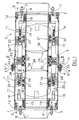
- the coupling for tubing that is illustrated in the drawings is the two valves type and it comprises a first and a second part 1 and 2 that are fastenable to each other by means of a circumferencial series of fracture screws of 3 having an intermediate segment 4 with a reduced section and therefore weakened (Fig. 1).
- Each of said parts 1 and 2 of the coupling comprises a first and a second the terminal flange 5 and 6, to the first one of which a respective tubing 8 is fastenable by means of screws 7 .
- a cylindrical duct 10 defining an axial passage for the flow of fluid that flows through the coupling extends in opposite sense, axially aligned with said tubing 8.
- a cylindrical coupling box 11 that has one end fastened to the flange 5 by means of screws 12 and that ends at the other end with the flange 6 still extends from the flange 5 .
- an external flange 51 is welded that, when the coupling is coupled, is set against a corresponding external flange 52 made up of solid piece with an annular band 53 welded around the terminal flange 6 of the part of coupling 2 and extending axially from it so as to surround the terminal flange 6 of the part of coupling 1 in sliding engagement.
- the fracture screws 3 are set as a connection of two external flanges 51 and 52.
- a disc 14 is arranged in axially sliding way on the duct 10, that it is thrust toward the right (looking at Fig. 1) by a compression spring 15, possibly substitutable by several springs coaxial to each other.
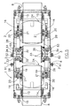
- a spherical segment valve 24 (1/4 of a sphere in the example herein reported) is hinged, than owing to the rotary-sliding motion of the toothed wheels 20 can be displaced from the opening position illustrated in Fig. 1 to the closing position illustrated in Figures 11 and 12. In this latter position the spherical back 25 of the valve is not only rotated perpendicular to the axis of the coupling but it is also pressed against one annular seal packing 26 that is embedded in a corresponding housing of flange 6.
- Each rack rod 16 ends with a piston 27 that is slidingly housed inside a respective cylinder 28 fastened to the flange 6.
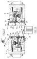
- the cylinder 28 is normally filled with oil not in pressure, than in case of feeding of the piston 27 as regards the position of Fig. 1, as it will be better explained later, can protrude at a controlled speed through a gauged hole 29 that is connected by small tubes 30 to a lateral vent opening 31 ( Figures 2 and 3).
- a stem 32 extends, that slidingly passes through the same flange 6 and engages with a lever 33 that has an end hinged in 39 on the external face of flange 6.
- the other end of lever 33 is in abutment engagement with a radial projection 34 of a segment of cylindrical duct 35 that, when the coupling is coupled, is placed in intermediate position between the ducts 10 of the two parts of the coupling and as axial connection of the same ducts 10, that is made watertight by the presence of the packings 36 ( Figures 1 and 2).
- Additional packings 37 are interposed between the segment of duct 35 and the flanges 6 of the two parts of the coupling.
- the intermediate segment of duct 35 when the coupling is coupled, serves as a locking mean so as to keep the two valves 24 in an opening position.
- a chain 38 keeps the segment of duct 35 coupled to the flange 6 of one of the two parts of the coupling ( Figures 2 and 3).
- the two valves 24 can therefore reach the position of closing and engagement with the packings 26 that is illustrated in Figures 11-13, without any possibility for the segment of duct 35 to interfere with their rotary-sliding movements.
- the intermediate section of the duct 35 is kept attached to the part 1 of the coupling by the chain 38 (Fig. 12).
Landscapes
- Engineering & Computer Science (AREA)
- General Engineering & Computer Science (AREA)
- Mechanical Engineering (AREA)
- Quick-Acting Or Multi-Walled Pipe Joints (AREA)
- Joints That Cut Off Fluids, And Hose Joints (AREA)
- Mutual Connection Of Rods And Tubes (AREA)
Claims (7)
- Accouplement pour un tubage hydraulique constitué de deux parties d'accouplement (1, 2) qui sont traversées par des conduits axiaux respectifs (10) pour l'écoulement d'un fluide et connectées l'une à l'autre par des moyens d'accouplement rigides (3) appropriés pour permettre la séparation automatique desdites parties en cas de traction axiale supérieure à une limite prédéterminée, au moins une première partie (1, 2) de l'accouplement comprenant des moyens pour intercepter l'écoulement de fluide constitués d'une soupape à segment sphérique (24) qui répond au déplacement de séparation des deux parties (1, 2) de l'accouplement avec un mouvement de rotation combiné autour d'un axe perpendiculaire à l'axe longitudinal du conduit axial respectif (10) et en coulissant le long dudit axe longitudinal jusqu'à atteindre une position fermée, ladite soupape (24) comprenant un mécanisme d'entraînement coulissant - rotatif comprenant au moins une crémaillère coulissante (16) et au moins un segment denté (19) qui coopèrent à partir de côtés opposés avec au moins une roue dentée (20) constituant une charnière d'entraînement (21) pour ladite soupape (24), dans lequel des moyens élastiques (15) sont prévus pour pousser ladite crémaillère (16) vers une position appropriée pour déterminer la fermeture de ladite soupape (24), des moyens de verrouillage (35) qui, lorsque l'accouplement est accouplé, maintiennent ladite soupape (24) dans une position ouverte, et des moyens de résistance (28, 27) connectés à ladite crémaillère (16) pour commander la vitesse d'entraînement de ladite crémaillère (16) vers la position fermée de ladite soupape (24), lesdits moyens de verrouillage (35) étant constitués d'un segment de conduit (35) agencé comme une extension du conduit axial (10) de la première partie de l'accouplement et contre lequel ladite soupape (24) bute lorsque l'accouplement est accouplé, caractérisé en ce que ledit segment de conduit (35) est en contact intime avec ledit conduit axial (10) de la première partie de l'accouplement, et ladite crémaillère (16) est appropriée pour agir sur ledit segment de conduit (35) pour commander son déplacement axial d'expulsion à partir de la première partie de l'accouplement, et est en outre connecté de façon opérationnelle à ladite soupape (24) de manière à commander le commencement de son déplacement de fermeture uniquement après que ledit déplacement axial d'expulsion du segment de conduit (35) a déterminé l'enlèvement du même segment de conduit (35) du chemin du déplacement de fermeture de ladite soupape (24).
- Accouplement selon la revendication 1, caractérisé en ce que ladite crémaillère (16) agit sur ledit segment de conduit (35) à travers une tige (32) qui est montée fixement sur ladite crémaillère (16) et appuie contre un levier (33) qui est approprié pour produire un déplacement d'expulsion dudit segment de conduit (35).
- Accouplement selon la revendication 2, caractérisé en ce que lesdits moyens de résistance (28, 27) comprennent un piston (27) qui est attaché à une extrémité de ladite crémaillère (16) et coulisse à l'intérieur d'un cylindre hydraulique (28) comportant un trou calibré (29) pour la sortie du débit d'un fluide hydraulique qui n'est normalement pas pressurisé et qui est contenu à l'intérieur dudit cylindre (28), ladite tige (32) s'étendant axialement à partir dudit piston (27) à l'intérieur dudit cylindre (28) de telle sorte que, à la suite de l'arrivée de ladite crémaillère (16), ladite tige (32) fasse saillie axialement hors dudit cylindre (28) pour agir sur ledit levier (33) pour expulser ledit segment de conduit (35).
- Accouplement selon la revendication 1, caractérisé en ce que ledit segment denté (19) est supporté par un support fixe (18) avec une possibilité limitée de jeu de coulissement axial, et ladite soupape (24) est attachée à ladite charnière de rotation (21) de ladite roue dentée (20) avec une possibilité limitée de jeu de rotation, de telle sorte qu'une partie initiale du déplacement d'entraînement de la crémaillère (16) peut déterminer seulement un coulissement axial dudit segment denté (19) et une rotation de ladite roue dentée (20) sans qu'un déplacement coulissant simultané de ladite roue dentée (20) et qu'un déplacement coulissant et rotatif simultané de ladite soupape (24) se produisent.
- Accouplement selon la revendication 1, caractérisé en ce que lesdits moyens élastiques (15) sont constitués d'au moins un ressort de compression (15) agissant sur un disque coulissant (14) attaché à l'autre extrémité de ladite crémaillère (16).
- Accouplement selon la revendication 1, caractérisé en ce que lesdits moyens d'accouplement rigide (3) sont constitués de vis fracturables (3) présentant une section intermédiaire affaiblie (4).
- Accouplement selon la revendication 6, caractérisé en ce que lesdites vis fracturables (3) sont posées comme une connexion entre une bride externe (51) attachée à une desdites parties (1, 2) de l'accouplement et une autre bride externe (52) attachée à une bande extérieure (53) qui est attachée à l'autre partie de l'accouplement et s'étend axialement à partir de celle-ci de manière à entourer l'extrémité opposée de ladite partie de l'accouplement dans un engagement coulissant.
Applications Claiming Priority (2)
| Application Number | Priority Date | Filing Date | Title |
|---|---|---|---|
| ITMI000078 | 2000-01-24 | ||
| IT2000MI000078A IT1316297B1 (it) | 2000-01-24 | 2000-01-24 | Raccordo per tubazioni idrauliche con sgancio e chiusura idraulica diemergenza in condizioni di forte trazione assiale |
Publications (2)
| Publication Number | Publication Date |
|---|---|
| EP1120596A1 EP1120596A1 (fr) | 2001-08-01 |
| EP1120596B1 true EP1120596B1 (fr) | 2007-03-14 |
Family
ID=11443747
Family Applications (1)
| Application Number | Title | Priority Date | Filing Date |
|---|---|---|---|
| EP01200203A Expired - Lifetime EP1120596B1 (fr) | 2000-01-24 | 2001-01-19 | Accouplement de secours en response à une forte traction axiale |
Country Status (3)
| Country | Link |
|---|---|
| EP (1) | EP1120596B1 (fr) |
| ES (1) | ES2283372T3 (fr) |
| IT (1) | IT1316297B1 (fr) |
Families Citing this family (1)
| Publication number | Priority date | Publication date | Assignee | Title |
|---|---|---|---|---|
| US9919774B2 (en) | 2010-05-20 | 2018-03-20 | Excelerate Energy Limited Partnership | Systems and methods for treatment of LNG cargo tanks |
Family Cites Families (3)
| Publication number | Priority date | Publication date | Assignee | Title |
|---|---|---|---|---|
| US5365973A (en) * | 1993-10-25 | 1994-11-22 | Husky Corporation | Break-away concentric hose coupling |
| US5546986A (en) * | 1995-02-07 | 1996-08-20 | Clark Technology Systems, Inc. | Leakproof dual action fluid transfer valve |
| IT1295092B1 (it) * | 1997-09-29 | 1999-04-27 | Valagem Servicos E Gestao Lda | Raccordo per tubazioni con sgancio automatico e immediata chiusura idraulica in risposta a una forte trazione assiale |
-
2000
- 2000-01-24 IT IT2000MI000078A patent/IT1316297B1/it active
-
2001
- 2001-01-19 ES ES01200203T patent/ES2283372T3/es not_active Expired - Lifetime
- 2001-01-19 EP EP01200203A patent/EP1120596B1/fr not_active Expired - Lifetime
Also Published As
| Publication number | Publication date |
|---|---|
| IT1316297B1 (it) | 2003-04-10 |
| EP1120596A1 (fr) | 2001-08-01 |
| ITMI20000078A1 (it) | 2001-07-24 |
| ES2283372T3 (es) | 2007-11-01 |
| ITMI20000078A0 (it) | 2000-01-24 |
Similar Documents
| Publication | Publication Date | Title |
|---|---|---|
| EP2863005B1 (fr) | Joint de déclenchement | |
| US20140137680A1 (en) | Mechanical actuator with a hydraulic damper device | |
| US3902694A (en) | Swinging spherical gate valve and double seal quick disconnect coupling | |
| US5419235A (en) | Power steering gear assembly | |
| JP5718381B2 (ja) | 自閉式停止弁に用いられる流れ制御アクチュエータ装置 | |
| US7191791B2 (en) | Device for actuating double seat valves | |
| EP0006278B1 (fr) | Raccord à rupture pour conduite | |
| EP0803651B1 (fr) | Dispositif d'actionnement hydraulique | |
| US6056011A (en) | Pipe fitting provided with two ball valves, one of which with concavity, that are activated in a sequence and with quick release coupling means subordinated to the closing of both valves | |
| WO2018236223A2 (fr) | Dispositif d'étanchéité de soupape | |
| EP1120596B1 (fr) | Accouplement de secours en response à une forte traction axiale | |
| WO2018065761A1 (fr) | Raccord de conduite | |
| US20140097363A1 (en) | Floating seal retainer | |
| US12104712B1 (en) | Lever operated dump valve with improved accuracy | |
| EP0023120B1 (fr) | Dispositif de manoeuvre actionné par fluide comportant un dispositif de securité amovible | |
| EP4063071B1 (fr) | Unité d'actionnement | |
| US7353921B2 (en) | Self aligning brake kit | |
| US3688644A (en) | Fluid operated actuator for movable members | |
| EP3652472B1 (fr) | Actionneur pour distributeurs à tiroir | |
| US20190072205A1 (en) | Control valve for a process plant | |
| EP1044341B1 (fr) | Raccord de tuyau avec decharge automatique et fermeture immediate de joint hydraulique en reaction a une forte traction axiale | |
| FI77096C (fi) | Hydrauliskt manoevreringsorgan foer reglering av ventiler. | |
| US4549636A (en) | Disc brakes for vehicles | |
| CN109649664A (zh) | 联接释放装置 | |
| EP3204277B1 (fr) | Dispositif d'équilibrage de pression pour systèmes hydrauliques de freinage |
Legal Events
| Date | Code | Title | Description |
|---|---|---|---|
| PUAI | Public reference made under article 153(3) epc to a published international application that has entered the european phase |
Free format text: ORIGINAL CODE: 0009012 |
|
| AK | Designated contracting states |
Kind code of ref document: A1 Designated state(s): ES FR GB IT |
|
| AX | Request for extension of the european patent |
Free format text: AL;LT;LV;MK;RO;SI |
|
| 17P | Request for examination filed |
Effective date: 20011205 |
|
| AKX | Designation fees paid |
Free format text: ES FR GB IT |
|
| REG | Reference to a national code |
Ref country code: DE Ref legal event code: 8566 |
|
| GRAP | Despatch of communication of intention to grant a patent |
Free format text: ORIGINAL CODE: EPIDOSNIGR1 |
|
| GRAS | Grant fee paid |
Free format text: ORIGINAL CODE: EPIDOSNIGR3 |
|
| RAP1 | Party data changed (applicant data changed or rights of an application transferred) |
Owner name: BORMIOLI, MARINA Owner name: BORMIOLI, LORENZO |
|
| RIN1 | Information on inventor provided before grant (corrected) |
Inventor name: BORMIOLI, LORENZO Inventor name: BORMIOLI, MARINA |
|
| GRAA | (expected) grant |
Free format text: ORIGINAL CODE: 0009210 |
|
| AK | Designated contracting states |
Kind code of ref document: B1 Designated state(s): ES FR GB IT |
|
| REG | Reference to a national code |
Ref country code: GB Ref legal event code: FG4D |
|
| REG | Reference to a national code |
Ref country code: ES Ref legal event code: FG2A Ref document number: 2283372 Country of ref document: ES Kind code of ref document: T3 |
|
| PLBE | No opposition filed within time limit |
Free format text: ORIGINAL CODE: 0009261 |
|
| STAA | Information on the status of an ep patent application or granted ep patent |
Free format text: STATUS: NO OPPOSITION FILED WITHIN TIME LIMIT |
|
| 26N | No opposition filed |
Effective date: 20071217 |
|
| REG | Reference to a national code |
Ref country code: FR Ref legal event code: PLFP Year of fee payment: 16 |
|
| REG | Reference to a national code |
Ref country code: FR Ref legal event code: PLFP Year of fee payment: 17 |
|
| REG | Reference to a national code |
Ref country code: FR Ref legal event code: PLFP Year of fee payment: 18 |
|
| PGFP | Annual fee paid to national office [announced via postgrant information from national office to epo] |
Ref country code: GB Payment date: 20200121 Year of fee payment: 20 Ref country code: ES Payment date: 20200205 Year of fee payment: 20 Ref country code: IT Payment date: 20200124 Year of fee payment: 20 |
|
| PGFP | Annual fee paid to national office [announced via postgrant information from national office to epo] |
Ref country code: FR Payment date: 20200128 Year of fee payment: 20 |
|
| REG | Reference to a national code |
Ref country code: GB Ref legal event code: PE20 Expiry date: 20210118 |
|
| PG25 | Lapsed in a contracting state [announced via postgrant information from national office to epo] |
Ref country code: GB Free format text: LAPSE BECAUSE OF EXPIRATION OF PROTECTION Effective date: 20210118 |
|
| REG | Reference to a national code |
Ref country code: ES Ref legal event code: FD2A Effective date: 20210728 |
|
| PG25 | Lapsed in a contracting state [announced via postgrant information from national office to epo] |
Ref country code: ES Free format text: LAPSE BECAUSE OF EXPIRATION OF PROTECTION Effective date: 20210120 |