EP1120626A2 - Vorrichtung zur Bestimmung der Winkelposition - Google Patents
Vorrichtung zur Bestimmung der Winkelposition Download PDFInfo
- Publication number
- EP1120626A2 EP1120626A2 EP01101719A EP01101719A EP1120626A2 EP 1120626 A2 EP1120626 A2 EP 1120626A2 EP 01101719 A EP01101719 A EP 01101719A EP 01101719 A EP01101719 A EP 01101719A EP 1120626 A2 EP1120626 A2 EP 1120626A2
- Authority
- EP
- European Patent Office
- Prior art keywords
- magnets
- angular position
- measuring device
- stator core
- position measuring
- Prior art date
- Legal status (The legal status is an assumption and is not a legal conclusion. Google has not performed a legal analysis and makes no representation as to the accuracy of the status listed.)
- Granted
Links
- 230000004907 flux Effects 0.000 claims abstract description 61
- 230000008859 change Effects 0.000 claims abstract description 10
- 230000002940 repellent Effects 0.000 claims abstract description 7
- 239000005871 repellent Substances 0.000 claims abstract description 7
- 239000012141 concentrate Substances 0.000 claims description 6
- 230000003247 decreasing effect Effects 0.000 abstract description 6
- 230000007423 decrease Effects 0.000 description 7
- 230000004048 modification Effects 0.000 description 7
- 238000012986 modification Methods 0.000 description 7
- 230000002093 peripheral effect Effects 0.000 description 5
- 238000009434 installation Methods 0.000 description 4
- 125000006850 spacer group Chemical group 0.000 description 4
- 230000000694 effects Effects 0.000 description 3
- XEEYBQQBJWHFJM-UHFFFAOYSA-N Iron Chemical compound [Fe] XEEYBQQBJWHFJM-UHFFFAOYSA-N 0.000 description 2
- 239000000853 adhesive Substances 0.000 description 2
- 230000001070 adhesive effect Effects 0.000 description 2
- 230000003321 amplification Effects 0.000 description 2
- 238000002485 combustion reaction Methods 0.000 description 2
- 239000000696 magnetic material Substances 0.000 description 2
- 238000004519 manufacturing process Methods 0.000 description 2
- 238000003199 nucleic acid amplification method Methods 0.000 description 2
- 239000012260 resinous material Substances 0.000 description 2
- 241001481828 Glyptocephalus cynoglossus Species 0.000 description 1
- 230000015572 biosynthetic process Effects 0.000 description 1
- 229910052742 iron Inorganic materials 0.000 description 1
- 230000001788 irregular Effects 0.000 description 1
- 238000005259 measurement Methods 0.000 description 1
- 230000009467 reduction Effects 0.000 description 1
- 230000000717 retained effect Effects 0.000 description 1
- 238000005728 strengthening Methods 0.000 description 1
- 238000009966 trimming Methods 0.000 description 1
Images




Classifications
-
- G—PHYSICS
- G01—MEASURING; TESTING
- G01D—MEASURING NOT SPECIALLY ADAPTED FOR A SPECIFIC VARIABLE; ARRANGEMENTS FOR MEASURING TWO OR MORE VARIABLES NOT COVERED IN A SINGLE OTHER SUBCLASS; TARIFF METERING APPARATUS; MEASURING OR TESTING NOT OTHERWISE PROVIDED FOR
- G01D5/00—Mechanical means for transferring the output of a sensing member; Means for converting the output of a sensing member to another variable where the form or nature of the sensing member does not constrain the means for converting; Transducers not specially adapted for a specific variable
- G01D5/12—Mechanical means for transferring the output of a sensing member; Means for converting the output of a sensing member to another variable where the form or nature of the sensing member does not constrain the means for converting; Transducers not specially adapted for a specific variable using electric or magnetic means
- G01D5/14—Mechanical means for transferring the output of a sensing member; Means for converting the output of a sensing member to another variable where the form or nature of the sensing member does not constrain the means for converting; Transducers not specially adapted for a specific variable using electric or magnetic means influencing the magnitude of a current or voltage
- G01D5/142—Mechanical means for transferring the output of a sensing member; Means for converting the output of a sensing member to another variable where the form or nature of the sensing member does not constrain the means for converting; Transducers not specially adapted for a specific variable using electric or magnetic means influencing the magnitude of a current or voltage using Hall-effect devices
- G01D5/145—Mechanical means for transferring the output of a sensing member; Means for converting the output of a sensing member to another variable where the form or nature of the sensing member does not constrain the means for converting; Transducers not specially adapted for a specific variable using electric or magnetic means influencing the magnitude of a current or voltage using Hall-effect devices influenced by the relative movement between the Hall device and magnetic fields
Definitions
- the present invention relates generally to an improved structure of a device for measuring an angular position of an object using a magnetic detector and magnets, and more particularly to a compact and high-accuracy angular position measuring device.
- U.S.P. No. 5,861,745 Japanese Patent First Publication No. 2920179, PCT:WO98/080601 discloses an angular position measuring device using a magnetic detector such as a Hall element and magnets.
- Fig. 19 shows one example of conventional angular position measuring devices designed to measure an opened position of a throttle valve of an internal combustion engine.
- the device includes a cylindrical rotor core (i.e., a yoke) 11 rotating along with the throttle valve (not shown) and a stator core 12 disposed coaxially within the rotor core 11. Disposed between the rotor core 11 and the stator core 12 are two arc-shaped magnets 13 which are diametrically opposed to each other. Each of the magnets 13 is so magnetized that all lines of magnetic force are oriented in a radius direction of the magnet 13.
- a magnetic gap 14 is formed in the stator core 12 which has a constant width and extends through the center of the stator core 12 in a diameter direction.
- a magnetic detector such as a Hall IC is disposed at the center of the magnetic gap 14.
- the density of a magnetic flux through the magnetic gap 14 in the stator core 12 changes as a function of an angular position of the rotor core 11.
- the magnetic detector 15 produces an output as a function of the magnetic flux density. Specifically, the angular position of the rotor core 11, or the opened position of the throttle valve is determined using the output of the magnetic detector 15.
- the arc-shaped magnets 13 are, as described above, magnetized radially. Uniformly magnetizing the magnets 13 requires decreasing the magnetic flux density in an outer peripheral portion of the magnets 13, while increasing the magnetic flux density in an inner peripheral portion of the magnets 13. Such magnets are, however, difficult to produce and may have a great variation in quality. The variation in quality will lead to an error in an output of the magnetic detector 15.
- the installation of the magnets 13 between the rotor core 11 and the stator core 12 will result in an increase in diameter of the rotor core 11, thereby leading to an increase in overall size of the angular position measuring device.
- an angular position measuring device which comprises: (a) a stationary member; (b) a rotatable member rotatable following rotation of an object to be measured in angular position; (c) a plurality of magnets installed in one of the stationary member and the rotatable member so that the same poles are opposed magnetically to produce a repellent force in magnetic fields of the magnets; and (d) a sensor element installed in the other of the stationary member and the rotatable member, the sensor element being responsive to a change in density of magnetic flux produced by the magnets to provide an output as a function of an angular position of the object.
- each of the magnets is made of one of a plate and a cylindrical member whose ends are magnetized.
- the rotatable member is made of a hollow cylindrical yoke having installed therein the magnets.
- the stationary member is made of a stator core having installed therein the sensor element and disposed inside the cylindrical yoke. A sensor gap is formed in the stator core within which the sensor element is disposed.
- the cylindrical yoke may have air cavities formed in an inner surface thereof which open to the magnets for avoiding a short of the magnetic flux between each pole of the magnets and the stator core.
- the magnets may be so arranged as to define two magnetic paths along which the magnetic fluxes produced by the magnets pass.
- the magnetic paths extend symmetrically through the stationary member and the rotatable member.
- the stator core is made of three or more parts which are so fabricated as to define air gaps one of which is the sensor gap within which the sensor element is disposed.
- the air gaps extend radially in the stator core at a regular angular interval.
- the magnets are arranged at an angular interval identical with the angular interval of the air gaps.
- the stator core may be circular in cross section.
- the one of the air gaps employed as the sensor gap is longer than a radius of the stator core.
- the one of the air gaps as employed as the sensor gap is longer than the other air gaps.
- the stator core may have formed in at least one of ends of the sensor gap a greater air cavity which serves to concentrate the magnetic flux at the sensor gap.
- An air gap may be defined between the inside of the cylindrical yoke and the outside of the stator core.
- the air gap is defined by an interval between the inside of the cylindrical yoke and the outside of the stator core which varies in a circumferential direction of the inside of the cylindrical yoke.
- the interval may be maximized at each of the poles of said magnets.
- the cylindrical yoke defines therein an oval chamber in which the stator core is disposed.
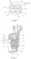
- the angular position measuring device generally includes a device housing 21, a cup-shaped rotor core (i.e., a yoke) 24, and a cylindrical stator core 25.
- the device housing 21 has disposed therein a bearing 23 coupled to a rotary shaft 22 of, for example, a throttle valve of an internal combustion engine (not shown) to be measured in a rotational angle or angular position.
- the rotor core 24 is attached to an end of the rotary shaft 22 by staking.
- the stator core 25 is disposed in the rotor core 24 coaxially therewith.
- the rotor core 24 and the stator core 25 are each made of a magnetic material such as iron.
- the rotor core 24, as clearly shown in Fig. 1, has formed therein diametrically opposed recesses 26 within which magnets 27 are fitted using adhesive, respectively.
- Each of the magnets 27 is made of a cylindrical or plate member which has two opposed ends magnetized to have North and South poles. The magnets 27 are so arranged that the same poles thereof are opposed in a circumferential direction to produce the repellent force in magnetic fields of the magnets 27.
- Semi-circular small air gaps 50 which are diametrically opposed to each other are formed between an inner surface of the rotor core 24 and an outer surface of the stator core 25 except vicinities of the magnets 27 so that the magnetic flux emerging from the North pole of each of the magnets 27 may pass through the stator core 25 from the rotor core 24 and return back to the South pole of the magnets 27 through the rotor core 24.
- the rotor core 24 has air cavities 28 formed in the vicinity of the magnets 27 for avoiding a short of the magnetic flux between each pole of the magnets 27 and the stator core 25, thereby avoiding a reduction in density of the magnetic flux through the stator core 25 to ensure the measurement accuracy of the angular position measuring device.
- a constant sensor gap 29 is formed in the stator core 25 which passes through the center thereof in a diameter direction.
- the sensor gap 29 serves to form therein a parallel magnetic field.
- the stator core 25 is, as can be seen from Fig. 2, made up of two semi-cylindrical members which are held at a given interval away from each other by a resinous spacer 30, thereby defining the sensor gap 29.
- Two Hall ICs 31 are arrayed adjacent to each other within the sensor gap 29. Each of the Hall ICs 31 has installed therein a magnetic sensor and an amplifier and works to produce a voltage signal as a function of the density of a magnetic flux passing therethrough.
- Each of the Hall ICs 31 may have functions of output gain adjustment, offset adjustment, electrically trimming a temperature characteristic-correcting program using an external device, and self-diagnosing a breakage and short of an electric circuit.
- the Hall ICs 31 are positioned by the spacer 30 and have terminals which pass through the spacer 30 and are welded to connector pins 32.
- the connector pin 32, the stator core 24, and the spacer 30 are installed in a connector housing 33 which is molded from a resinous material.
- the connector housing 33 has formed in a left surface, as viewed in Fig. 2, an annular groove 34 into which the end of the device housing 21 is press-fitted and bonded, thereby holding a coaxial relation between the rotor core 24 and the stator core 25.
- the two magnets 27 are, as described above, so arranged in diametrically opposed portions of the rotor core 24 as to produce the repellent force in the magnetic fields thereof.
- the magnetic flux emerging from the North pole of each of the magnets 27, thus, goes to the stator core 25 through the rotor core 24 to the sensor gap 29 (i.e., the Hall ICs 31) and back to the rotor core 24 through the stator core 25 and enters the South pole of the magnet 27.
- the sensor gap 29 i.e., the Hall ICs 31
- each of the Hall ICs 31 produce a voltage output proportional to the rotational angle of the rotor core 24.
- the determination of the rotational angle or angular position of the rotor core 24 is made using two voltage outputs from the Hall ICs 31. For example, if a difference between the two voltage outputs exceeds a given value, it may be concluded that some failure has occurred in the angular position measuring device.
- the installation of the two magnets 27 in the diametrically opposed portions of the rotor core 24 in such a manner that the same poles are opposed to each other in a circumferential direction of the rotor core 24 eliminates the need for an air gap, like the one shown in Fig. 19, between the pole surfaces of the magnets 27 and the periphery of the stator core 25, thereby increasing the degree of freedom of design of the magnets 27 which allows each of the magnets 27 to be formed by a plate or cylindrical member that is easy to manufacture and magnetize. This also results in a decrease in error of outputs of the Hall ICs 31, thus increasing the accuracy in determining the angular position of the rotary shaft 22. Further, the arrangement of the magnets 27 in this embodiment eliminates the need for installation of the magnets 27 on an inner peripheral surface of the rotor core 24, thereby allowing the rotor core 24 to be reduced in size in the radius direction thereof.
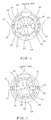
- Fig. 4 shows an angular position measuring device according to the second embodiment of the invention.
- the magnets 27 are so installed in the rotor core 24 that a circumferential distance between the North poles of the magnets 27 is greater than that between the South poles. Of course, the circumferential distance between the South poles of the magnets 27 may be greater than that between the North poles.
- the air cavities 28 serving to avoid a short of the magnetic flux between each pole of the magnets 27 and the stator core 25 extend longer than in the first embodiment. Other arrangements are identical with those in the first embodiment, and explanation thereof in detail will be omitted here.
- the magnetic flux density increases and decreases symmetrically as a function of a rotational angle of the rotor core 24, however, the invention is not always limited to such a geometrical relation.
- each path of the magnetic flux using one of the magnets 27, however, may employ a plurality of magnets which are so arrayed that the North pole of one of the magnets is in contact with the South pole of an adjacent one for strengthening the magnetic field.
- three or more magnets may be so installed in the rotor core 24 at given intervals that adjacent two of the magnets produce a repellent force.
- the Hall ICs 31 are disposed in an area through which the magnetic fluxes produced by adjacent two of the magnets pass in parallel.
- the shape of the magnets 27 is not limited to a cylindrical or flat one and may be determined in view of an installation place or ease of manufacture.
- the magnets 27 may be different in size from each other.
- Fig. 5 shows an angular position measuring device according to the third embodiment of the invention.
- the same reference numbers as employed in the first embodiment refer to the same parts, and explanation thereof in detail will be omitted here.
- a rotary lever 41 is molded from a resinous material and has formed integrally therein the rotor core 24 within which two magnets 27 are installed.
- the rotary lever 41 is coupled to an object to be measured in angular position and has a cavity within which the stator core 25 is fitted in contact with an inner wall (i.e., a bearing surface) of the cavity so that the rotary lever 41 may rotate in synchronization with the object.
- a coil spring 43 is connected at one end to an inner wall of a cylindrical cover 49 and at the other end to the rotary lever 41 so that upon release of torque transmitted from the object, the rotary lever 41 is returned back to an angular null position.
- a shaft 45 made of a non-magnetic material is fitted in a recess formed in the center of an end surface of the stator core 25.
- the shaft passes through a hole 46 formed in the rotary lever 41.
- a stopper plate 47 is fitted in a groove formed in the head of the shaft 45 to prevent the rotary lever 45 from being dislodged from the shaft 45 (i.e., the stator core 25).
- a spring washer 48 is disposed between the stopper plate 47 and the rotary lever 41 to minimize the thrust of the rotary lever 41.
- the connector housing 33 is formed integrally with the cover 49.
- the cover 49 has disposed therein the rotary lever 41 and the rotor core 24.
- the magnets 27 are, like the first embodiment, so arranged in diametrically opposed portions of the rotor core 24 as that the magnetic flux emerging from the North pole of each of the magnets 27 goes to the stator core 25 through the rotor core 24 to the sensor gap 29 (i.e., the Hall ICs 31) and back to the rotor core 24 through the stator core 25 and enters the South pole of the magnet 27.
- Other arrangements are identical with those in the first embodiment.
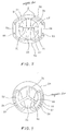
- Fig. 6 shows an angular position measuring device according to the fourth embodiment of the invention which is different from the first and second embodiments in that the stator core 25 has formed therein air cavities 51 that are oval in cross section. Other arrangements are identical, and explanation thereof in detail will be omitted here.
- the air cavities 51 are formed in diametrically opposed peripheral portions of the stator core 25 so that they communicate with ends of the sensor gap 29, respectively.
- the formation of the air cavities 51 causes the magnetic flux produced by each of the magnets 27 to concentrate at the center of the stator core 25, that is, the Hall ICs 31 installed in the sensor gap 29, thus resulting in an increase in density of the magnetic flux passing through the Hall ICs 31.
- This increase will result in an increase in output of the Hall ICs 31, thereby allowing an amplification factor of an output from each of the Hall ICs 31 to be decreased.
- the decreasing of the amplification factor will minimize undesirable effects of a change in temperature of the Hall ICs 31 on outputs of the Hall ICs 31 and also allows the amplifier installed in each of the Hall ICs 31 to be simplified in circuit structure.
- Each of the air cavities 51 communicates with the air cavities 28 through a slit 60 formed in the periphery of the stator core 25, thereby providing as wide an outer surface of the stator core 25 into which the magnetic flux enters as possible. This causes a greater magnetic flux from the rotor core 24 to enter the stator core 25, thus increasing the outputs of the Hall ICs 31.
- Fig. 7 shows an angular position measuring device according to the fifth embodiment of the invention which is different from the fourth embodiment only in that the air gap 50 is formed to be constant in width without forming the air cavities 28 in the rotor core 24.
- Other arrangements are identical, and explanation thereof in detail will be omitted here.
- the air cavities 51 which are formed in diametrically opposed peripheral portions of the stator core 25, like the fourth embodiment, serve to concentrate the magnetic flux produced by each of the magnets 27 at the sensor gap 29, thus resulting in an increase in density of the magnetic flux passing through the Hall ICs 31 and also work to avoid a short of the magnetic flux between each pole of the magnets 27 and the stator core 25.
- Fig. 8 shows an angular position measuring device according to the sixth embodiment of the invention which is different from the first to fifth embodiments in that a rotor core 52 is made of a cylindrical member that is oval or elliptical in cross section. Other arrangements are identical, and explanation thereof in detail will be omitted here.
- the rotor core 52 has formed in its ends in a longitudinal direction thereof recesses 53 within which magnets 54 are fitted using adhesive, respectively.
- the air gap 50 between the rotor core 52 and the stator core 25 increases in volume as approaching each of the magnets 54 (i.e., each pole of the magnets 54), thereby defining a greater air cavity around each of the magnets 54 which serves, like the air cavities 28, to avoid a short of the magnetic flux between one of poles of the magnets 54 and the stator core 25.
- the air gap 50 decreases in volume gradually as leaving from each of the magnets 54, thereby preventing the magnetic flux from the inner surface of the rotor core 52 to the outer surface of the stator core 25 from being biased toward each of the magnets 54, thus resulting in uniformity of the magnetic flux entering the stator core 25.
- This improves the linearity of a change in density of the magnetic flux in the sensor gap 29 with a change in rotational angle of the rotor core 52.
- Fig. 9 shows an angular position measuring device according to the seventh embodiment of the invention.
- the angular position measuring devices of the first to sixth embodiments are so designed that the density of a magnetic flux passing through the sensor gap 29 increases and decreases in a cycle of 180° (see Fig. 3) and, thus, have an effective angular position-measuring range of 180° or less within which an output of each of the Hall ICs 31 changes linearly.
- the angular position measuring device of this embodiment is so designed as to have a wider angular position-measuring range over 180° .
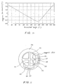
- the stator core 55 is made up of three parts which are assembled to define three sensor gaps 56 which extend radially from the center thereof at an angular interval of 120° .
- the Hall IC 31 is disposed within one of the sensor gaps 56.
- Two magnets 27 are installed in the rotor core 24 at an angular interval of 120° which is equal to that of the sensor gaps 56.
- the rotor core 24 has two air cavities 28 formed in the vicinity of the magnets 27 for avoiding a short of the magnetic flux between each pole of the magnets 27 and the stator core 25.
- Other arrangements are identical with those of the first embodiment, and explanation thereof in detail will be omitted here.
- the magnetic flux emerging from the North pole of a right one of the magnets 27 goes to an upper right portion of the stator core 55 through the rotor core 24 to a right one of the sensor gaps 56 (i.e., the Hall IC 31) and back to the rotor core 24 through a lower right portion of the stator core 55 and enters the South pole of the right magnet 27.
- the magnetic flux emerging from the North pole of a left one of the magnets 27 goes to an upper left portion of the stator core 55 through the rotor core 24 to a left one of the sensor gaps 56 and back to the rotor core 24 through a lower left portion of the stator core 55 and enters the South pole of the left magnet 27.
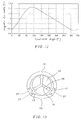
- the rotor core 24 When the rotor core 24 starts to rotate, it will cause the density of magnetic flux through each of the right and left sensor gaps 56 of the stator core 55 to decrease, as shown in Fig. 10, as a function of a rotational angle of the rotor core 24 within a range of approximately 0° to 230° and then increase as a function of a rotational angle of the rotor core 24 within a range of approximately 240° to 350° .
- the range within which the density of magnetic flux passing through the Hall IC 31 decreases linearly is asymmetrical with, that is, wider than the range within which the density of magnetic flux passing through the Hall IC 31 increases linearly, thereby enabling the angular position measuring device of this embodiment to produce an output which changes linearly as a function of a rotational angle of the rotor core 24 over an angular range of approximately 220° .
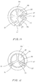
- Fig. 11 shows an angular position measuring device according to the eighth embodiment of the invention which is different from the seventh embodiment in that the stator core 55 is made up of four parts which are assembled to form four sensor gaps 56 which extend radially from the center thereof at an angular interval of 90°, and two magnets 27 are installed in the rotor core 24 at an angular interval of 90° .
- the stator core 55 is made up of four parts which are assembled to form four sensor gaps 56 which extend radially from the center thereof at an angular interval of 90°
- two magnets 27 are installed in the rotor core 24 at an angular interval of 90° .
- Other arrangements are identical, and explanation thereof in detail will be omitted here.
- the magnetic flux emerging from the North pole of a right one of the magnets 27 goes to an upper right portion of the stator core 55 through the rotor core 24 to a right one of the sensor gaps 56 within which the Hall IC 31 is installed and back to the rotor core 24 through a lower right portion of the stator core 55 and enters the South pole of the right magnet 27.
- the magnetic flux emerging from the North pole of the lower magnet 27 goes to a lower left portion of the stator core 55 through the rotor core 24 to the lower sensor gap 56 and back to the rotor core 24 through a lower right portion of the stator core 55 and enters the South pole of the lower magnet 27.
- the angular position measuring device of this embodiment is capable of producing an output which changes, as shown in Fig. 12, linearly as a function of a rotational angle of the rotor core 24 over an angular range of approximately 200° .
- Fig. 13 shows an angular position measuring device according to the ninth embodiment of the invention which is a modification of the one shown in Fig. 9.
- the stator core 55 has three air cavities 57, like the air cavities 51 shown in Figs. 6, 7, and 8, which are oval in cross section and which serve to concentrate the magnetic flux on the Hall IC 31 installed in one of the sensor gaps 56.
- the air gap 50 between the rotor core 24 and the stator core 55 increases in volume as approaching each of the magnets 27, thereby defining a greater air cavity around each of the magnets 27 which serves, like the air cavities 28, to avoid a short of the magnetic flux between one of poles of the magnets 27 and the stator core 55.
- Fig. 14 shows an angular position measuring device which is a modification of the one shown in Fig. 11.
- the stator core 55 has four air cavities 57, like the air cavities 51 shown in Figs. 6, 7, and 8, which are oval in cross section and which serve to concentrate the magnetic flux at the Hall IC 31 installed in one of the sensor gaps 56.
- the air gap 50 between the rotor core 24 and the stator core 55 increases in volume as approaching each of the magnets 27, thereby defining a greater air cavity around each of the magnets 27 which serves, like the air cavities 28, to avoid a short of the magnetic flux between one of poles of the magnets 27 and the stator core 55.
- the air gap 50 decreases in volume gradually as leaving from each of the magnets 54, thereby preventing the magnetic flux from the inner surface of the rotor core 52 to the outer surface of the stator core 25 from being biased toward each of the magnets 54, thus resulting in uniformity of the magnetic flux entering the stator core 25.
- This improves the linearity of a change in density of the magnetic flux in the sensor gap 29 with a change in rotational angle of the rotor core 52.
- Fig. 15 shows an angular position measuring device which is a modification of the one shown in Fig. 13.
- the stator core 55 is formed coaxially with the rotor core 24 so as to form a constant air gap 50 between the stator core 55 and the rotor core 24.
- Other arrangements are identical with those in Fig. 13, and explanation thereof in detail will be omitted here.
- Fig. 16 shows an angular position measuring device which is a modification of the one shown in Fig. 14.
- the stator core 55 is formed coaxially with the rotor core 24 so as to form a constant air gap 50 between the stator core 55 and the rotor core 24.
- Other arrangements are identical with those in Fig. 14, and explanation thereof in detail will be omitted here.
- the sensor gaps 56 in the seventh to ninth embodiments are formed at regular angular intervals, they may alternatively be arranged at irregular angular intervals depending upon a desired angular position-measuring range. Further, the angular interval between the two magnets 27 may be different from that of the air gaps 56. In this case, the same effects as provided by the seventh to ninth embodiments are obtained by modifying the location and/or the shape of the magnetic flux short-avoiding air cavities 28 formed in the rotor core 24 as needed.
- Fig. 17 shows an angular position measuring device according to the tenth embodiment of the invention.
- the angular position measuring device of each of the first to sixth embodiments the sensor gap 29 extends over a diameter of the stator core 25 and has a length sufficient to array the two Hall ICs 31.
- the angular position measuring device in each of the seventh to ninth embodiments has formed therein more than two sensor gaps whose length is equal to the radius of the stator core 25 and may be insufficient to array two Hall ICs if the stator core 25 is decreased in size for compactness of the device.
- the angular position measuring device of the tenth embodiment makes a stator core of three or more parts so as to form at least one air gap longer than the radius of the stator core.
- the stator core 61 is made up of three parts so as to define two shorter air gaps 64 and one longer air gap 62.
- the air gaps 64 are aligned with each other horizontally, as viewed in the drawing.
- Upper two of the three parts of the stator core 61 are symmetrical so as to have the air gap 64 pass through the center of the stator core 61.
- the air gap 64 thus, has the length longer than the radius of the stator core which is sufficient to array two Hall ICs 31.
- Two magnets 27 are so arranged in the rotor core 24 that when one of the magnets 27 face an end of one of the air gaps 64, the other magnet 27 face a diametrically opposed end of the other air gap 64. Cavities like the air cavities 51 as shown in Figs. 6, 7, and 8 may be formed in the air gaps 64.
- Fig. 18 shows an angular position measuring device which is a modified form of the one shown in Fig. 17 and different therefrom only in that two air gaps 64 inclined downward, as viewed in the drawing, without being aligned with each other.
- This structure also provides the same effects as in the above tenth embodiment.
- the two Hall ICs 31 may be laid to overlap each other in parallel to the magnetic flux in the sensor gap 29.
- a single Hall IC may be used or three or more Hall ICs may be arrayed in parallel or perpendicular to the magnetic flux depending upon the size of the sensor gap 29.
- magnetoresistive elements may be employed.
- the rotor core 24 or 52 in the above embodiments is installed in the device housing 21 to be rotatable in synchronism with rotation of the rotary shaft 22, however, it may be secured to the device housing 21 to be stationary, while the inner core 25, 55, or 61 may be retained by the connector housing 33 to be rotatable following rotation of the rotary shaft 22.
- a compact and high-accuracy angular position measuring device which has magnets installed in a rotor core and a magnetic sensor installed in a stator core.
- the magnetic sensor produces an output indicative of an angular position of the rotor core as a function of a change in density of magnetic flux produced by the magnets.
- the magnets are so arranged in the rotor core that the same poles are opposed magnetically to produce a repellent force in magnetic fields of the magnets, thereby causing the magnetic flux to go to the magnetic sensor through the rotor core.
Landscapes
- Physics & Mathematics (AREA)
- General Physics & Mathematics (AREA)
- Transmission And Conversion Of Sensor Element Output (AREA)
- Measurement Of Length, Angles, Or The Like Using Electric Or Magnetic Means (AREA)
Applications Claiming Priority (6)
| Application Number | Priority Date | Filing Date | Title |
|---|---|---|---|
| JP2000021822 | 2000-01-26 | ||
| JP2000021822 | 2000-01-26 | ||
| JP2000053927 | 2000-02-29 | ||
| JP2000053927 | 2000-02-29 | ||
| JP2000117703A JP3596667B2 (ja) | 2000-01-26 | 2000-04-19 | 回転角検出装置 |
| JP2000117703 | 2000-04-19 |
Publications (3)
| Publication Number | Publication Date |
|---|---|
| EP1120626A2 true EP1120626A2 (de) | 2001-08-01 |
| EP1120626A3 EP1120626A3 (de) | 2002-08-14 |
| EP1120626B1 EP1120626B1 (de) | 2011-06-08 |
Family
ID=27342187
Family Applications (1)
| Application Number | Title | Priority Date | Filing Date |
|---|---|---|---|
| EP01101719A Expired - Lifetime EP1120626B1 (de) | 2000-01-26 | 2001-01-25 | Vorrichtung zur Bestimmung der Winkelposition |
Country Status (3)
| Country | Link |
|---|---|
| US (1) | US6476600B2 (de) |
| EP (1) | EP1120626B1 (de) |
| JP (1) | JP3596667B2 (de) |
Cited By (7)
| Publication number | Priority date | Publication date | Assignee | Title |
|---|---|---|---|---|
| EP1403620A3 (de) * | 2002-09-30 | 2004-04-07 | Denso Corporation | Drehwinkelsensor mit einem erweitertem detektierbarem Winkelbereich |
| FR2859276A1 (fr) * | 2003-08-29 | 2005-03-04 | Denso Corp | Dispositif de determination de position angulaire a detecteur d'anomalie de fonctionnement |
| EP1541035A1 (de) * | 2003-12-09 | 2005-06-15 | Solae, Llc | Sojaproteinkonzentrat mit hoher Gelfestigkeit und Verfahren zur Herstellung |
| WO2005083366A1 (fr) * | 2004-02-11 | 2005-09-09 | Valeo Systemes De Contrôle Moteur | Capteur magnetique de position angulaire |
| US7378840B2 (en) | 2001-12-05 | 2008-05-27 | Aisin Seiki Kabushiki Kaisha | Holding structure of an electronic component and a method for holding the same |
| EP1471290A3 (de) * | 2003-04-23 | 2008-08-20 | Aisin Aw Co., Ltd. | Fehlererkennungsvorrichtung für Drehwinkelsensor |
| EP2330379A4 (de) * | 2008-09-17 | 2014-11-19 | United Automotive Elect Sys Co | Winkelpositionssensor |
Families Citing this family (44)
| Publication number | Priority date | Publication date | Assignee | Title |
|---|---|---|---|---|
| WO2001044757A1 (en) * | 1999-12-14 | 2001-06-21 | Matsushita Electric Industrial Co., Ltd. | Noncontact position sensor |
| FR2821668B1 (fr) * | 2001-03-02 | 2003-05-02 | Moving Magnet Tech | Capteur de position, notamment destine a la detection de la torsion d'une colonne de direction |
| JP3726698B2 (ja) * | 2001-04-19 | 2005-12-14 | アイシン精機株式会社 | 角度センサ |
| US6693424B2 (en) * | 2001-06-08 | 2004-02-17 | Denso Corporation | Magnetic rotation angle sensor |
| US6823270B1 (en) | 2001-06-20 | 2004-11-23 | Curtis Roys | Fluid flow monitoring system |
| US6850849B1 (en) | 2001-06-20 | 2005-02-01 | Curtis Roys | Fluid flow monitor and control system |
| JP3775257B2 (ja) * | 2001-07-30 | 2006-05-17 | アイシン精機株式会社 | 角度センサ |
| DE10202309A1 (de) * | 2002-01-23 | 2003-07-31 | Bosch Gmbh Robert | Wegsensor mit magnetoelektrischem Wandlerelement |
| TW567333B (en) * | 2002-09-20 | 2003-12-21 | Benq Corp | Method for phase matching by detecting magnetic flux |
| JP3913657B2 (ja) * | 2002-10-02 | 2007-05-09 | 株式会社日本自動車部品総合研究所 | トルクセンサ |
| US20040174159A1 (en) * | 2003-03-05 | 2004-09-09 | Claudia Ramirez | Securement feature for rotary position sensor |
| JP4233920B2 (ja) * | 2003-05-15 | 2009-03-04 | 株式会社デンソー | 回転角度検出装置 |
| US20050039564A1 (en) * | 2003-08-20 | 2005-02-24 | Jiyuan Ouyang | Pedal assembly for a vehicle including a non-contact position sensor |
| JP4045230B2 (ja) * | 2003-11-04 | 2008-02-13 | 三菱電機株式会社 | 非接触式回転角度検出装置 |
| JP2005233768A (ja) | 2004-02-19 | 2005-09-02 | Mitsubishi Electric Corp | 回転角検出装置 |
| US7882852B2 (en) * | 2004-05-04 | 2011-02-08 | Woodward Hrt, Inc. | Direct drive servovalve device with redundant position sensing and methods for making the same |
| JP4891070B2 (ja) * | 2004-05-28 | 2012-03-07 | 株式会社ミクニ | アクセル操作装置 |
| JP4433886B2 (ja) * | 2004-06-02 | 2010-03-17 | 株式会社デンソー | 回転角度検出装置 |
| DE102004062098A1 (de) * | 2004-12-23 | 2006-07-13 | Pierburg Gmbh | Stelleinrichtung |
| JP4354397B2 (ja) * | 2004-12-27 | 2009-10-28 | 富士通株式会社 | 磁気力顕微鏡用の磁界発生装置 |
| US7772836B2 (en) * | 2005-04-18 | 2010-08-10 | Ntn Corporation | Device for detecting absolute angle of multiple rotation and angle detection method |
| EP1744136B1 (de) * | 2005-07-11 | 2009-05-06 | NCTEngineering GmbH | Drehwinkelsensor |
| JP4046746B2 (ja) | 2005-10-20 | 2008-02-13 | 三菱電機株式会社 | 回転角検出装置 |
| JP4716106B2 (ja) * | 2005-11-15 | 2011-07-06 | アイシン精機株式会社 | 回転角検出装置 |
| JP4294036B2 (ja) | 2006-03-29 | 2009-07-08 | 三菱電機株式会社 | 回転角検出装置 |
| US7463022B2 (en) * | 2006-08-14 | 2008-12-09 | Delphi Technologies, Inc. | Position sensor system with magnetically anisotropic flux guide |
| JP4978774B2 (ja) * | 2006-11-08 | 2012-07-18 | アイシン精機株式会社 | 回転角検出装置の実装構造 |
| KR100789422B1 (ko) | 2006-11-16 | 2007-12-28 | 주식회사 컴씨스 | 독립 스위치가 구비된 비접촉식 회전변위센서 |
| DE102007013755B4 (de) * | 2007-03-22 | 2020-10-29 | Te Connectivity Germany Gmbh | Indikatorelement für einen magnetischen Drehwinkelgeber |
| US7639004B2 (en) * | 2007-07-23 | 2009-12-29 | Gm Global Technology Operations, Inc. | Apparatus for sensing angular displacement between first and second rotating shafts including flux collectors |
| US7893689B2 (en) | 2007-10-03 | 2011-02-22 | Denso Corporation | Displacement measuring device |
| JP4638523B2 (ja) * | 2008-05-09 | 2011-02-23 | 愛三工業株式会社 | スロットル開度検出装置の製造方法 |
| KR100986007B1 (ko) | 2008-10-13 | 2010-10-06 | 대성전기공업 주식회사 | 회동 각도 검출을 위한 마그네틱 위치 센서 |
| CN102472636B (zh) * | 2009-07-15 | 2015-06-24 | Skf私人有限公司 | 霍尔效应感应装置 |
| US8773116B2 (en) | 2010-09-03 | 2014-07-08 | Panasonic Corporation | Rotation angle detecting device |
| DE102011006035A1 (de) * | 2011-03-24 | 2012-09-27 | Robert Bosch Gmbh | Weggeber und zugehörige Pedaleinheit |
| US9052029B2 (en) * | 2011-12-12 | 2015-06-09 | Hyundai Motor Company | Apparatus and method for controlling actuator that controls opening and closing of intake valve |
| JP5720961B2 (ja) * | 2012-12-27 | 2015-05-20 | 株式会社デンソー | 位置検出装置 |
| JP5757285B2 (ja) * | 2012-12-27 | 2015-07-29 | 株式会社デンソー | 位置検出装置 |
| CN107923763B (zh) * | 2015-08-31 | 2020-11-06 | 日立汽车系统株式会社 | 位置传感器以及靶标 |
| JP6535270B2 (ja) * | 2015-10-30 | 2019-06-26 | ヒロセ電機株式会社 | 回転検出装置 |
| US10819263B2 (en) * | 2016-12-14 | 2020-10-27 | Sew-Eurodrive Gmbh & Co. Kg | Method for determining the angular position of the rotor of an inverter-fed synchronous motor, and an apparatus for carrying out the method |
| CN111141316A (zh) * | 2020-01-15 | 2020-05-12 | 苏州汇川技术有限公司 | 磁编码器模块、磁编码器以及伺服电机 |
| DE102021105566A1 (de) | 2020-03-24 | 2021-09-30 | Honeywell International Inc. | Drehgeber |
Citations (1)
| Publication number | Priority date | Publication date | Assignee | Title |
|---|---|---|---|---|
| JPH0972706A (ja) | 1995-09-04 | 1997-03-18 | Nissan Motor Co Ltd | 角度センサ |
Family Cites Families (11)
| Publication number | Priority date | Publication date | Assignee | Title |
|---|---|---|---|---|
| FR1375070A (fr) * | 1963-07-05 | 1964-10-16 | Csf | Appareils électriques tournants à effet hall |
| FR2670286B1 (fr) | 1990-12-05 | 1993-03-26 | Moving Magnet Tech | Capteur magnetique de position et de vitesse a sonde de hall. |
| FR2715726B1 (fr) | 1994-02-01 | 1996-10-18 | Moving Magnet Tech | Capteur magnétique de position à sonde de Hall. |
| US5789917A (en) * | 1990-12-05 | 1998-08-04 | Moving Magnet Technologie Sa | Magnetic position sensor with hall probe formed in an air gap of a stator |
| JPH0926304A (ja) * | 1995-07-12 | 1997-01-28 | Hitachi Metals Ltd | 永久磁石式回転角検出器 |
| DE19630764A1 (de) * | 1995-09-29 | 1997-04-03 | Bosch Gmbh Robert | Meßvorrichtung zur berührungslosen Erfassung einer Relativbewegung |
| DE19634282A1 (de) | 1996-08-24 | 1998-02-26 | Bosch Gmbh Robert | Meßvorrichtung zur berührungslosen Erfassung eines Drehwinkels |
| DE19634281C2 (de) * | 1996-08-24 | 2000-01-27 | Bosch Gmbh Robert | Meßvorrichtung zur berührungslosen Erfassung eines Drehwinkels bzw. einer linearen Bewegung |
| DE19726691A1 (de) * | 1997-06-24 | 1999-01-07 | Itt Mfg Enterprises Inc | Drehwinkelsensor mit einem asymmetrisch angeordneten Permanentmagneten |
| JP3438064B2 (ja) | 1997-09-11 | 2003-08-18 | 帝国通信工業株式会社 | 回転角度センサ |
| JP3491596B2 (ja) * | 1999-06-28 | 2004-01-26 | 株式会社デンソー | 回転角検出装置 |
-
2000
- 2000-04-19 JP JP2000117703A patent/JP3596667B2/ja not_active Expired - Lifetime
-
2001
- 2001-01-25 EP EP01101719A patent/EP1120626B1/de not_active Expired - Lifetime
- 2001-01-26 US US09/769,517 patent/US6476600B2/en not_active Expired - Lifetime
Patent Citations (1)
| Publication number | Priority date | Publication date | Assignee | Title |
|---|---|---|---|---|
| JPH0972706A (ja) | 1995-09-04 | 1997-03-18 | Nissan Motor Co Ltd | 角度センサ |
Cited By (11)
| Publication number | Priority date | Publication date | Assignee | Title |
|---|---|---|---|---|
| US7378840B2 (en) | 2001-12-05 | 2008-05-27 | Aisin Seiki Kabushiki Kaisha | Holding structure of an electronic component and a method for holding the same |
| DE10256709B4 (de) * | 2001-12-05 | 2011-05-05 | Aisin Seiki K.K., Kariya | Haltestruktur für eine elektronische Komponente und Verfahren zum Herstellen einer Haltestruktur für eine elektronische Komponente |
| EP1403620A3 (de) * | 2002-09-30 | 2004-04-07 | Denso Corporation | Drehwinkelsensor mit einem erweitertem detektierbarem Winkelbereich |
| US7071683B2 (en) | 2002-09-30 | 2006-07-04 | Nippon Soken, Inc. | Rotation angle sensing device having enlarged detectable angle range |
| EP1471290A3 (de) * | 2003-04-23 | 2008-08-20 | Aisin Aw Co., Ltd. | Fehlererkennungsvorrichtung für Drehwinkelsensor |
| FR2859276A1 (fr) * | 2003-08-29 | 2005-03-04 | Denso Corp | Dispositif de determination de position angulaire a detecteur d'anomalie de fonctionnement |
| US7227353B2 (en) | 2003-08-29 | 2007-06-05 | Denso Corporation | Angular position determining apparatus with malfunction detector |
| EP1541035A1 (de) * | 2003-12-09 | 2005-06-15 | Solae, Llc | Sojaproteinkonzentrat mit hoher Gelfestigkeit und Verfahren zur Herstellung |
| WO2005083366A1 (fr) * | 2004-02-11 | 2005-09-09 | Valeo Systemes De Contrôle Moteur | Capteur magnetique de position angulaire |
| US8143883B2 (en) | 2004-02-11 | 2012-03-27 | Valeo Systemes De Controle Moteur | Magnetic angular-position sensor |
| EP2330379A4 (de) * | 2008-09-17 | 2014-11-19 | United Automotive Elect Sys Co | Winkelpositionssensor |
Also Published As
| Publication number | Publication date |
|---|---|
| JP3596667B2 (ja) | 2004-12-02 |
| US20010009366A1 (en) | 2001-07-26 |
| EP1120626B1 (de) | 2011-06-08 |
| EP1120626A3 (de) | 2002-08-14 |
| JP2001317909A (ja) | 2001-11-16 |
| US6476600B2 (en) | 2002-11-05 |
Similar Documents
| Publication | Publication Date | Title |
|---|---|---|
| US6476600B2 (en) | Angular position measuring device | |
| US5861745A (en) | Measuring device for contactless determination of relative angular position with an improved linear range | |
| US6356073B1 (en) | Angular position detecting apparatus configured for concentrating magnetic flux into detecting portion | |
| US6576890B2 (en) | Linear output non-contacting angular position sensor | |
| US6232771B1 (en) | Device for contactless measurement of angle of rotation of linear motion between rotor and stator composed of a plurality of parts | |
| US6188216B1 (en) | Low profile non-contacting position sensor | |
| US6323641B1 (en) | Non-contacting position sensor with helical flux linkage | |
| JP3455706B2 (ja) | テーパー付きの二極の磁石を用いる非接触式のポジションセンサ | |
| US9207100B2 (en) | Magnetic position sensor with field direction measurement and flux collector | |
| US7259554B2 (en) | Angle position sensor with inner and outer magnetic rings | |
| JP4169536B2 (ja) | アクチュエータ | |
| JPH09329461A (ja) | 検出装置 | |
| JP5944703B2 (ja) | 回転角度検出装置 | |
| US20070108968A1 (en) | Rotation angle detection device | |
| JPH11211410A (ja) | 非接触型位置センサ | |
| JP2002542473A (ja) | 回転角を無接触方式で検出するための測定装置 | |
| JP2009047426A (ja) | 非接触式回転角度検出センサ | |
| JP2001510576A (ja) | 回転角を無接触で検出する測定装置 | |
| US20050116706A1 (en) | Angle sensor | |
| CA1232957A (en) | Rotational sensor | |
| JP3438692B2 (ja) | 回転角検出装置 | |
| JPH02298815A (ja) | 回転角度センサ | |
| JP3061225B2 (ja) | 磁電変換型回転角センサ | |
| US7012422B2 (en) | Non-contact type position sensor | |
| JP3422184B2 (ja) | 磁気式回転角度センサ |
Legal Events
| Date | Code | Title | Description |
|---|---|---|---|
| PUAI | Public reference made under article 153(3) epc to a published international application that has entered the european phase |
Free format text: ORIGINAL CODE: 0009012 |
|
| AK | Designated contracting states |
Kind code of ref document: A2 Designated state(s): AT BE CH CY DE DK ES FI FR GB GR IE IT LI LU MC NL PT SE TR |
|
| AX | Request for extension of the european patent |
Free format text: AL;LT;LV;MK;RO;SI |
|
| PUAL | Search report despatched |
Free format text: ORIGINAL CODE: 0009013 |
|
| AK | Designated contracting states |
Kind code of ref document: A3 Designated state(s): AT BE CH CY DE DK ES FI FR GB GR IE IT LI LU MC NL PT SE TR |
|
| AX | Request for extension of the european patent |
Free format text: AL;LT;LV;MK;RO;SI |
|
| 17P | Request for examination filed |
Effective date: 20021031 |
|
| AKX | Designation fees paid |
Designated state(s): DE FR GB |
|
| 17Q | First examination report despatched |
Effective date: 20080508 |
|
| GRAP | Despatch of communication of intention to grant a patent |
Free format text: ORIGINAL CODE: EPIDOSNIGR1 |
|
| GRAC | Information related to communication of intention to grant a patent modified |
Free format text: ORIGINAL CODE: EPIDOSCIGR1 |
|
| GRAS | Grant fee paid |
Free format text: ORIGINAL CODE: EPIDOSNIGR3 |
|
| GRAA | (expected) grant |
Free format text: ORIGINAL CODE: 0009210 |
|
| AK | Designated contracting states |
Kind code of ref document: B1 Designated state(s): DE FR GB |
|
| REG | Reference to a national code |
Ref country code: GB Ref legal event code: FG4D |
|
| REG | Reference to a national code |
Ref country code: DE Ref legal event code: R096 Ref document number: 60144737 Country of ref document: DE Effective date: 20110721 |
|
| PLBE | No opposition filed within time limit |
Free format text: ORIGINAL CODE: 0009261 |
|
| STAA | Information on the status of an ep patent application or granted ep patent |
Free format text: STATUS: NO OPPOSITION FILED WITHIN TIME LIMIT |
|
| 26N | No opposition filed |
Effective date: 20120309 |
|
| REG | Reference to a national code |
Ref country code: DE Ref legal event code: R097 Ref document number: 60144737 Country of ref document: DE Effective date: 20120309 |
|
| REG | Reference to a national code |
Ref country code: FR Ref legal event code: PLFP Year of fee payment: 15 |
|
| REG | Reference to a national code |
Ref country code: FR Ref legal event code: PLFP Year of fee payment: 16 |
|
| REG | Reference to a national code |
Ref country code: FR Ref legal event code: PLFP Year of fee payment: 17 |
|
| REG | Reference to a national code |
Ref country code: FR Ref legal event code: PLFP Year of fee payment: 18 |
|
| PGFP | Annual fee paid to national office [announced via postgrant information from national office to epo] |
Ref country code: DE Payment date: 20200121 Year of fee payment: 20 Ref country code: GB Payment date: 20200123 Year of fee payment: 20 |
|
| PGFP | Annual fee paid to national office [announced via postgrant information from national office to epo] |
Ref country code: FR Payment date: 20200121 Year of fee payment: 20 |
|
| REG | Reference to a national code |
Ref country code: DE Ref legal event code: R071 Ref document number: 60144737 Country of ref document: DE |
|
| REG | Reference to a national code |
Ref country code: GB Ref legal event code: PE20 Expiry date: 20210124 |
|
| PG25 | Lapsed in a contracting state [announced via postgrant information from national office to epo] |
Ref country code: GB Free format text: LAPSE BECAUSE OF EXPIRATION OF PROTECTION Effective date: 20210124 |