EP1120793A1 - Structure de support pour un réseau modifiable de combustible d'un réacteur nucléaire à eau bouillante - Google Patents
Structure de support pour un réseau modifiable de combustible d'un réacteur nucléaire à eau bouillante Download PDFInfo
- Publication number
- EP1120793A1 EP1120793A1 EP00300522A EP00300522A EP1120793A1 EP 1120793 A1 EP1120793 A1 EP 1120793A1 EP 00300522 A EP00300522 A EP 00300522A EP 00300522 A EP00300522 A EP 00300522A EP 1120793 A1 EP1120793 A1 EP 1120793A1
- Authority
- EP
- European Patent Office
- Prior art keywords
- control rod
- approximately
- support plate
- accordance
- fuel
- Prior art date
- Legal status (The legal status is an assumption and is not a legal conclusion. Google has not performed a legal analysis and makes no representation as to the accuracy of the status listed.)
- Withdrawn
Links
- 239000000446 fuel Substances 0.000 title claims abstract description 80
- XLYOFNOQVPJJNP-UHFFFAOYSA-N water Substances O XLYOFNOQVPJJNP-UHFFFAOYSA-N 0.000 title claims description 7
- 238000009835 boiling Methods 0.000 title description 3
- 230000000712 assembly Effects 0.000 claims abstract description 39
- 238000000429 assembly Methods 0.000 claims abstract description 39
- 230000008859 change Effects 0.000 claims abstract description 13
- 230000000452 restraining effect Effects 0.000 claims abstract description 3
- 238000005192 partition Methods 0.000 claims description 4
- 229910001055 inconels 600 Inorganic materials 0.000 claims description 2
- 238000006243 chemical reaction Methods 0.000 description 4
- 229910052778 Plutonium Inorganic materials 0.000 description 2
- 230000006978 adaptation Effects 0.000 description 2
- 230000008901 benefit Effects 0.000 description 2
- 230000004048 modification Effects 0.000 description 2
- 238000012986 modification Methods 0.000 description 2
- OYEHPCDNVJXUIW-UHFFFAOYSA-N plutonium atom Chemical compound [Pu] OYEHPCDNVJXUIW-UHFFFAOYSA-N 0.000 description 2
- 230000009467 reduction Effects 0.000 description 2
- 229910052770 Uranium Inorganic materials 0.000 description 1
- 238000003491 array Methods 0.000 description 1
- 238000009434 installation Methods 0.000 description 1
- 230000003134 recirculating effect Effects 0.000 description 1
- 238000004064 recycling Methods 0.000 description 1
- 238000004513 sizing Methods 0.000 description 1
- JFALSRSLKYAFGM-UHFFFAOYSA-N uranium(0) Chemical compound [U] JFALSRSLKYAFGM-UHFFFAOYSA-N 0.000 description 1
Images


Classifications
-
- G—PHYSICS
- G21—NUCLEAR PHYSICS; NUCLEAR ENGINEERING
- G21C—NUCLEAR REACTORS
- G21C5/00—Moderator or core structure; Selection of materials for use as moderator
- G21C5/02—Details
- G21C5/10—Means for supporting the complete structure
-
- Y—GENERAL TAGGING OF NEW TECHNOLOGICAL DEVELOPMENTS; GENERAL TAGGING OF CROSS-SECTIONAL TECHNOLOGIES SPANNING OVER SEVERAL SECTIONS OF THE IPC; TECHNICAL SUBJECTS COVERED BY FORMER USPC CROSS-REFERENCE ART COLLECTIONS [XRACs] AND DIGESTS
- Y02—TECHNOLOGIES OR APPLICATIONS FOR MITIGATION OR ADAPTATION AGAINST CLIMATE CHANGE
- Y02E—REDUCTION OF GREENHOUSE GAS [GHG] EMISSIONS, RELATED TO ENERGY GENERATION, TRANSMISSION OR DISTRIBUTION
- Y02E30/00—Energy generation of nuclear origin
- Y02E30/30—Nuclear fission reactors
Definitions
- This invention relates generally to reactor pressure vessels for boiling water reactors and more particularly, to a support structure located within the reactor pressure vessel and a lattice array.
- Light water reactor core configurations should allow for the capability of conversion from uranium to fissionable plutonium and recycling of plutonium.
- the current fuel economy may not justify this capability at the present time, so a configuration which facilitates providing this capability in the future offers a significant advantage.
- a boiling water reactor has an initial core configuration that can be changed to accommodate future requirements for larger, and fewer, fuel assemblies and a reduction in number of control rod drives (CRDs).
- the initial configuration can also be changed to further accommodate fuel conversion made practical with advanced core lattices.
- a reactor core, internal components, and a reactor pressure vessel permit installation of either standard size fuel located on a "conventional” pitch or a size and pitch that is approximately 1.414 or 2.000 times larger.
- the BWR allows conversion from the "conventional" currently used configuration to "future" configurations at any time in the life of the plant.
- the BWR includes an apparatus for supporting fuel assemblies in a substantially cylindrical RPV.
- the apparatus in one embodiment, includes a support plate extending across at least a portion of the RPV and a plurality of CRD housings located in the RPV below the support plate.
- the CRD housings are secured to, and provide support for, the support plate.
- the apparatus further includes a plurality of control rods in communication with the CRD housings, a plurality of flow tubes in communication with the fuel assemblies, and a plurality of control rod guide tubes.
- the fuel assemblies are supported, at least in part, by the control rod guide tubes.
- the support plate supports the weight of the fuel assemblies and the control rod guide tubes by transferring the weight of the fuel assemblies and the control rod guide tubes to the CRD housings.
- the support plate serves as a flow partition forming part of an inlet plenum containing flow and directing the flow up through the flow tubes and then to the fuel assemblies.
- the plenum also includes a bottom head of the RPV, a pump deck, and a seal located between the support plate and the pump deck. The seal permits differential expansion between the support plate and the pump deck.
- the RPV bottom head contains the CRD housings.
- the apparatus has a plurality of fuel support platelets located at one end of the flow tubes and a grid horizontally restraining the fuel support platelets.
- the support plate, the grid, the fuel support platelets, and the flow tubes are capable of being replaced in order to accommodate a change to a different lattice array configuration.
- Each control rod is sheltered from recirculation water and can be guided between a set of guide tubes.
- the control rods contain rollers configured to run between the guide tubes. The rollers are positioned on a lower portion of the control rods.
- the fuel support platelets are arranged in rows and are located on the guide tubes.
- the fuel assemblies are located on the fuel support platelets and the fuel support platelets are engaged by the flow tubes.
- Each fuel support platelet has an orifice configured to provide a single phase pressure drop in the fuel assemblies.
- the flow tubes are sized to provide a single phase pressure drop and also induce added inertia to the flow.
- Spring loaded, adjustable snubbers are located at the ends of each row of fuel support platelets.
- the RPV can contain a "conventional" N latt ⁇ ce support plate configuration and core array.
- a reactor can be built with the RPV bottom head containing an N lattice configuration of the CRD housings as established by a conventional configuration with approximately a 12.2 x 12.2 inch square pitch.
- the N lattice configuration may also be changed, by removal and replacement of reactor internal components, all of which facilitate replacement.
- a major benefit of this support structure over known support structures is the ability to accommodate a change in configuration of the CRDs, the control rods, and other internal components, as well as providing support for fuel assemblies and guide tubes.
- the support structure allows a BWR to have an initial core configuration that can be changed to accommodate future requirements for larger, and fewer, fuel assemblies as well as allowing a reduction in number of CRDs.
- the support structure also allows the initial configuration to be changed to further accommodate fuel conversion made practical with advanced core lattices.
- Figure 1 is a cross-section of a reactor vertical arrangement.
- Figure 2 is a partial cross-section of the reactor vertical arrangement in Figure 1 as seen from A.
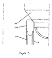
- Figure 3 is a partial cross-section of the reactor vertical arrangement in Figure 1 as seen from B.
- Figure 4 is a partial cross-section of the reactor vertical arrangement in Figure 1 as seen from C.
- Figure 5 is a partial cross-section of the reactor vertical arrangement in Figure 1 as seen from D-D.
- Figure 6 is a partial cross-section of the reactor vertical arrangement in Figure 1 as seen from E-E.
- Figure 7 is a partial cross-section of the reactor vertical arrangement in Figure 6 as seen from F.
- Figure 8 is a partial cross-section of the reactor vertical arrangement in Figure 6 as seen from G showing a snubber and a fuel platelet assembly.
- Figure 9 is a side view of the snubber and fuel plate assembly shown in Figure 8.
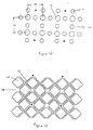
- Figure 10 shows a support plate having a conventional N lattice array configuration with approximately a 12.2 x 12.2 inch square pitch.
- Figure 11 shows a core having a conventional N lattice array configuration with approximately a 12.2 x 12.2 inch square pitch.
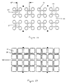
- Figure 12 shows a modification of a support plate having a K lattice array configuration with approximately a 1.414(12.2 x 12.2) inch square pitch.
- Figure 13 shows a modification of a core having a K lattice array configuration with approximately a 1.414(12.2 ⁇ 12.2) inch square pitch.
- Figure 14 shows an adaptation of a support plate for an H lattice array configuration with approximately a 1.414(12.2 x 12.2) inch square pitch.
- Figure 15 shows an adaptation of a core for an H lattice array configuration with approximately a 1.414(12.2 x 12.2) inch square pitch.
- FIG. 1 shows a cross-section of a reactor vertical arrangement 100.
- Reactor vertical arrangement 100 includes an apparatus 102 for supporting fuel assemblies 104 in a substantially cylindrical reactor pressure vessel (RPV) 106.
- Apparatus 102 includes a support plate 108 and a plurality of control rod drive (CRD) housings 110.
- Support plate 108 is mounted over CRD housings 110 and CRD housings 110 are configured to be located in RPV 106.
- CRD housings 110 are secured to, and provide support for. support plate 108 which is configured to extend across at least a portion of RPV 106.
- the manner in which CRD housings 110 engage support plate 108 provides freedom for relative expansion which may occur during reactor operating transients.
- Apparatus 102 also includes a plurality of flow tubes 112 in communication with fuel assemblies 104 and a plurality of control rod guide tubes 114.
- Flow tubes 112 and control rod guide tubes 114 are usually two separate tubes.
- a single tube 116 functions as both control rod guide tube 114 and flow tube 112.
- An inner diameter of tube 116 is sized permit tube 116 to function as flow tube 112 and an outer diameter is sized to permit tube 116 to function as control rod guide tube 114. This sizing eliminates the need for two separate tubes and allows tube 116 to serve both functions.
- Figure 2 shows support plate 108 connected to CRD housing 110 via an upper support sleeve 118, a lower support sleeve 120, and a control rod support tube 122.
- Upper and lower support sleeves 118, 120 respectively, restrain support plate 108 and are connected to control rod support tube 122 which is connected to control rod drive housing 110.
- a fine motion control rod drive 124 is positioned between control rod support tube 122 and control rod drive housing 110.
- Support plate 108 supports the weight of fuel assemblies 104 and control rod guide tubes 114 by transferring the weight of each fuel assembly 104 carried on a control rod guide tube 114 to CRD housings 110.
- Support plate 108 also serves as part of a flow partition forming an inlet plenum containing flow from recirculating pumps and directing the flow up through flow tubes 112 and thence to fuel assemblies 104.
- FIG 3 shows one of a plurality of fuel support platelets 126 positioned over guide tubes 114.
- Fuel support platelets 126 are engaged by flow tubes 112, typically in a set of four each, although the number of flow tubes 112 may vary as in the periphery of the core or with different core lattices.
- Fuel assemblies 104 sit on support platelets 126 in a conventional manner.
- An orifice (not shown) usually provided to create a single phase pressure drop in each fuel assembly inlet flow may be built into fuel support platelets 126.
- flow tubes 112 may be sized to provide the single phase pressure drop and also induce added inertia to the flow, which is desirable in controlling core stability or reducing core pressure drop.
- Figure 4 shows a seal 128 between a pump deck 130 and support plate 108.
- Seal 128 permits differential expansion between support plate 108 and pump deck 130.
- Support plate 108 is manufactured from Inconel 600 to minimize differential expansion between support plate 108 and CRD housings 110 mounted in an RPV bottom head 132.
- Seal 128, pump deck 130, and bottom head 132 form the remainder of the flow partition inlet plenum.
- Figure 5 shows a plurality of control rods 134, including small control rods 136 and large control rods 138.
- Control rods 134 are in communication with CRD housings 110. Each control rod 134 is guided between a set of control rod guide tubes 114 as contrasted with the conventional guidance within a single guide tube. In either case, control rod 134 is sheltered from recirculation water flow which is on an opposite side of guide tube 114. Rollers 140 positioned on a lower portion of control rods 134 are configured to run between opposing guide tubes 114 just as rollers (not shown) on an upper portion of control rod 134 run conventionally between opposing fuel channels (not shown).
- FIGS. 6 and 7 show an array 142 of fuel support platelets 126 horizontally restrained in a grid 144 (i.e. a platelet restraint frame).
- Grid 144 completely surrounds array 142 and is connected to a wall of RPV 106.
- Fuel support platelets 126 contain openings 146 for movement of smaller control rods through grid 144.
- a space 148 between fuel support platelets 126 allows movement of larger control rods 138 through grid 144.
- FIGS 8 and 9 show a spring loaded, adjustable snubber 150 within a snubber restraint 152.
- Belleville springs 154 are positioned between snubber 150 and snubber restraint 152 and impart to snubber 142 a spring loaded quality.
- Adjustable snubbers 150 may be provided at each end of each row of fuel support platelets 126 for positioning each row, for eliminating clearances provided during initial assembly, and for allowing flexibility for differential expansion.
- a bolt 156 in communication with snubber 150 through wedge 157 is used to adjust the position of a row of fuel support platelets 126 relative to a support frame 158.
- Grid 144 provides the required lateral restraint for fuel support platelets 126 and in turn the bottom of the core.
- the upper end of fuel assemblies 104 may be laterally restrained in a conventional grid (not shown), perhaps with small sections made removable to permit control rod 134 removal and replacement, depending on the lattice array and the size of control rods 134.
- upper tie plates (not shown) of fuel assemblies 104 may be made and laterally restrained similarly to grid 144 supporting fuel support platelets 126.
- Figures 10 and 11 show a "conventional" N lattice support plate configuration 160 and core array 162.
- a reactor can be built with RPV bottom head 132 containing N lattice configuration 160 of CRD housings 110 as established by a conventional configuration with approximately a 12.2 x 12.2 inch square pitch 164.
- N lattice configuration 160 may also be changed, by removal and replacement of reactor internal components, all of which facilitate replacement. Most internal components are small to facilitate disposal.
- support plate 108, grid 144, fuel support platelets 126, guide tubes 114, and flow tubes 112 are replaced.
- Figures 12 and 13 show a K lattice support plate configuration 166 and core array 168.
- a change from conventional N lattice configuration 160 having approximately a 12.2 x 12.2 inch square pitch 164 to K lattice configuration 166 with approximately a 1.414(12.2 x 12.2) inch square pitch 170 is accommodated by rotating the orientation of control rods 134 by approximately 45 degrees, and perhaps increasing their width.
- K lattice support plate configuration 166 and core array 168 the number of fuel assemblies 104 in RPV 106 is reduced by approximately 50 percent and the number of control rods 134 and CRD housings 110 may be reduced somewhat.
- Figures 14 and 15 show an H lattice support plate configuration 170 and core array 172.
- a change from conventional N lattice configuration 160 to H lattice configuration 170 having approximately a 1.414(12.2. x 12.2) inch square pitch 174 is similarly accommodated by eliminating approximately every other, about half, of control rods 134 and CRD housings 110 and replacing them with approximately half as many control rods 134 of approximately twice the width thereby reducing the total number of control rods 134 and CRD housings 110 by approximately 25 percent.
- a change from conventional N lattice configuration 160 to either a K lattice configuration 166 or an N lattice configuration 160 having approximately a 2.0(12.2. x 12.2) inch square pitch can be accommodated by eliminating approximately every other, about half, of the control rods 134 and CRD housings 110.
- Apparatus 102 can be retroactively applied to convert an existing RPV 106 to accommodate future core arrays.
- Apparatus 102 provides support for fuel assemblies 104 and guide tubes 114.
- apparatus 102 can be changed to accommodate the reconfigured internal components.
- Apparatus 102 could use more conventional internal components such as the core plate (not shown), fuel support (not shown), and control rod guide tube 114. Most of these components would have to be replaced once a larger control rod pitch was desired.
Landscapes
- Physics & Mathematics (AREA)
- Engineering & Computer Science (AREA)
- Plasma & Fusion (AREA)
- General Engineering & Computer Science (AREA)
- High Energy & Nuclear Physics (AREA)
- Monitoring And Testing Of Nuclear Reactors (AREA)
Priority Applications (1)
| Application Number | Priority Date | Filing Date | Title |
|---|---|---|---|
| EP00300522A EP1120793A1 (fr) | 2000-01-25 | 2000-01-25 | Structure de support pour un réseau modifiable de combustible d'un réacteur nucléaire à eau bouillante |
Applications Claiming Priority (1)
| Application Number | Priority Date | Filing Date | Title |
|---|---|---|---|
| EP00300522A EP1120793A1 (fr) | 2000-01-25 | 2000-01-25 | Structure de support pour un réseau modifiable de combustible d'un réacteur nucléaire à eau bouillante |
Publications (1)
| Publication Number | Publication Date |
|---|---|
| EP1120793A1 true EP1120793A1 (fr) | 2001-08-01 |
Family
ID=8172663
Family Applications (1)
| Application Number | Title | Priority Date | Filing Date |
|---|---|---|---|
| EP00300522A Withdrawn EP1120793A1 (fr) | 2000-01-25 | 2000-01-25 | Structure de support pour un réseau modifiable de combustible d'un réacteur nucléaire à eau bouillante |
Country Status (1)
| Country | Link |
|---|---|
| EP (1) | EP1120793A1 (fr) |
Citations (7)
| Publication number | Priority date | Publication date | Assignee | Title |
|---|---|---|---|---|
| US3650895A (en) * | 1967-04-25 | 1972-03-21 | Asea Ab | Guide tube for a control rod in a nuclear reactor |
| US4048010A (en) * | 1975-02-11 | 1977-09-13 | Kraftwerk Union Aktiengesellschaft | Control rod drive for nuclear reactors |
| US4904443A (en) * | 1988-06-02 | 1990-02-27 | General Electric Company | Control rod drive with upward removable drive internals |
| JPH06308270A (ja) * | 1993-04-28 | 1994-11-04 | Hitachi Ltd | 原子炉炉心下部構造及び制御棒案内機構並びに沸騰水型原子炉 |
| US5386440A (en) * | 1992-01-10 | 1995-01-31 | Hitachi, Ltd. | Boiling water reactor |
| US5513233A (en) * | 1993-07-08 | 1996-04-30 | Hitachi, Ltd. | Nuclear reactor |
| US5838751A (en) * | 1996-06-18 | 1998-11-17 | General Electric Company | Core plate repair using guide tube gap wedges |
-
2000
- 2000-01-25 EP EP00300522A patent/EP1120793A1/fr not_active Withdrawn
Patent Citations (7)
| Publication number | Priority date | Publication date | Assignee | Title |
|---|---|---|---|---|
| US3650895A (en) * | 1967-04-25 | 1972-03-21 | Asea Ab | Guide tube for a control rod in a nuclear reactor |
| US4048010A (en) * | 1975-02-11 | 1977-09-13 | Kraftwerk Union Aktiengesellschaft | Control rod drive for nuclear reactors |
| US4904443A (en) * | 1988-06-02 | 1990-02-27 | General Electric Company | Control rod drive with upward removable drive internals |
| US5386440A (en) * | 1992-01-10 | 1995-01-31 | Hitachi, Ltd. | Boiling water reactor |
| JPH06308270A (ja) * | 1993-04-28 | 1994-11-04 | Hitachi Ltd | 原子炉炉心下部構造及び制御棒案内機構並びに沸騰水型原子炉 |
| US5513233A (en) * | 1993-07-08 | 1996-04-30 | Hitachi, Ltd. | Nuclear reactor |
| US5838751A (en) * | 1996-06-18 | 1998-11-17 | General Electric Company | Core plate repair using guide tube gap wedges |
Non-Patent Citations (1)
| Title |
|---|
| PATENT ABSTRACTS OF JAPAN vol. 1995, no. 02 31 March 1995 (1995-03-31) * |
Similar Documents
| Publication | Publication Date | Title |
|---|---|---|
| EP0054237B1 (fr) | Barre de déplacement pour usage dans un réacteur nucléaire à dérive spectrale mécanique | |
| EP0311037B1 (fr) | Embout inférieur résistant aux débris pour assemblage de combustible nucléaire | |
| US7085340B2 (en) | Nuclear reactor fuel assemblies | |
| US6934350B1 (en) | Core configuration for a nuclear reactor | |
| US4683117A (en) | Nuclear fuel assembly incorporating primary and secondary structural support members | |
| EP0906628B1 (fr) | Assemblage combustible nucleaire | |
| US3551289A (en) | Nuclear reactor | |
| JP2521015B2 (ja) | 沸騰水型原子炉用の核燃料バンドル | |
| EP1120793A1 (fr) | Structure de support pour un réseau modifiable de combustible d'un réacteur nucléaire à eau bouillante | |
| EP0054238B1 (fr) | Réacteur à dérive spectrale | |
| EP0054787B1 (fr) | Réacteur nucléaire commandé par dérive spectrale | |
| EP2375420A2 (fr) | Zone à exposition élevée pour grappes nucléaires de réacteur d'eau bouillante | |
| US4684504A (en) | Bow resistant structural member for fuel assemblies in non-control rod locations of a nuclear reactor core | |
| EP0266592B1 (fr) | Support flexible simplifié d'une extrémité supérieure d'un tube de guidage de barres de contrôle encastré d'un côté, d'un réacteur à eau pressurisée | |
| EP0714102A1 (fr) | Assemblage de combustible avec barres partielles et éléments d'extension | |
| EP0054234B1 (fr) | Réacteur à dérive spectrale | |
| JP2001208882A (ja) | 沸騰水型原子炉用可変燃料格子用の支持構造装置 | |
| US4683116A (en) | Nuclear reactor | |
| RO120363B1 (ro) | Element combustibil, modular, adaptabil la diferite centrale nucleare, cu canale de răcire | |
| US4710340A (en) | Mechanical spectral shift reactor | |
| JP4021519B2 (ja) | 原子炉炉心に燃料を供給する方法 | |
| CA1191626A (fr) | Reacteur a derive spectrale mecanique | |
| US4692296A (en) | Mechanical spectral shift reactor | |
| Doshi et al. | Mechanical spectral shift reactor | |
| EP1168370B1 (fr) | Configuration du coeur d'un réacteur nucléaire |
Legal Events
| Date | Code | Title | Description |
|---|---|---|---|
| PUAI | Public reference made under article 153(3) epc to a published international application that has entered the european phase |
Free format text: ORIGINAL CODE: 0009012 |
|
| AK | Designated contracting states |
Kind code of ref document: A1 Designated state(s): DE SE |
|
| AX | Request for extension of the european patent |
Free format text: AL;LT;LV;MK;RO;SI |
|
| 17P | Request for examination filed |
Effective date: 20020201 |
|
| AKX | Designation fees paid |
Free format text: DE SE |
|
| 17Q | First examination report despatched |
Effective date: 20020607 |
|
| STAA | Information on the status of an ep patent application or granted ep patent |
Free format text: STATUS: THE APPLICATION IS DEEMED TO BE WITHDRAWN |
|
| 18D | Application deemed to be withdrawn |
Effective date: 20030801 |