EP1120868B1 - Modularer elektrischer Verbinder - Google Patents
Modularer elektrischer Verbinder Download PDFInfo
- Publication number
- EP1120868B1 EP1120868B1 EP01108965A EP01108965A EP1120868B1 EP 1120868 B1 EP1120868 B1 EP 1120868B1 EP 01108965 A EP01108965 A EP 01108965A EP 01108965 A EP01108965 A EP 01108965A EP 1120868 B1 EP1120868 B1 EP 1120868B1
- Authority
- EP
- European Patent Office
- Prior art keywords
- connector
- shield
- wall
- opening
- top wall
- Prior art date
- Legal status (The legal status is an assumption and is not a legal conclusion. Google has not performed a legal analysis and makes no representation as to the accuracy of the status listed.)
- Expired - Lifetime
Links
- 239000002184 metal Substances 0.000 claims 1
- 239000011888 foil Substances 0.000 description 3
- 238000003780 insertion Methods 0.000 description 2
- 230000037431 insertion Effects 0.000 description 2
- 238000002788 crimping Methods 0.000 description 1
- 238000000034 method Methods 0.000 description 1
Images


Classifications
-
- H—ELECTRICITY
- H01—ELECTRIC ELEMENTS
- H01R—ELECTRICALLY-CONDUCTIVE CONNECTIONS; STRUCTURAL ASSOCIATIONS OF A PLURALITY OF MUTUALLY-INSULATED ELECTRICAL CONNECTING ELEMENTS; COUPLING DEVICES; CURRENT COLLECTORS
- H01R13/00—Details of coupling devices of the kinds covered by groups H01R12/70 or H01R24/00 - H01R33/00
- H01R13/648—Protective earth or shield arrangements on coupling devices, e.g. anti-static shielding
- H01R13/658—High frequency shielding arrangements, e.g. against EMI [Electro-Magnetic Interference] or EMP [Electro-Magnetic Pulse]
- H01R13/6591—Specific features or arrangements of connection of shield to conductive members
- H01R13/6592—Specific features or arrangements of connection of shield to conductive members the conductive member being a shielded cable
-
- H—ELECTRICITY
- H01—ELECTRIC ELEMENTS
- H01R—ELECTRICALLY-CONDUCTIVE CONNECTIONS; STRUCTURAL ASSOCIATIONS OF A PLURALITY OF MUTUALLY-INSULATED ELECTRICAL CONNECTING ELEMENTS; COUPLING DEVICES; CURRENT COLLECTORS
- H01R13/00—Details of coupling devices of the kinds covered by groups H01R12/70 or H01R24/00 - H01R33/00
- H01R13/648—Protective earth or shield arrangements on coupling devices, e.g. anti-static shielding
- H01R13/658—High frequency shielding arrangements, e.g. against EMI [Electro-Magnetic Interference] or EMP [Electro-Magnetic Pulse]
- H01R13/6581—Shield structure
- H01R13/6582—Shield structure with resilient means for engaging mating connector
-
- H—ELECTRICITY
- H01—ELECTRIC ELEMENTS
- H01R—ELECTRICALLY-CONDUCTIVE CONNECTIONS; STRUCTURAL ASSOCIATIONS OF A PLURALITY OF MUTUALLY-INSULATED ELECTRICAL CONNECTING ELEMENTS; COUPLING DEVICES; CURRENT COLLECTORS
- H01R13/00—Details of coupling devices of the kinds covered by groups H01R12/70 or H01R24/00 - H01R33/00
- H01R13/73—Means for mounting coupling parts to apparatus or structures, e.g. to a wall
- H01R13/74—Means for mounting coupling parts in openings of a panel
-
- H—ELECTRICITY
- H01—ELECTRIC ELEMENTS
- H01R—ELECTRICALLY-CONDUCTIVE CONNECTIONS; STRUCTURAL ASSOCIATIONS OF A PLURALITY OF MUTUALLY-INSULATED ELECTRICAL CONNECTING ELEMENTS; COUPLING DEVICES; CURRENT COLLECTORS
- H01R24/00—Two-part coupling devices, or either of their cooperating parts, characterised by their overall structure
- H01R24/60—Contacts spaced along planar side wall transverse to longitudinal axis of engagement
- H01R24/62—Sliding engagements with one side only, e.g. modular jack coupling devices
- H01R24/64—Sliding engagements with one side only, e.g. modular jack coupling devices for high frequency, e.g. RJ 45
Definitions
- the present invention relates to a modular electrical connector as defined in claim 1 of the parent application 97 104 294.0-2308.
- This shield assembly solves the problem to provide a modular electrical connector which is simple to securely assemble in the field.
- Connectors of this type are often to be stacked and mounted to a face plate by means of latching arms.
- Document EP-A-0 524 426 on which the preamble of claim 1 is based, discloses a connector having a shield 6 with a cantilever beam 82 to be secured to a housing 4. This problem is solved by a modular connector as defined in claim 1.
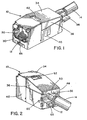
- Fig. 1 is a front perspective view of a terminated shielded modular connector of the parent application
- Fig. 2 is a rear perspective view of the terminated shielded modular connector of Fig. 1;
- Fig. 3 is an exploded view of the shielded modular connector of Fig. 1;
- Fig. 4 is a partially assembled view of the shielded modular connector of Fig. 1;
- Fig. 5 is a rear perspective view of a partially assembled modular connector
- Fig. 6 - 9 are partial rear views of a terminated modular connector.
- Fig. 10 is a side view of the shielded modular connector according to the invention latchingly engaged to a faceplate.
- shield assembly 10 is a one-piece stamped and formed housing that substantially surrounds a modular electrical connector 12 which has terminated an electrical cable 14 to provide RFI and EMI shielding.
- shield housing 10 is integrally formed to have a front wall 30 with an opening configured to surround a plug receiving opening 18 of an electrical connector 12, a base wall 38 and a pair of opposing side walls 40 positioned on the lateral edges of base 38 between the front wall 30 and the opened rear end of the shield assembly 10 and having upper extensions 42.
- the front wall 30 of the shield housing includes a pair of wiping tabs 32 which extend to the plug receiving opening 18 of the connector in order to create a continuous ground with the mated plug (not shown).
- Shield housing 10 further includes a hingedly connected top wall 34 having opposing side walls 36 and a front wall 48 that includes a grounding clip 50 having a pair of crimp tabs 52 at the end of a clip arm 54 extending from the rearward distal end of top wall 34 for engagement with a foil shield sheath 60 of the electrical cable 14 that has been terminated to the modular connector 12.
- the top wall 34 is movable from an open position to an enclosed position in which grounding clip 50 is bent down adjacent cable 14.
- Shield housing 10 also includes front and rear latch openings 66, 68 that correspond to latching areas on the modular connector 12 for latching the connector to a communication box (not shown) or other assembly.
- shield housing 10 includes top and bottom latch openings 62, 64 which provides access to the means on connector 12 for mounting to latches 74, 76 and 78 on a panel or faceplate as shown in Fig. 10.
- a standard modular electrical connector has a front end 16 that includes a plug receiving opening 18, a top 20, a pair of opposing sides 24, and a rear end 26 at which an electrical cable 14 is terminated.
- the modular connector utilized with the present invention terminates the cable 14 by a termination cap 28.
- shield assembly 10 is preformed into a box-like housing assembly that has a rear opening which in conjunction with the hingedly connected top wall 34 allows for the insertion of modular connector 12 such that the plug receiving opening 18 of connector 12 will correspond to an opening in the front shield wall 30.
- FIG. 5 shows the connector 12 inserted into the open rear end of shield housing 10 until the front end 16 of connector 12 abuts front wall 30 of shield 10.
- the rear wall sections 44, 46 are folded over the rear end 26 of the modular connector 12.
- Rear wall section 44 includes a cable support bar 58 which is disposed perpendicularly away from rear wall section 44 and situated such that the folding over of rear wall section 44 behind the inserted connector 12 positions support bar 58 adjacently underneath the terminated cable 14.
- the grounding clip 50 is then folded down adjacent the foil shield sheath 60 of the electrical cable 14 and crimped around the cable and the cable support bar 58.
- a crimp ring 56 is inserted around the grounding clip 50 and crimp tabs 52 and crimped thereto.
- the engagement of the grounding clip 50 to the electrical cable 14 closes the top wall 34 and secures the top wall 34 in an enclosed position around the connector 12.
- the support bar 58 enhances the integrity of the enclosed shield housing 10 by adding protection from the top wall 34 pulling away from the connector 12.
- shield housing 10 also includes an angled top wall portion 70 extending from the front of the top latch opening 62 downward towards the front end such that when shielded electrical connectors 12 are mounted to panels such a faceplates 72 in which multiple connectors are mounted on top of each other, angled surface 70 allows for easier insertion and removal of adjacent shielded connectors 12, as well as providing access to the latch 74, 76 by a screwdriver or other prying device (not shown).
Landscapes
- Details Of Connecting Devices For Male And Female Coupling (AREA)
- Manufacturing Of Electrical Connectors (AREA)
- Connector Housings Or Holding Contact Members (AREA)
Claims (3)
- Modularer elektrischer Steckverbinder (12) mit einer den Steckverbinder umgebenden Abschirmung, bestehend aus
einem einstückigen Metallgehäuse (10) mit einer Vorderwand (30), einem Boden (38) und zwei gegenüberliegenden Seitenwänden (40), wobei jede der Seitenwände längs einer Seitenkante des Bodens (38) zwischen der Vorderwand (30) und dem offenen hinteren Ende der Abschirmanordnung liegt, einer oberen Wand (34), und einem Rückwandabschnitt (44, 46), der in eine geschlossene Position faltbar ist, wobei die obere Wand (34) mit der Vorderwand (30) scharnierartig verbunden und aus einer offenen Position in eine geschlossene Position verstellbar ist und eine integrale Erdungsklemme (50) hat, die sich von einem hinteren distalen Ende der oberen Wand (34) aus erstreckt, und sich der hintere Wandabschnitt (44, 46) von einem hinteren Ende wenigstens einer gegenüberliegenden Seitenwand aus erstreckt,
dadurch gekennzeichnet, dass
die obere Wand (34) eine Öffnung (62) hat, um einem Arretierungsarm Zugang zum Steckverbinder (12) zu ermöglichen, und einen schrägen Abschnitt (70), der von der Abschirmöffnung (62) zum vorderen Ende des Steckverbinders nach unten abgewinkelt ist. - Abschirmanordnung nach Anspruch 1,
dadurch gekennzeichnet, dass
sich der schräge Abschnitt (70) von der Vorderseite der Abschirmöffnung (62) aus erstreckt. - Abschirmanordnung nach Anspruch 1 oder 2,
dadurch gekennzeichnet, dass
das Abschirmgehäuse (10) eine untere Arretierungsöffnung (64) hat.
Applications Claiming Priority (3)
| Application Number | Priority Date | Filing Date | Title |
|---|---|---|---|
| US08/627,241 US5733146A (en) | 1996-04-01 | 1996-04-01 | Shield for modular electrical connector |
| US627241 | 1996-04-01 | ||
| EP97104294A EP0800238B1 (de) | 1996-04-01 | 1997-03-13 | Abschirmung für modularer elektrischer Verbinder |
Related Parent Applications (1)
| Application Number | Title | Priority Date | Filing Date |
|---|---|---|---|
| EP97104294.0 Division | 1997-03-13 |
Publications (2)
| Publication Number | Publication Date |
|---|---|
| EP1120868A1 EP1120868A1 (de) | 2001-08-01 |
| EP1120868B1 true EP1120868B1 (de) | 2003-12-10 |
Family
ID=24513818
Family Applications (2)
| Application Number | Title | Priority Date | Filing Date |
|---|---|---|---|
| EP97104294A Expired - Lifetime EP0800238B1 (de) | 1996-04-01 | 1997-03-13 | Abschirmung für modularer elektrischer Verbinder |
| EP01108965A Expired - Lifetime EP1120868B1 (de) | 1996-04-01 | 1997-03-13 | Modularer elektrischer Verbinder |
Family Applications Before (1)
| Application Number | Title | Priority Date | Filing Date |
|---|---|---|---|
| EP97104294A Expired - Lifetime EP0800238B1 (de) | 1996-04-01 | 1997-03-13 | Abschirmung für modularer elektrischer Verbinder |
Country Status (4)
| Country | Link |
|---|---|
| US (1) | US5733146A (de) |
| EP (2) | EP0800238B1 (de) |
| JP (1) | JP3935238B2 (de) |
| DE (2) | DE69726770T2 (de) |
Cited By (1)
| Publication number | Priority date | Publication date | Assignee | Title |
|---|---|---|---|---|
| CN100585962C (zh) * | 2006-10-12 | 2010-01-27 | 哈廷电子有限公司及两合公司 | 连接器壳套的屏蔽接触装置 |
Families Citing this family (32)
| Publication number | Priority date | Publication date | Assignee | Title |
|---|---|---|---|---|
| TW299081U (en) * | 1996-09-23 | 1997-02-21 | Hon Hai Prec Ind Co Ltd | Miniature connector |
| JP3547034B2 (ja) * | 1997-07-10 | 2004-07-28 | 矢崎総業株式会社 | コネクタ嵌合方法及びそれに用いるコネクタ |
| JP3280610B2 (ja) * | 1997-09-09 | 2002-05-13 | ホシデン株式会社 | 表面実装コネクタソケット |
| JP3797585B2 (ja) * | 1998-08-11 | 2006-07-19 | 矢崎総業株式会社 | シールドコネクタ |
| US6142828A (en) * | 1998-11-24 | 2000-11-07 | The Whitaker Corporation | Shielded connector having adjustable cable exit |
| FR2793609B1 (fr) * | 1999-04-27 | 2001-07-13 | Sextant Avionique | Connecteur du type a entrees/sorties avec des cables blindes mis a la masse et procede de realisation et de montage d'un tel connecteur |
| US6186828B1 (en) * | 1999-08-30 | 2001-02-13 | Molex Incorporated | Electrical connector including coaxial cable management system |
| USD443859S1 (en) | 2000-10-27 | 2001-06-19 | 2Wire, Inc. | Network adapter |
| JP4575606B2 (ja) * | 2001-02-13 | 2010-11-04 | 神保電器株式会社 | 情報用コンセントおよび同コンセントに用いられるカバー部材 |
| JP2003068406A (ja) * | 2001-08-29 | 2003-03-07 | Smk Corp | シールドケース付きコネクタ |
| USD478563S1 (en) | 2001-11-16 | 2003-08-19 | Sp Controls, Inc. | Video amplifier and cable adaptor |
| KR100434230B1 (ko) * | 2002-03-26 | 2004-06-04 | 한국몰렉스 주식회사 | 고속통신용 케이블 커넥터 어셈블리 |
| US7029286B2 (en) * | 2003-02-07 | 2006-04-18 | Tyco Electronics Corporation | Plastic housings for jack assemblies |
| USD480688S1 (en) | 2003-02-10 | 2003-10-14 | Linkcom Manufacturing Co., Ltd. | Filter |
| US20040166722A1 (en) * | 2003-02-25 | 2004-08-26 | Kings Electronics Co., Inc. | Spring-biased connector mounting assembly |
| US7232340B2 (en) * | 2004-02-20 | 2007-06-19 | Adc Incorporated | Methods and systems for minimizing alien crosstalk between connectors |
| JP4596879B2 (ja) * | 2004-10-14 | 2010-12-15 | モレックス インコーポレイテド | コネクタ用シールドケース |
| US7217156B2 (en) * | 2005-01-19 | 2007-05-15 | Insert Enterprise Co., Ltd. | RF microwave connector for telecommunication |
| JP2007103249A (ja) * | 2005-10-06 | 2007-04-19 | Japan Aviation Electronics Industry Ltd | 電気コネクタ |
| US7294024B2 (en) | 2006-01-06 | 2007-11-13 | Adc Telecommunications, Inc. | Methods and systems for minimizing alien crosstalk between connectors |
| DE202007005264U1 (de) * | 2007-04-10 | 2008-08-14 | Weidmüller Interface GmbH & Co. KG | Schirmhülse |
| JP5008492B2 (ja) * | 2007-08-01 | 2012-08-22 | 株式会社オートネットワーク技術研究所 | シールドコネクタ |
| DE202008014168U1 (de) * | 2008-10-24 | 2010-03-11 | Weidmüller Interface GmbH & Co. KG | Steckverbindung mit einem Stecker- und einem Buchsenteil und diese aufnehmenden Adaptergehäusen |
| US7794279B1 (en) * | 2009-08-28 | 2010-09-14 | Cheng Uei Precision Industry Co., Ltd. | Plug connector |
| WO2013002370A1 (ja) * | 2011-06-30 | 2013-01-03 | 株式会社フジクラ | 編組線の端末構造および編組線の端末処理方法 |
| DE102011054563B3 (de) * | 2011-10-18 | 2013-01-24 | HARTING Electronics GmbH | Steckverbinder |
| US8758065B2 (en) * | 2011-11-16 | 2014-06-24 | Panduit Corp. | High bandwidth jack with RJ45 backwards compatibility |
| DE102011055509B4 (de) * | 2011-11-18 | 2017-09-07 | Phoenix Contact Gmbh & Co. Kg | Steckverbinder |
| WO2015164538A1 (en) | 2014-04-23 | 2015-10-29 | Tyco Electronics Corporation | Electrical connector with shield cap and shielded terminals |
| CN105206980B (zh) * | 2014-06-09 | 2018-02-02 | 富士康(昆山)电脑接插件有限公司 | 线缆连接器组件 |
| DE102019200713B3 (de) * | 2019-01-22 | 2020-07-23 | Robert Bosch Gmbh | Ethernet-Steckverbinder für ein Kraftfahrzeug und Steckverbinderanordnung mit einem Ethernet-Steckverbinder |
| EP3930112A1 (de) * | 2020-06-24 | 2021-12-29 | Rosenberger Hochfrequenztechnik GmbH & Co. KG | Elektrischer steckverbinder und verfahren zur montage eines elektrischen steckverbinders |
Family Cites Families (22)
| Publication number | Priority date | Publication date | Assignee | Title |
|---|---|---|---|---|
| US4337989A (en) * | 1980-05-28 | 1982-07-06 | Amp Incorporated | Electromagnetic shielded connector |
| US4457576A (en) * | 1982-12-17 | 1984-07-03 | Amp Incorporated | One piece metal shield for an electrical connector |
| JPS59166382U (ja) * | 1983-04-25 | 1984-11-07 | 第一電子工業株式会社 | シ−ルドコネクタ |
| US4653825A (en) * | 1985-09-06 | 1987-03-31 | Amp Incorporated | Shielded electrical connector assembly |
| US4738637A (en) * | 1985-10-11 | 1988-04-19 | Amp Incorporated | Receptacle assembly with ground plane spring |
| US4732568A (en) * | 1986-03-17 | 1988-03-22 | Virginia Plastics Company | Electrical connector with integral ground strap for shielded cable |
| JPH0630263B2 (ja) * | 1989-11-17 | 1994-04-20 | ヒロセ電機株式会社 | 多芯ケーブル用コネクタ |
| JPH0452370U (de) * | 1990-09-10 | 1992-05-01 | ||
| US5083945A (en) * | 1991-02-01 | 1992-01-28 | Molex Incorporated | Shielded electrical connector assembly |
| US5236375A (en) * | 1991-05-09 | 1993-08-17 | Molex Incorporated | Electrical connector assemblies |
| US5207597A (en) * | 1991-06-21 | 1993-05-04 | Amp Incorporated | Shielded connector with dual cantilever panel grounding beam |
| US5137472A (en) * | 1991-11-01 | 1992-08-11 | Amp Incorporated | Means for securing ground plates to electrical connector housing |
| EP0552683A1 (de) * | 1992-01-24 | 1993-07-28 | The Whitaker Corporation | In der gleichen Ebene durch Zug lösbares Verriegelungsglied für elektrische Verbinder |
| US5228872A (en) * | 1992-05-05 | 1993-07-20 | Dan-Chief Enterprise Co., Ltd. | Shielded IDC type modular jack adapter |
| US5199891A (en) * | 1992-05-13 | 1993-04-06 | Amp Incorporated | Cable strain relief for shielded electrical connector |
| US5254010A (en) * | 1992-09-16 | 1993-10-19 | Amp Incorporated | Securing a surface mount electrical connector in a metal shielding shell |
| US5267868A (en) * | 1992-10-01 | 1993-12-07 | Molex Incorporated | Shielded electrical connector assemblies |
| DE9214719U1 (de) * | 1992-10-29 | 1992-12-17 | Siemens AG, 8000 München | Geschirmter Stecker mit Kabelanschluß |
| TW218938B (en) * | 1993-04-12 | 1994-01-11 | Whitaker Corp | Electrical connector assembly |
| US5378172A (en) * | 1994-03-10 | 1995-01-03 | Molex Incorporated | Low profile shielded jack |
| TW286443B (de) * | 1994-10-25 | 1996-09-21 | Fridolin Alois Frech | |
| US5496195A (en) * | 1995-03-13 | 1996-03-05 | The Whitaker Corporation | High performance shielded connector |
-
1996
- 1996-04-01 US US08/627,241 patent/US5733146A/en not_active Expired - Lifetime
-
1997
- 1997-03-13 DE DE69726770T patent/DE69726770T2/de not_active Expired - Fee Related
- 1997-03-13 DE DE69707543T patent/DE69707543T2/de not_active Expired - Fee Related
- 1997-03-13 EP EP97104294A patent/EP0800238B1/de not_active Expired - Lifetime
- 1997-03-13 EP EP01108965A patent/EP1120868B1/de not_active Expired - Lifetime
- 1997-03-25 JP JP07186797A patent/JP3935238B2/ja not_active Expired - Fee Related
Cited By (1)
| Publication number | Priority date | Publication date | Assignee | Title |
|---|---|---|---|---|
| CN100585962C (zh) * | 2006-10-12 | 2010-01-27 | 哈廷电子有限公司及两合公司 | 连接器壳套的屏蔽接触装置 |
Also Published As
| Publication number | Publication date |
|---|---|
| JP3935238B2 (ja) | 2007-06-20 |
| US5733146A (en) | 1998-03-31 |
| EP1120868A1 (de) | 2001-08-01 |
| DE69707543T2 (de) | 2002-06-20 |
| DE69726770T2 (de) | 2004-09-23 |
| EP0800238A3 (de) | 1998-11-11 |
| JPH1032054A (ja) | 1998-02-03 |
| DE69707543D1 (de) | 2001-11-29 |
| EP0800238A2 (de) | 1997-10-08 |
| DE69726770D1 (de) | 2004-01-22 |
| EP0800238B1 (de) | 2001-10-24 |
Similar Documents
| Publication | Publication Date | Title |
|---|---|---|
| EP1120868B1 (de) | Modularer elektrischer Verbinder | |
| US6142828A (en) | Shielded connector having adjustable cable exit | |
| EP0671785B1 (de) | Abgeschirmte Steckbuchse mit niedrigem Profil | |
| US5941733A (en) | Universal serial bus plug connector | |
| US5775946A (en) | Shielded multi-port connector and method of assembly | |
| EP0822623B1 (de) | Abschirmung für einen modularen Jack-Verbinder | |
| EP0981180B1 (de) | Abgeschirmter Verbinder | |
| US6231392B1 (en) | Cable interconnection | |
| US6017245A (en) | Stamped backshell assembly with integral front shield and rear cable clamp | |
| US4457575A (en) | Electrical connector having improved shielding and keying systems | |
| JP4070166B2 (ja) | Lan用電気コネクタ | |
| EP0649190B1 (de) | Abgeschirmter elektrischer Verbinder | |
| EP0224200A2 (de) | Abgeschirmte Steckerbuchse-Steckverbindung | |
| EP0917745B1 (de) | Abgeschirmtes, hohe dichtung verbindungspanel | |
| CN1223746A (zh) | 屏蔽电联接器 | |
| US5667407A (en) | Shielded cable plug | |
| EP0584937B1 (de) | Abschirmung eines oberflächenmontierten elektrischen Verbinders | |
| US5975955A (en) | Shielded electrical connector assembly with grounding system | |
| EP0587303A2 (de) | Abgeschirmter Verbinder zur Datenübertragung |
Legal Events
| Date | Code | Title | Description |
|---|---|---|---|
| PUAI | Public reference made under article 153(3) epc to a published international application that has entered the european phase |
Free format text: ORIGINAL CODE: 0009012 |
|
| AC | Divisional application: reference to earlier application |
Ref document number: 800238 Country of ref document: EP |
|
| AK | Designated contracting states |
Kind code of ref document: A1 Designated state(s): DE FR GB |
|
| 17P | Request for examination filed |
Effective date: 20011119 |
|
| AKX | Designation fees paid |
Free format text: DE FR GB |
|
| GRAH | Despatch of communication of intention to grant a patent |
Free format text: ORIGINAL CODE: EPIDOS IGRA |
|
| GRAS | Grant fee paid |
Free format text: ORIGINAL CODE: EPIDOSNIGR3 |
|
| GRAA | (expected) grant |
Free format text: ORIGINAL CODE: 0009210 |
|
| AC | Divisional application: reference to earlier application |
Ref document number: 0800238 Country of ref document: EP Kind code of ref document: P |
|
| AK | Designated contracting states |
Kind code of ref document: B1 Designated state(s): DE FR GB |
|
| REG | Reference to a national code |
Ref country code: GB Ref legal event code: FG4D |
|
| REF | Corresponds to: |
Ref document number: 69726770 Country of ref document: DE Date of ref document: 20040122 Kind code of ref document: P |
|
| ET | Fr: translation filed | ||
| PLBE | No opposition filed within time limit |
Free format text: ORIGINAL CODE: 0009261 |
|
| STAA | Information on the status of an ep patent application or granted ep patent |
Free format text: STATUS: NO OPPOSITION FILED WITHIN TIME LIMIT |
|
| 26N | No opposition filed |
Effective date: 20040913 |
|
| PGFP | Annual fee paid to national office [announced via postgrant information from national office to epo] |
Ref country code: GB Payment date: 20080312 Year of fee payment: 12 |
|
| PGFP | Annual fee paid to national office [announced via postgrant information from national office to epo] |
Ref country code: DE Payment date: 20080306 Year of fee payment: 12 Ref country code: FR Payment date: 20080311 Year of fee payment: 12 |
|
| GBPC | Gb: european patent ceased through non-payment of renewal fee |
Effective date: 20090313 |
|
| REG | Reference to a national code |
Ref country code: FR Ref legal event code: ST Effective date: 20091130 |
|
| PG25 | Lapsed in a contracting state [announced via postgrant information from national office to epo] |
Ref country code: DE Free format text: LAPSE BECAUSE OF NON-PAYMENT OF DUE FEES Effective date: 20091001 |
|
| PG25 | Lapsed in a contracting state [announced via postgrant information from national office to epo] |
Ref country code: FR Free format text: LAPSE BECAUSE OF NON-PAYMENT OF DUE FEES Effective date: 20091123 Ref country code: GB Free format text: LAPSE BECAUSE OF NON-PAYMENT OF DUE FEES Effective date: 20090313 |