EP1120873A1 - Dispositif de support pour le montage d'au moins un appareil électrique sur un rail DIN - Google Patents
Dispositif de support pour le montage d'au moins un appareil électrique sur un rail DIN Download PDFInfo
- Publication number
- EP1120873A1 EP1120873A1 EP00127504A EP00127504A EP1120873A1 EP 1120873 A1 EP1120873 A1 EP 1120873A1 EP 00127504 A EP00127504 A EP 00127504A EP 00127504 A EP00127504 A EP 00127504A EP 1120873 A1 EP1120873 A1 EP 1120873A1
- Authority
- EP
- European Patent Office
- Prior art keywords
- switching device
- mounting
- hat rail
- busbar
- motor protection
- Prior art date
- Legal status (The legal status is an assumption and is not a legal conclusion. Google has not performed a legal analysis and makes no representation as to the accuracy of the status listed.)
- Granted
Links
Images
Classifications
-
- H—ELECTRICITY
- H02—GENERATION; CONVERSION OR DISTRIBUTION OF ELECTRIC POWER
- H02B—BOARDS, SUBSTATIONS OR SWITCHING ARRANGEMENTS FOR THE SUPPLY OR DISTRIBUTION OF ELECTRIC POWER
- H02B1/00—Frameworks, boards, panels, desks, casings; Details of substations or switching arrangements
- H02B1/015—Boards, panels, desks; Parts thereof or accessories therefor
- H02B1/04—Mounting thereon of switches or of other devices in general, the switch or device having, or being without, casing
- H02B1/052—Mounting on rails
-
- H—ELECTRICITY
- H02—GENERATION; CONVERSION OR DISTRIBUTION OF ELECTRIC POWER
- H02B—BOARDS, SUBSTATIONS OR SWITCHING ARRANGEMENTS FOR THE SUPPLY OR DISTRIBUTION OF ELECTRIC POWER
- H02B1/00—Frameworks, boards, panels, desks, casings; Details of substations or switching arrangements
- H02B1/015—Boards, panels, desks; Parts thereof or accessories therefor
- H02B1/04—Mounting thereon of switches or of other devices in general, the switch or device having, or being without, casing
- H02B1/056—Mounting on plugboards
- H02B1/0565—Mounting on plugboards by means of an adapter carrying one or more apparatuses
Definitions
- the invention relates to a mounting device for fastening at least one electrical switching device, in particular line circuit breaker, motor protection switch, Residual current circuit breaker and the like on a top-hat rail.
- Electrical switchgear installed in a distribution or in a switchgear are generally snapped onto a top-hat rail.
- the individual switching device has a recess on its fastening side a fixed and a movable nose, which face each other, the movable nose pressed by a spring towards the fixed nose becomes.
- Switching devices that are lined up next to each other can be connected with a Busbar or a busbar block connected what then brings a problem if one of the switchgear is defective or incorrectly dimensioned is and should be replaced.
- the busbar would be or Solve busbar block in the distribution, so that the switching device in the usual Way can be disassembled. But this means that the neighboring switchgear and any associated networks must be switched off.
- the recess is known, in particular in the case of line and residual current circuit breakers in the area of the movable nose so that the switching device crosswise can be moved to the top-hat rail, so that it from the busbar or comes free from the busbar block and can be removed. In this case the other switching devices no longer need to be switched off.
- the object of the invention is to provide a mounting device of the type mentioned to create, with which the disassembly of a switching device is facilitated.
- the mounting device has a snap-on type on the top-hat rail Lower part on which the switching device in a direction transverse to the course the top-hat rail is slidably mounted.
- the switchgear can be removed from the busbar due to the movable mounting be released and dismantled without switching off the neighboring switchgear.
- the switching device can be slidably mounted directly on the lower part.
- the holder can have an upper part which the switchgear can be attached and which is mounted displaceably in the lower part.
- the lower part has a cuboid shape Cup shape, on its cross to the top-hat rail and perpendicular to the mounting plane running sidewalls are provided grooves inside, in which the Upper part is slidably guided.
- the upper part comprises two sections, which are independent are displaceable from each other.
- the upper part formed by one or two circuit board sections.
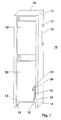
- the mounting device 10 has a cup-shaped lower housing part 11 with a rectangular bottom wall 12, on the longitudinal edges of which side walls 13 and 14 are formed are connected to a transverse edge by means of a transverse wall 15.
- Transverse wall 15 In the field of Transverse wall 15 is a recess on the outer surface of the bottom wall 12 16, which has a fixed nose 17; the movable nose, like everyone Switching device is present is not visible in Fig. 1.
- a groove 18 is provided which run parallel to the longitudinal edge of the bottom wall 12; the opposite groove in the side wall 14 is not visible.
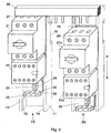
- a motor protection switch 21 is fastened on the plate 19, on which one on the plate 20 attached contactor 22 is connected.
- connecting elements 23 and 24 are provided; on the connection element 23 connect to a motor to be protected running connecting lines, whereas can connect 24 control lines to the connector.
- FIG. 2 shows two holding devices 10 and 25 arranged next to one another, as well as transversely to it a busbar arrangement 26, from which connecting lugs 27 protrude, the corresponding phase conductors within the busbar arrangement 26 are assigned so that the busbar arrangement via the connecting lugs 27 with the respective phases with the motor protection switches 21, 21a.
- the motor protection switch 21 a If, for example, the motor protection switch 21 a is now to be dismantled, then the terminals 28 are released from the terminal lugs 27, and the plates 19 and 20 can then be moved in the direction of arrow P, so that the terminals the motor protection switch 21 a free from the connecting lugs.
- a resilient arm 30 is formed, which as Latching device serves.
- a recess 31 is provided on the plate 20 a step 32 to the free end edge of the plate 20 and one towards depression 33 located at the other end edge.
- the arm 30 engages in the recess 33 a, so that the plates 19 and 20 are locked in that position in the motor protection switch 21a is free of the connection lugs. If the replaced one Motor protection switch with the busbar assembly 26 in connection is to be brought, the arm 30 is perpendicular to the longitudinal edges of the bottom wall 12 bent so that it comes out of the recess 33 and the plate 20 can be moved against the direction of arrow P. If the arm 30 behind the Step 32 snaps, see Fig. 2 in the position of the motor protection switch 21, then the plates 19, 20 are fixed.
- the plates 19 and 20 can be moved separately from one another and thus form the upper part, on which the motor protection switch 21 is fastened together with the contactor 22.
- the motor protection switch is on the plate 19 and the contactor 22 on the plate 20 attached so that, if necessary, the contactor 22 regardless of the motor protection switch 21 can be disassembled by moving the plate 20.
- the two plates 19, 20 are connected to one another in one piece.
- the contactor and the connecting part 24, which is a bus connection can remain unchanged, the plates 19, 20 are separated, and it can in the extended position (Fig. 2, right) the two switching devices 21 a, 22 a from each other be separated by moving the motor protection switch upwards in this position until it is released from the terminal lugs of the contactor 22a. After that you can the motor protection switch 21a disassembled independently of the contactor 22a and by one new motor protection switch to be replaced.
Landscapes
- Engineering & Computer Science (AREA)
- Power Engineering (AREA)
- Switch Cases, Indication, And Locking (AREA)
- Railway Tracks (AREA)
Applications Claiming Priority (2)
| Application Number | Priority Date | Filing Date | Title |
|---|---|---|---|
| DE10003349 | 2000-01-27 | ||
| DE2000103349 DE10003349B4 (de) | 2000-01-27 | 2000-01-27 | Halterungseinrichtung zur Befestigung wenigstens eines elektrischen Schaltgerätes auf einer Hutprofiltragschiene |
Publications (2)
| Publication Number | Publication Date |
|---|---|
| EP1120873A1 true EP1120873A1 (fr) | 2001-08-01 |
| EP1120873B1 EP1120873B1 (fr) | 2011-03-23 |
Family
ID=7628800
Family Applications (1)
| Application Number | Title | Priority Date | Filing Date |
|---|---|---|---|
| EP20000127504 Expired - Lifetime EP1120873B1 (fr) | 2000-01-27 | 2000-12-15 | Dispositif de support pour le montage d'au moins un appareil électrique sur un rail DIN |
Country Status (2)
| Country | Link |
|---|---|
| EP (1) | EP1120873B1 (fr) |
| DE (2) | DE10003349B4 (fr) |
Cited By (5)
| Publication number | Priority date | Publication date | Assignee | Title |
|---|---|---|---|---|
| FR2830677A1 (fr) * | 2001-10-09 | 2003-04-11 | Schneider Electric Ind Sa | Module electrique fonctionnel servant a la commande de charges telles que des moteurs |
| EP2693579A1 (fr) * | 2012-08-01 | 2014-02-05 | Hager Electro Sas | Bus d'alimentation d'appareils électriques de protection de lignes |
| US8749957B2 (en) | 2010-07-30 | 2014-06-10 | Sma Solar Technology Ag | Device for holding at least one switch in an enclosure, e.g. a switch cabinet |
| EP2874253A1 (fr) * | 2013-11-11 | 2015-05-20 | Rockwell Automation Technologies, Inc. | Système de réglage de position de disjoncteur |
| WO2021160756A1 (fr) * | 2020-02-11 | 2021-08-19 | Dehn Se + Co Kg | Agencement d'évaluation de l'état et de la qualité de réseaux à basses tensions |
Families Citing this family (6)
| Publication number | Priority date | Publication date | Assignee | Title |
|---|---|---|---|---|
| DE102004043469B4 (de) | 2004-09-08 | 2007-07-26 | Siemens Ag | Halterungseinrichtung mit einem darauf befestigten Schaltgerät |
| DE102009059014A1 (de) * | 2009-12-17 | 2011-06-22 | Phoenix Contact GmbH & Co. KG, 32825 | Vorrichtung zum Befestigen einer Moduleinheit auf einer Tragschiene |
| DE102011010828B4 (de) * | 2011-01-31 | 2016-10-13 | Block Transformatoren-Elektronik Gmbh | Klemmvorrichtung zur lösbaren Befestigung eines Gerätegehäuses an einer Profilschiene |
| DE102013103766B4 (de) | 2012-04-13 | 2019-02-21 | Gustav Hensel Gmbh & Co. Kg | System aus einem Steckmodul und einer Steckmodulführung für eine elektrische Schaltanlage |
| DE202016100307U1 (de) | 2016-01-22 | 2017-04-26 | Weidmüller Interface GmbH & Co. KG | Reihenbausteinanordnung mit einem Energiebussystem |
| DE102016125382A1 (de) | 2016-12-22 | 2018-06-28 | Phoenix Contact Gmbh & Co. Kg | Modulare Schaltschützanordnung |
Citations (2)
| Publication number | Priority date | Publication date | Assignee | Title |
|---|---|---|---|---|
| DE19738705A1 (de) * | 1997-08-29 | 1999-03-04 | Siemens Ag | Verteilungssystem der Energietechnik mit einem Geräteeinsatz |
| DE19809293C1 (de) * | 1998-03-05 | 1999-09-30 | Moeller Gmbh | Schutzeinrichtung für ein Elektroenergiesystem |
Family Cites Families (6)
| Publication number | Priority date | Publication date | Assignee | Title |
|---|---|---|---|---|
| DE3045358A1 (de) * | 1980-12-02 | 1982-07-01 | Brown, Boveri & Cie Ag, 6800 Mannheim | "adapter fuer installationsgeraete" |
| DE19515922C1 (de) * | 1995-05-02 | 1996-08-14 | Woehner Gmbh & Co Kg | Sammelschienen-Adapter mit Tragschienen |
| DE19515923C2 (de) * | 1995-05-02 | 1997-05-28 | Woehner Gmbh & Co Kg | Sammelschienen-Adapter |
| DE19715220A1 (de) * | 1997-04-11 | 1998-10-22 | Woehner Gmbh & Co Kg | Vorrichtung zur Aufnahme von Schaltgeräten oder dergleichen, insbesondere Sammelschienenadapter |
| DE19744827A1 (de) * | 1997-10-10 | 1999-04-15 | Kloeckner Moeller Gmbh | Adapter für Stromsammelschienen |
| DE19755841C1 (de) * | 1997-12-15 | 1998-12-10 | Loh Kg Rittal Werk | Adaptergehäuse für elektrische Installationsgeräte |
-
2000
- 2000-01-27 DE DE2000103349 patent/DE10003349B4/de not_active Expired - Fee Related
- 2000-12-15 DE DE50016081T patent/DE50016081D1/de not_active Expired - Lifetime
- 2000-12-15 EP EP20000127504 patent/EP1120873B1/fr not_active Expired - Lifetime
Patent Citations (2)
| Publication number | Priority date | Publication date | Assignee | Title |
|---|---|---|---|---|
| DE19738705A1 (de) * | 1997-08-29 | 1999-03-04 | Siemens Ag | Verteilungssystem der Energietechnik mit einem Geräteeinsatz |
| DE19809293C1 (de) * | 1998-03-05 | 1999-09-30 | Moeller Gmbh | Schutzeinrichtung für ein Elektroenergiesystem |
Cited By (7)
| Publication number | Priority date | Publication date | Assignee | Title |
|---|---|---|---|---|
| FR2830677A1 (fr) * | 2001-10-09 | 2003-04-11 | Schneider Electric Ind Sa | Module electrique fonctionnel servant a la commande de charges telles que des moteurs |
| US8749957B2 (en) | 2010-07-30 | 2014-06-10 | Sma Solar Technology Ag | Device for holding at least one switch in an enclosure, e.g. a switch cabinet |
| EP2693579A1 (fr) * | 2012-08-01 | 2014-02-05 | Hager Electro Sas | Bus d'alimentation d'appareils électriques de protection de lignes |
| FR2994348A1 (fr) * | 2012-08-01 | 2014-02-07 | Hager Electro Sas | Bus d'alimentation d'appareils electriques de protection de lignes |
| AU2013211495B2 (en) * | 2012-08-01 | 2014-11-06 | Hager-Electro Sas | Bus d'alimentation d'appareils electriques de protection de ligne |
| EP2874253A1 (fr) * | 2013-11-11 | 2015-05-20 | Rockwell Automation Technologies, Inc. | Système de réglage de position de disjoncteur |
| WO2021160756A1 (fr) * | 2020-02-11 | 2021-08-19 | Dehn Se + Co Kg | Agencement d'évaluation de l'état et de la qualité de réseaux à basses tensions |
Also Published As
| Publication number | Publication date |
|---|---|
| EP1120873B1 (fr) | 2011-03-23 |
| DE50016081D1 (de) | 2011-05-05 |
| DE10003349A1 (de) | 2001-08-02 |
| DE10003349B4 (de) | 2009-02-05 |
Similar Documents
| Publication | Publication Date | Title |
|---|---|---|
| EP1029389B1 (fr) | Systeme structural pour circuits de branchement de consommateurs a cablage fixe | |
| DE69017980T2 (de) | Steckdoseneinheit für ein modulares Energieverteilungssystem für Möbel. | |
| DE10137497C5 (de) | Schaltgerät | |
| EP0753916A2 (fr) | Système d'adaptateur barres conductrices | |
| DE68903836T2 (de) | Verbrauchereinheiten. | |
| EP0639877B1 (fr) | Dispositif pour alimenter en énergie électrique au moins un appareil d'installation électrique | |
| DE69201996T2 (de) | Mechanische und elektrische Zusammenfassungsvorrichtung für umspritzte Miniaturgehäuse. | |
| DE3428738A1 (de) | Installationsgeraet fuer sammelschienensysteme | |
| EP0695470B1 (fr) | Installation de distribution electrique basse tension avec un ensemble de distribution pour plusieurs supports d'appareils | |
| EP1120873B1 (fr) | Dispositif de support pour le montage d'au moins un appareil électrique sur un rail DIN | |
| BE1028102B1 (de) | Stromschienenadapter zur elektrischen Verbindung wenigstens eines Steckmoduls mit wenigstens einer Stromschiene | |
| DE102019126155A1 (de) | Stromschienenmodul und entsprechendes Anschlussmodul | |
| DE69603000T2 (de) | Elektrische Anschlussleiste | |
| DE19530659C1 (de) | Niederspannungs-Sammelschienensystem | |
| EP0821454B1 (fr) | Dispositif de raccordement pour installation électrique | |
| WO2006069634A1 (fr) | Dispositif de fixation rapide sur un appareil d'installation electrique | |
| EP1356548B1 (fr) | Dispositif de contact pour la liaison liberable d'un bloc d'assemblage mobile avec des rails conducteurs fixes | |
| DE68906737T2 (de) | Vorrichtung zur Befestigung eines modularen elektrischen Geräts auf einem Profilträger. | |
| DE10344735B4 (de) | Elektrisches Installationsgerät | |
| DE69612043T2 (de) | Schaltsystem mit Anschlussklemmenmodulen | |
| DE10146503A1 (de) | Elektrische Installationsverteilung | |
| DE69607136T2 (de) | Schalttafel und Anschlusseinrichtung für elektrische Installationen mit modularen Einrichtungen | |
| EP1353350B1 (fr) | Interrupteur auxiliaire | |
| DE19755690C2 (de) | Schaltschrank | |
| EP1251613B1 (fr) | Dispositif de connnection pour tableau électrique comportant des appareils extractibles |
Legal Events
| Date | Code | Title | Description |
|---|---|---|---|
| PUAI | Public reference made under article 153(3) epc to a published international application that has entered the european phase |
Free format text: ORIGINAL CODE: 0009012 |
|
| 17P | Request for examination filed |
Effective date: 20010602 |
|
| AK | Designated contracting states |
Kind code of ref document: A1 Designated state(s): DE FR IT |
|
| AX | Request for extension of the european patent |
Free format text: AL;LT;LV;MK;RO;SI |
|
| RAP1 | Party data changed (applicant data changed or rights of an application transferred) |
Owner name: ABB PATENT GMBH |
|
| AKX | Designation fees paid |
Free format text: DE FR IT |
|
| 17Q | First examination report despatched |
Effective date: 20060620 |
|
| GRAP | Despatch of communication of intention to grant a patent |
Free format text: ORIGINAL CODE: EPIDOSNIGR1 |
|
| RAP1 | Party data changed (applicant data changed or rights of an application transferred) |
Owner name: ABB AG |
|
| GRAS | Grant fee paid |
Free format text: ORIGINAL CODE: EPIDOSNIGR3 |
|
| GRAA | (expected) grant |
Free format text: ORIGINAL CODE: 0009210 |
|
| AK | Designated contracting states |
Kind code of ref document: B1 Designated state(s): DE FR IT |
|
| REF | Corresponds to: |
Ref document number: 50016081 Country of ref document: DE Date of ref document: 20110505 Kind code of ref document: P |
|
| REG | Reference to a national code |
Ref country code: DE Ref legal event code: R096 Ref document number: 50016081 Country of ref document: DE Effective date: 20110505 |
|
| PLBE | No opposition filed within time limit |
Free format text: ORIGINAL CODE: 0009261 |
|
| STAA | Information on the status of an ep patent application or granted ep patent |
Free format text: STATUS: NO OPPOSITION FILED WITHIN TIME LIMIT |
|
| 26N | No opposition filed |
Effective date: 20111227 |
|
| REG | Reference to a national code |
Ref country code: DE Ref legal event code: R097 Ref document number: 50016081 Country of ref document: DE Effective date: 20111227 |
|
| PG25 | Lapsed in a contracting state [announced via postgrant information from national office to epo] |
Ref country code: IT Free format text: LAPSE BECAUSE OF FAILURE TO SUBMIT A TRANSLATION OF THE DESCRIPTION OR TO PAY THE FEE WITHIN THE PRESCRIBED TIME-LIMIT Effective date: 20110323 |
|
| REG | Reference to a national code |
Ref country code: FR Ref legal event code: ST Effective date: 20120831 |
|
| REG | Reference to a national code |
Ref country code: DE Ref legal event code: R119 Ref document number: 50016081 Country of ref document: DE Effective date: 20120703 |
|
| PG25 | Lapsed in a contracting state [announced via postgrant information from national office to epo] |
Ref country code: DE Free format text: LAPSE BECAUSE OF NON-PAYMENT OF DUE FEES Effective date: 20120703 |
|
| PG25 | Lapsed in a contracting state [announced via postgrant information from national office to epo] |
Ref country code: FR Free format text: LAPSE BECAUSE OF NON-PAYMENT OF DUE FEES Effective date: 20120102 |