EP1120949A1 - Strombegrenzungsschaltung und Gerät und Fernsprechanlage mit einem solchen Gerät - Google Patents
Strombegrenzungsschaltung und Gerät und Fernsprechanlage mit einem solchen Gerät Download PDFInfo
- Publication number
- EP1120949A1 EP1120949A1 EP01420016A EP01420016A EP1120949A1 EP 1120949 A1 EP1120949 A1 EP 1120949A1 EP 01420016 A EP01420016 A EP 01420016A EP 01420016 A EP01420016 A EP 01420016A EP 1120949 A1 EP1120949 A1 EP 1120949A1
- Authority
- EP
- European Patent Office
- Prior art keywords
- current
- tongue
- circuit
- capacitor
- current limiting
- Prior art date
- Legal status (The legal status is an assumption and is not a legal conclusion. Google has not performed a legal analysis and makes no representation as to the accuracy of the status listed.)
- Withdrawn
Links
- 238000009434 installation Methods 0.000 title claims description 18
- 239000003990 capacitor Substances 0.000 claims abstract description 24
- 239000004020 conductor Substances 0.000 claims description 27
- 239000000919 ceramic Substances 0.000 claims description 3
- 238000000034 method Methods 0.000 claims description 3
- 230000000712 assembly Effects 0.000 claims 1
- 238000000429 assembly Methods 0.000 claims 1
- 230000001276 controlling effect Effects 0.000 claims 1
- 230000000149 penetrating effect Effects 0.000 claims 1
- 230000001105 regulatory effect Effects 0.000 claims 1
- RZVAJINKPMORJF-UHFFFAOYSA-N Acetaminophen Chemical compound CC(=O)NC1=CC=C(O)C=C1 RZVAJINKPMORJF-UHFFFAOYSA-N 0.000 abstract 1
- 230000002457 bidirectional effect Effects 0.000 description 6
- 230000033228 biological regulation Effects 0.000 description 3
- 230000000903 blocking effect Effects 0.000 description 2
- 239000000126 substance Substances 0.000 description 2
- 230000001052 transient effect Effects 0.000 description 2
- 238000010586 diagram Methods 0.000 description 1
- 238000003780 insertion Methods 0.000 description 1
- 230000037431 insertion Effects 0.000 description 1
- 230000010354 integration Effects 0.000 description 1
- 230000004048 modification Effects 0.000 description 1
- 238000012986 modification Methods 0.000 description 1
- 210000002445 nipple Anatomy 0.000 description 1
- 230000010287 polarization Effects 0.000 description 1
- 230000001681 protective effect Effects 0.000 description 1
Images

Classifications
-
- H—ELECTRICITY
- H04—ELECTRIC COMMUNICATION TECHNIQUE
- H04Q—SELECTING
- H04Q1/00—Details of selecting apparatus or arrangements
- H04Q1/02—Constructional details
- H04Q1/14—Distribution frames
- H04Q1/146—Distribution frames with line protection means
-
- H—ELECTRICITY
- H02—GENERATION; CONVERSION OR DISTRIBUTION OF ELECTRIC POWER
- H02H—EMERGENCY PROTECTIVE CIRCUIT ARRANGEMENTS
- H02H9/00—Emergency protective circuit arrangements for limiting excess current or voltage without disconnection
- H02H9/02—Emergency protective circuit arrangements for limiting excess current or voltage without disconnection responsive to excess current
-
- H—ELECTRICITY
- H04—ELECTRIC COMMUNICATION TECHNIQUE
- H04M—TELEPHONIC COMMUNICATION
- H04M3/00—Automatic or semi-automatic exchanges
- H04M3/18—Automatic or semi-automatic exchanges with means for reducing interference or noise; with means for reducing effects due to line faults with means for protecting lines
Definitions
- the invention relates to a current limiting circuit circulating in a pair of conductors, to a device control and / or regulation of a physical parameter of the current flowing in such a pair and at an installation telephone equipped with at least one such circuit.
- the invention aims to propose a circuit limiting current which is significantly more economical than those of the state of the art while its size is very limit.
- the invention takes advantage of the fact that, against the prejudice of a person skilled in the art, it is possible to use capacitors with a capacity of between 10 and 60 ⁇ F whose size is not too large and which must not not necessarily be chemical. These capacitors can in particular be of the SMD type (surface mountable components) and are effectively miniaturized.
- the resistor is used for current limitation while the capacitor allows the passage of an alternating signal, including low frequency, and that the bidirectional diode makes it possible to protect the assembly formed from the resistor and of the capacitor in the event of an overvoltage greater than its threshold value across the terminals of the dipole thus formed.
- the current limiting function is obtained thanks to the resistance while the bidirectional diode has a safety function making it possible to avoid damage to the resistance and / or the capacity in the event of overvoltage in the pair. conductors.
- the invention also relates to a control device and / or regulation of a physical parameter of the current circulating in a pair of conductors of an installation telephone which includes a circuit as above described.
- a control device effectively fulfills its function while it has an attractive cost price and a large compactness.
- this device comprises a tongue one end of which is capable of being inserted into a terminal of a installation connection assembly, this tab being equipped with a current limiting assembly on each of its two opposite sides.
- the device comprises advantageously two protective caps of the sets mentioned above, each cap being snap-on on the tongue in a position where it isolates a set of current by report to the outside.
- each cap is provided with a locking pin capable of entering an orifice of corresponding shape formed in the tongue.
- the cap can be provided with a generally planar extension able to be pressed against the tongue, the nipple protruding from this extension.
- the invention also relates to a telephone installation, and in particular a telephone exchange, which is equipped at least one circuit as previously described.
- a telephone installation and in particular a telephone exchange, which is equipped at least one circuit as previously described.
- Such a installation is secured against too much current important, regardless of the equipment that is connected on this installation, namely telephone terminals or telematics, such as a telephone, a fax machine, a modem, a Minitel type terminal (registered trademark), etc ...
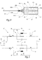
- Circuit C shown in Figure 1 is intended to be connected to conductors 1 and 2 of a pair P of conductors belonging to a telephone exchange.
- the circuit C comprises a first set E 1 of current limitation connected in series on the conductor 1 and comprising, in parallel, a resistor R 1 of value equal to approximately 200 ⁇ , a capacitor C 1 of value equal to approximately 20 ⁇ F and a bidirectional diode D 1 , the two threshold or cutoff values of which are equal to approximately 15 V.
- the diode D 1 is blocking when the voltage to which it is subjected to the terminals of the assembly E 1 which forms a dipole, is less than its two threshold values whereas it is conducting when the voltage is greater than its two values threshold.
- Diode D 1 can be of the type known under the trade name of TRANSIL diode (registered trademark.
- Diode D 1 is a fast-acting diode by clamping or "clamping". It is effective whatever the sign of the voltage at its terminals.
- a second set or dipole E 2 is mounted in series on the conductor 2 and comprises a resistor R 2 , a capacitor C 2 and a diode D 2 identical to the elements R 1 , C 1 and D 1 .
- a resistor R 3 can be considered as connected between conductors 1 and 2 and a source S 3 of potential, this resistance R 3 being representative of the internal resistance of the exchange, while a resistance R 4 is connected between the conductors 1 and 2 on the side of the site of use, this resistance being representative of the resistance of the line and, possibly, that of the device connected to this line.
- the maximum voltage U 1 to which the dipole E 1 is subjected between its junction points A 1 and B 1 to the conductor 1 is of the order of 12 V, as is the voltage corresponding U 2 between the junction points A 2 and B 2 of the assembly E 2 on the conductor 2.
- the value of the capacitor C is determined so that the dipoles E 1 and E 2 are "transparent" to the low frequency alternating currents of the baseband of the telephony. These currents have a frequency of the order of 300 Hz and it turns out in practice that a capacity of around 20 ⁇ F is satisfactory under the usual conditions of use.
- the capacitors C 1 and C 2 therefore have a value of the order of 20 ⁇ F and they can be chosen from the range sold by the company MURATA under the references GRM.
- These ceramic-based capacitors are manufactured by so-called SMD technology and have an excellent compactness while they are able to operate independently of the direction of the current I in the pair of conductors 1 and 2 because they are not polarized.
- the diodes D 1 and D 2 are dimensioned in order to protect the dipole if the voltages at the terminals of the dipoles E 1 and E 2 exceed the aforementioned maximum values U 1 and U 2 , that is to say 12 V. In practice, it is possible to choose these threshold values equal to approximately 15 V, so that the diode becomes conducting in the event of a transient overvoltage in the pair of conductors E 1 and E 2 , which can occur in the event of a thunderstorm, in particular of the lightning.
- suitable devices called para-overvoltages are capable of reacting to reduce the voltage between the conductors 1 and 2, therefore the voltages U 1 and U 2 .
- the circuit C is formed on the two opposite faces 11 and 12 of a tongue 10 of elongated shape, one end of which 13 is intended to be inserted in a terminal 21 of a connection set 20 of a telephone installation.
- screen-printed tracks 14 constituting supply lines for the dipoles E 1 and E 2 respectively formed on the faces 11 and 12 at a distance from this end.
- the tongue 10 is easy to handle and the shape of its end is compatible with the geometry of standard terminals 21 in the field of telephony.
- the dipoles E 1 and E 2 are protected by caps 31 and 32 each defining a concave volume and adapted to be clipped onto the tongue 10.
- Each cap 31 and 32 includes an edge 31a or 32a provided so as to partially overlap an edge 10 a of the tongue 10.
- Each tongue 31 and 32 also comprises an extension 31 b or 32 b generally planar and intended to come into surface support against one of the faces 11 and 12.
- In each extension 31 b and 32b is provided with a blocking pin or pin 31 c or 32 c intended to be engaged in an orifice 10 c of the tongue 10.
- caps and of the tongue are such that these caps are easily placed on the tongue by a movement of approximation represented by the arrows F 1 and F 2 in FIG. 2, this operation of latching the caps on the tongue being produced before insertion of the end 13 into the terminal 21.
Landscapes
- Engineering & Computer Science (AREA)
- Power Engineering (AREA)
- Signal Processing (AREA)
- Computer Networks & Wireless Communication (AREA)
- Devices For Supply Of Signal Current (AREA)
Applications Claiming Priority (2)
| Application Number | Priority Date | Filing Date | Title |
|---|---|---|---|
| FR0001067A FR2804550B1 (fr) | 2000-01-27 | 2000-01-27 | Circuit et dispositif limiteur du courant et installation telephonique incorporant un tel dispositif |
| FR0001067 | 2000-01-27 |
Publications (1)
| Publication Number | Publication Date |
|---|---|
| EP1120949A1 true EP1120949A1 (de) | 2001-08-01 |
Family
ID=8846386
Family Applications (1)
| Application Number | Title | Priority Date | Filing Date |
|---|---|---|---|
| EP01420016A Withdrawn EP1120949A1 (de) | 2000-01-27 | 2001-01-23 | Strombegrenzungsschaltung und Gerät und Fernsprechanlage mit einem solchen Gerät |
Country Status (2)
| Country | Link |
|---|---|
| EP (1) | EP1120949A1 (de) |
| FR (1) | FR2804550B1 (de) |
Cited By (3)
| Publication number | Priority date | Publication date | Assignee | Title |
|---|---|---|---|---|
| FR2831759A1 (fr) * | 2001-10-26 | 2003-05-02 | Mecelec Ind | Dispositif de controle et/ou de regulation de courant, installation telephonique et procede de fabrication d'un tel dispositif |
| WO2004028126A1 (de) * | 2002-09-17 | 2004-04-01 | Epcos Ag | Elektrische baugruppe und deren verwendung |
| EP3672009A1 (de) * | 2018-12-21 | 2020-06-24 | Automotive Lighting Reutlingen GmbH | Schutzschaltung, elektronische vorrichtung und verfahren zum betreiben einer elektronischen vorrichtung |
Citations (3)
| Publication number | Priority date | Publication date | Assignee | Title |
|---|---|---|---|---|
| US4203006A (en) * | 1978-04-20 | 1980-05-13 | Prentice Corporation | Direct access coupler |
| EP0625862A2 (de) * | 1993-05-19 | 1994-11-23 | Canon Kabushiki Kaisha | Steuerungsvorrichtung für Netzwerke |
| DE4402461A1 (de) * | 1994-01-28 | 1995-08-03 | Sel Alcatel Ag | Schutzschaltung für eine Teilnehmeranschlußschaltung sowie Teilnehmeranschlußschaltung damit |
-
2000
- 2000-01-27 FR FR0001067A patent/FR2804550B1/fr not_active Expired - Fee Related
-
2001
- 2001-01-23 EP EP01420016A patent/EP1120949A1/de not_active Withdrawn
Patent Citations (3)
| Publication number | Priority date | Publication date | Assignee | Title |
|---|---|---|---|---|
| US4203006A (en) * | 1978-04-20 | 1980-05-13 | Prentice Corporation | Direct access coupler |
| EP0625862A2 (de) * | 1993-05-19 | 1994-11-23 | Canon Kabushiki Kaisha | Steuerungsvorrichtung für Netzwerke |
| DE4402461A1 (de) * | 1994-01-28 | 1995-08-03 | Sel Alcatel Ag | Schutzschaltung für eine Teilnehmeranschlußschaltung sowie Teilnehmeranschlußschaltung damit |
Non-Patent Citations (1)
| Title |
|---|
| RAE D.WITHERILL: "Digital switch protection design objectives", PROCEEDINGS OF THE NATIONAL COMMUNICATIONS FORUM., vol. 40, no. 1, 1986, NATIONAL ENGINEERING CONSORTIUM INC. OAK BROOK, ILLINOIS., US, pages 129 - 135, XP002143893 * |
Cited By (3)
| Publication number | Priority date | Publication date | Assignee | Title |
|---|---|---|---|---|
| FR2831759A1 (fr) * | 2001-10-26 | 2003-05-02 | Mecelec Ind | Dispositif de controle et/ou de regulation de courant, installation telephonique et procede de fabrication d'un tel dispositif |
| WO2004028126A1 (de) * | 2002-09-17 | 2004-04-01 | Epcos Ag | Elektrische baugruppe und deren verwendung |
| EP3672009A1 (de) * | 2018-12-21 | 2020-06-24 | Automotive Lighting Reutlingen GmbH | Schutzschaltung, elektronische vorrichtung und verfahren zum betreiben einer elektronischen vorrichtung |
Also Published As
| Publication number | Publication date |
|---|---|
| FR2804550B1 (fr) | 2002-04-05 |
| FR2804550A1 (fr) | 2001-08-03 |
Similar Documents
| Publication | Publication Date | Title |
|---|---|---|
| EP0493272B1 (de) | Schutzschalter mit einer Schnittstellenkarte für einen Auslöser | |
| FR2724790A1 (fr) | Circuit de commutation | |
| FR2677831A1 (fr) | Modem a circuit d'interface de ligne perfectionne, notamment pour ordinateur. | |
| EP0415312A1 (de) | Speisungseinrichtung für ein telefonisches oder telematisches Endgerät | |
| FR2788379A1 (fr) | Port formant connecteur de transmission de donnees et d'alimentation en energie | |
| FR2600465A1 (fr) | Element de protection contre les surtensions sur les lignes telephoniques ou les lignes de transmission d'informations ou analogues | |
| EP1619924B1 (de) | Telefon-Verteilsystem | |
| FR2670340A1 (fr) | Circuit de protection a faible capacite. | |
| EP0026138B1 (de) | Elektronische Vorrichtung zum Steuern der Zündspule einer Brennkraftmaschine und Brennkraftmaschine mit einer solchen Vorrichtung | |
| EP0798910B1 (de) | Überspannungsschutz für eine Fernsprechleitungsschnittstelle | |
| FR2804550A1 (fr) | Circuit et dispositif limiteur du courant et installation telephonique incorporant un tel dispositif | |
| EP0127517B1 (de) | Verbindungssatz für Amtsleitungseinheit | |
| FR2728117A1 (fr) | Circuit de commande pour interrupteur electronique et interrupteur en faisant application | |
| EP0419363B1 (de) | Impulswahleinrichtung für ein an eine Fernsprechleitung angeschlossenes Gerät | |
| FR2538661A1 (fr) | Circuit electrique assurant les fonctions de base d'un poste telephonique d'abonne | |
| FR2535539A1 (fr) | Montage de protection pour signaux analogiques et/ou numeriques | |
| EP1632084B1 (de) | Impedanzadapter für einen übertragungskanal mit hoher bandbreite eines kupferverdrahteten terminal-systems | |
| EP1553677A1 (de) | Spannungsausgleichsregelung von elektrochemischen Sekundärgeneratoren in wiederaufladbaren Batterie durch | |
| EP0647005B1 (de) | Parallel- und Serienschutzmodul | |
| EP0909000B1 (de) | Schutzeinrichtung für eine Kondensatorbatterie | |
| FR2637752A1 (fr) | Dispositif de limitation de courant de ligne pour terminal telephonique | |
| FR2811153A1 (fr) | Limiteur de courant pour ligne telephonique | |
| FR2736154A1 (fr) | Montage de protection contre les surtensions | |
| WO1997038395A1 (fr) | Objet électronique portatif pour l'echange d'informations a distance | |
| FR2863409A1 (fr) | Module et reglette d'interconnexion de cables |
Legal Events
| Date | Code | Title | Description |
|---|---|---|---|
| PUAI | Public reference made under article 153(3) epc to a published international application that has entered the european phase |
Free format text: ORIGINAL CODE: 0009012 |
|
| AK | Designated contracting states |
Kind code of ref document: A1 Designated state(s): AT BE CH CY DE DK ES FI FR GB GR IE IT LI LU MC NL PT SE TR |
|
| AX | Request for extension of the european patent |
Free format text: AL;LT;LV;MK;RO;SI |
|
| AKX | Designation fees paid | ||
| REG | Reference to a national code |
Ref country code: DE Ref legal event code: 8566 |
|
| STAA | Information on the status of an ep patent application or granted ep patent |
Free format text: STATUS: THE APPLICATION IS DEEMED TO BE WITHDRAWN |
|
| 18D | Application deemed to be withdrawn |
Effective date: 20020202 |