EP1120977A1 - MPEG Dekoder von Bildern von mehreren Sequenzen - Google Patents
MPEG Dekoder von Bildern von mehreren Sequenzen Download PDFInfo
- Publication number
- EP1120977A1 EP1120977A1 EP01410005A EP01410005A EP1120977A1 EP 1120977 A1 EP1120977 A1 EP 1120977A1 EP 01410005 A EP01410005 A EP 01410005A EP 01410005 A EP01410005 A EP 01410005A EP 1120977 A1 EP1120977 A1 EP 1120977A1
- Authority
- EP
- European Patent Office
- Prior art keywords
- images
- decoding
- circuit
- type
- image
- Prior art date
- Legal status (The legal status is an assumption and is not a legal conclusion. Google has not performed a legal analysis and makes no representation as to the accuracy of the status listed.)
- Granted
Links
Images

Classifications
-
- H—ELECTRICITY
- H04—ELECTRIC COMMUNICATION TECHNIQUE
- H04N—PICTORIAL COMMUNICATION, e.g. TELEVISION
- H04N19/00—Methods or arrangements for coding, decoding, compressing or decompressing digital video signals
- H04N19/42—Methods or arrangements for coding, decoding, compressing or decompressing digital video signals characterised by implementation details or hardware specially adapted for video compression or decompression, e.g. dedicated software implementation
-
- H—ELECTRICITY
- H04—ELECTRIC COMMUNICATION TECHNIQUE
- H04N—PICTORIAL COMMUNICATION, e.g. TELEVISION
- H04N19/00—Methods or arrangements for coding, decoding, compressing or decompressing digital video signals
- H04N19/60—Methods or arrangements for coding, decoding, compressing or decompressing digital video signals using transform coding
- H04N19/61—Methods or arrangements for coding, decoding, compressing or decompressing digital video signals using transform coding in combination with predictive coding
Definitions
- the present invention relates to decoding circuits of images coded according to the MPEG standard, and more precisely a control circuit of an MPEG decoder capable of decoding a plurality of images in a reduced duration, for example a period vertical scan of a television screen, to view several TV channels at the same time.
- the MPEG coding standard allows images to be stored a sequence of digital images in a reduced memory space, or to transmit these images in a reduced bit rate channel.
- a encoded image must be decoded before it can be displayed, for example example on a television screen.
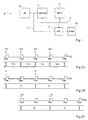
- FIG. 1 shows schematically in the form of blocks the main elements of a decoding device 2 and display of digital image sequences coded according to the MPEG standard.
- This device includes a decoder (DECOD) 4 connected via a bus 6 to a memory (MEM) 8 in which are stored the coded images to be decoded. Images decoded by the decoder are temporarily stored in memory 8, before being supplied to a screen (SCRN) 10 connected to bus 6 via a control device and display management (DIS) 12.
- SCRN screen
- DIS control device and display management
- the decoder and the controller displays are controlled by a circuit such as a microprocessor ( ⁇ P) 14 connected via a bus 7 of way to provide and receive control signals as well as Datas.
- ⁇ P microprocessor
- the microprocessor 14 gives in particular to the decoder the decoding orders of the coded images stored in the memory 8. Conventionally, to order the decoding of a coded image stored in an area of memory 8, microprocessor 14 provides the decoder 4 with the address of the start of this zone, and the command to decode the image from a given instant. The operation of such a circuit is well known to those skilled in the art trade and it will not be detailed further.
- Existing analog television systems offer conventionally to display several images on the screen during of the same screen scan. This allows for example to display one or more images embedded in a main image and to view several television channels simultaneously. he there is a need for a device for decoding coded images according to the MPEG standard allowing such simultaneous display, that is to say for decoding a plurality of images into one vertical scanning period of a television screen.
- the device of FIG. 1 makes it possible to decode and display the images of a single image sequence. So a solution is to duplicate this device as many times as one wants images decoded and displayed simultaneously.
- an image can be coded in three different ways: either in the form of a complete image including the two interlaced frames (image "frame"), either in the form of two half-images, each of which corresponds to one of the frames ("field” images), ie still under the shape of a complete non-interlaced image (image "progressive").
- image "frame" the two interlaced frames
- field images two half-images, each of which corresponds to one of the frames
- image "progressive” image "progressive”
- the rest of the description deals only with interlaced images of two types, progressive images can, in known manner, be treated in the same way as the interlaced half-images.
- the same sequence of images can be composed of images corresponding to the two types of coding.
- the different sequences of images that we want to decode and display simultaneously can also have different codings.
- the decoding of each type of coded image corresponds to an operation particular of the decoder 4.
- FIG. 2A illustrates the decoding of a sequence of two images I 1 and I 4 , each coded in the form of two half-images I 1T and I 1B , and I 4T and I 4B respectively.
- the frame contained in each decoded half-image must be displayed in a T VSYNC period, and a half-image can therefore be decoded in a T VSYNC period.
- the decoder 4 receives from the microprocessor 14 the order to decode the half-images I 1T , I 1B , I 4T , I 4B respectively at times t 100 , t 200 , t 300 and t 400 each distant by a period T VSYNC .
- the respective decodings of the half-images I 1T , I 1B , I 4T and I 4B take place in the period T VSYNC which immediately follows the order to decode them. It will be noted that, to ensure proper operation of the decoding and display device, it is desirable that the decoding of a half-image is not longer than a maximum duration equal to a period T VSYNC and does not exceed over the next period.
- FIG. 2B illustrates the decoding of a sequence of two images I 2 and I 5 coded in the form of complete images.
- the two frames included in a decoded complete image must be displayed during two consecutive T VSYNC periods, and a complete image can be decoded in two T VSYNC periods.
- the decoder 4 receives from the microprocessor 14 the order to decode the complete images I 2 and I 5 respectively at times t 100 and t 300 .
- the respective decodings of the images I 2 and I 5 take place during the two successive periods T VSYNC which immediately follow the order to decode them. In this case also, it is desirable to ensure proper operation that the decoding does not exceed the maximum duration, here of two periods, which is allocated to it.
- the memory 8 is a buffer memory which contains only a few images of a sequence, which are written and read in phase with the reception of the sequence by the decoding and display device.
- these sequences are not in phase, in terms of T VSYNC periods, and that they must be decoded and displayed with this phase shift.
- two sequences of images coded in the form of complete images can be offset by a screen scanning period T VSYNC .
- FIG. 2C illustrates the decoding of a sequence composed of two images I 3 and I 6 coded in the form of complete images, the decoding order of which is given to the decoder 4 with a phase shift of a period T VSYNC with respect to the sequence of Figure 2B.
- the order to decode the images I 3 and I 6 is given to the decoder at times t 200 and t 400 , and their respective decodings take place during the two successive periods T VSYNC which immediately follow the order to decode them.
- An object of the present invention is to provide such a device for decoding several images which includes only one single decoder circuit.
- the present invention provides in particular to provide this device with a particular control circuit to manage the decoding of images of several sequences, different type of coding and phase, using a single decoder.
- the present invention provides a circuit for control of an MPEG decoder clocked by a period signal given and capable of decoding several coded images, receiving at the start of each period, a decoding command for several images of a first or a second type, the images of the second type can be decoded at any time of the period following their decoding command, and the images of the first type can be decoded at any time two periods following their decoding command, including a priority allocation circuit for, for each period, give among these images the priority of decoding, if any, to the images of the first type which have still not been decoded a period after their decoding command and if not, if there is one, to images of the second type.
- control circuit further comprises a pointer memory intended to store the starting addresses of each image to be displayed.
- control circuit further comprises a safety circuit to add a predetermined header before each image provided to the decoder so that two images placed end to end do not cannot form a code that causes a malfunction of the decoder.
- the present invention also relates to a circuit for integrated control decoding including a connected MPEG decoder to such a control circuit.
- the present invention also relates to a circuit for decoding and display of images coded according to the MPEG standard, comprising such a decoding circuit with integrated control connected so as to read coded data and write data decoded in a memory via a first bus, a display control circuit connected between a screen and the first bus, and a microprocessor connected to a second bus so as to control the decoding circuit with integrated control and the display control circuit.
- the images of the first type are complete interlaced images
- the images of the second type are interlaced half-images.
- the images of the first type are complete interlaced images
- the images of the second type are interlaced half-images or full non-interlaced images.
- FIG. 3 shows in block form a decoding and display device 16 according to the present invention, which makes it possible to process the images of several distinct sequences, for example three, in one screen scanning period.
- the device 16 comprises a decoding circuit with integrated control (COMDEC) 18 connected so as to read the coded data of the three sequences and to write the decoded data in a memory 8 via a bus 6.
- a control circuit display 20 has its output connected to a screen 10.
- the input of circuit 20 is connected to bus 6 so as to read in memory 8 the decoded images of the three sequences and to transmit them to screen 10
- the display control circuit 20 is more complex than the circuit 12 in FIG. 1, and that it is in particular capable of accessing the data of several images in memory and of presenting them adequately to the user.
- the decoding circuit with integrated control 18 includes a decoder circuit 4 identical to the decoder of FIG. 1, and a circuit (COM) 24 of the decoder circuit. It will be noted that, for the device according to the present invention to operate, it is necessary for the decoder 4 to operate at a speed at least three times greater than the speed described in relation to FIGS. 2A to 2C, that is to say that it must be able to decode in two T VSYNC periods three complete images or six half-images, or any equivalent combination. This condition is fulfilled by most decoders according to the state of the art, and it does not in practice constitute a limitation.
- control circuit 24 has the function of determining which images must be decoded as a priority.
- the control circuit 24 also has the function of ensuring the compatibility of the data which is supplied to the decoder 4 with the MPEG syntax.
- FIG. 4 represents in block form a mode of realization of the control circuit 24 according to the present invention.
- Circuit 24 includes a pointer memory address (ADP) 26, for example composed of registers, connected to bus 7 to receive addresses (or pointers) from the start of memory areas 8 in which the images to be decoded and the decoding parameters are stored of these images.
- the decoding parameters are used in particular for identify the type of images to decode. There are as many games parameters and memory pointers as sequences to be decoded in parallel.
- Memory 26 is connected to decoder 4 for it provide the addresses (or pointers) from which the decoder must access memory 8, via bus 6, to perform its task.
- control circuit 24 includes a priority allocation circuit 30 connected to the memory 26 so as to receive the decoding parameters associated with each image to be decoded.
- the circuit 30 is also connected to decoder 4 so as to command the decoder to read in memory 8 of the images designated by the pointers of the registers 26 with an order of priority which will be described, and so as to control the decoder circuit 4 so that it decodes the images provided by memory 8. It will be noted that once the decoding parameters and the address pointer were taken in account by the control circuit, the contents of the registers of the block 26 can be renewed with a following image.
- circuits 4 and 24 are synchronized over the vertical scanning period T VSYNC , and a new decoding order can be given by the microprocessor 14 at each period.
- the circuit 30 calculates a new order of priority for decoding the images whose pointer and the identification parameters have just been written in the memory 26.
- the priority management circuit 30 assigns a decoding priority to each pointer, then it commands the decoder 4 to decode the images designated by the pointers with the highest priority.
- the highest decoding priority is given to complete images whose pointer has been present in the memory 26 for a duration greater than a period T VSYNC , that is to say complete images whose order decoding is more than one T VSYNC period.
- a lower decoding priority is given to the half-images, and the lower decoding priority is given to the complete images whose pointer has been present in the memory 26 for less than a period T VSYNC . This operation is illustrated in Figures 5 and 6.
- FIG. 5 illustrates the decoding of two half-images I 1T , I 1B whose decoding order is given at times t 100 and t 200 , and of two complete images I 2 and I 3 whose decoding order is given at time t 100 .
- the pointers and the parameters of the images I 1T , I 2 and I 3 are written in the memory 26 before the instant t 100 , and the pointer of the image I 1B before the instant t 200 .
- the priority management circuit 30 gives the highest decoding priority to the half-image I 1T , and a low decoding priority level to the images I 2 and I 3 .
- the half-image I 1T is decoded in priority, between the instant t 100 and an instant t 133 located at the third of the interval t 100 -t 200 , then one of the two images I2, I3, for example the image I 2 , is decoded between time t 133 and time t 200 .
- the memory 26 thus contains the pointers of the half-image I 1B and of the complete image I 3 .
- the image pointer I 3 has been in memory 26 for more than one period T VSYNC , and circuit 30 assigns it the highest decoding priority.
- the half-image I 1B receives the lowest priority.
- the image I 3 is decoded between the instant t 200 and an instant t 266 located at two thirds of the interval t 200 -t 300 .
- the half-image I 1B is decoded between time t 266 and time t 300 .
- the device according to the present invention also makes it possible to decode in two periods T VSYNC , two images coded in the form of half-images and a complete image, only images coded in the form of half-image, or only images coded in as complete images. Other, more complex decoding combinations can also be processed by this device.
- FIG. 6 illustrates a complex decoding combination in which the order of decoding of two half-images I 1T and I 1B is given at times t 100 and t 200 , the order of decoding of two complete pictures I 2 and I 3 is given at time t 200 , the decoding order of two half-images I 4T and I 4 B is given at times t 300 and t 400 , and the decoding order of a complete image I 5 is given at time t 300 .
- the memory 26 contains only the pointer of the half-image I 1T , which is decoded between the instant t 100 and the instant t 133 .
- the memory 26 contains the pointers of the half-image I 1B and those of the complete images I 2 and I 3 .
- the priority management circuit assigns the highest decoding priority to the half-image I 1B , which is decoded between the instants t 200 and t 233 .
- the two complete images I 2 and I 3 then have a low decoding priority, and one of them, for example the image I 2 , is decoded between the instants t 233 and t 300 .
- the memory 26 contains the pointers of the half-image I 4T and of the complete images I 3 and I 5 .
- the priority management circuit gives the highest decoding priority to the complete image I 3 .
- a lower decoding priority is given to the half-image I 4T , and the lower decoding priority is given to the complete image I 5 .
- the complete image I 3 is decoded between the instant t 300 and an instant t 366 , located at two thirds of the interval t 300 -t 400 , and the half-image I 4T is decoded between the instant t 366 and the instant t 400 .
- the memory 26 contains the pointers of the complete image I 5 and of the half-image I 4B , and the decoding priority is given to the complete image I 5 .
- the image I 5 is decoded between the instant t 400 and an instant t 466
- the half-image I 4B is decoded between the instant t 466 and the instant t 500 .
- the priority management according to the present invention makes it possible to always decode a half-image in the period T VSYNC which follows its decoding order, and to always decode a complete image in the two periods T VSYNC which follow its decoding order .
- the decoder 4 then receives the image data to be decoded from different sequences of images, read in memory 8.
- the decoder 4 is a conventional MPEG decoder.
- the decoding of an image ends when the decoder detects a code (PSC) marking the start of the next image.
- PSC code marking the start of the next image.
- This code is defined by MPEG standard.
- the decoder 4 reads in memory 8 the image it decodes until it detects the PSC code of the following image stored in memory 8.
- Such a image conventionally the following image of the sequence at which belongs to the decoded image, is different from the image to be decoded next, whose pointer is in memory 26.
- a classic MPEG decoder includes an internal buffer area in which part of the data is permanently contained of the decoded image.
- this memory area includes the latest data from the decoded image as well as spurious data corresponding to the PSC code and the first data of the following frame of the sequence. This memory area cannot be reset, so that decoder 4 receives this data noise before receiving the image data to be decoded next.
- This data begins with a PSC code which triggers the next decoding.
- the end-to-end insertion of the parasitic data and of the PSC code of the following image to be decoded is likely to take the form of a PSC code.
- the PSC codes correspond to a particular sequence of eight bytes having the values 00, 00, 00, 00, 01, 00 and 00 respectively, and the spurious data ends in six bytes having the values 00 respectively , 00, 00, 00, 00 and 01
- the end-to-end insertion of the parasitic data and the PSC code of the following image will be the sequence of bytes 00 00 00 00 00 01 00 00 00 00 01 00 00 and the decoder will identify the first eight bytes of this expression as being a PSC code.
- the present invention provides for interposing, between the end of the parasitic data and the PSC code of the image to be decoded next, a security header eliminating any risk of erroneous generation of a PSC code by placing the spurious data and the following PSC code.
- the security header can consist of a byte encoded with the value FF.
- the end-to-end insertion of the parasitic data, the security header and the PSC code is a series of bytes 00 00 00 00 00 01 FF 00 00 00 00 00 01 00 00, which presents no risk of incorrect identification of the PSC code.
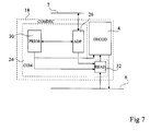
- FIG. 7 represents in the form of blocks a circuit 18 as described in FIG. 4, comprising a decoder 4 and a control circuit 24, further provided with a circuit 32 for insert a security header and access the image data to the place of the decoder 4, according to the addresses provided by the memory 26.
- Circuit 32 is connected between bus 6 and the decoder 4. It is further connected to a control output decoding provided by circuit 30, so as to insert the header before the data supplied to decoder 4 from bus 6 to start of each decoding.
- the present invention is susceptible of various variants and modifications.
- a person skilled in the art will easily adapt the present invention to a priority management circuit which grants the highest priority to the half-images, then to the complete images whose starting address is contained in the memory 26 from more than one period T VSYNC , then to the complete images whose starting address is contained in the memory 26 for less than one period T VSYNC .
- the case of a device making it possible to decode and display the images belonging to three different image sequences has been described, but a person skilled in the art will easily adapt the present invention to a device making it possible to decode and display the images of two image sequences, four or more image sequences.
- each sequence comprises images of the same type
- a person skilled in the art will easily adapt the present invention to the case in which the sequences comprise images of different type.
- the case where all the images have the same size, and can be decoded in the same duration.
- a person skilled in the art will easily adapt the present invention to a case where the images of the different sequences have different respective sizes (for example high and low resolution images), and where the decoding times of the images of each sequence have different durations.
Landscapes
- Engineering & Computer Science (AREA)
- Multimedia (AREA)
- Signal Processing (AREA)
- Compression Or Coding Systems Of Tv Signals (AREA)
Applications Claiming Priority (2)
| Application Number | Priority Date | Filing Date | Title |
|---|---|---|---|
| FR0000933 | 2000-01-25 | ||
| FR0000933A FR2804274B1 (fr) | 2000-01-25 | 2000-01-25 | Decodeur mpeg d'images de sequences multiples |
Publications (2)
| Publication Number | Publication Date |
|---|---|
| EP1120977A1 true EP1120977A1 (de) | 2001-08-01 |
| EP1120977B1 EP1120977B1 (de) | 2010-03-10 |
Family
ID=8846284
Family Applications (1)
| Application Number | Title | Priority Date | Filing Date |
|---|---|---|---|
| EP01410005A Expired - Lifetime EP1120977B1 (de) | 2000-01-25 | 2001-01-24 | MPEG Dekoder von Bildern von mehreren Sequenzen |
Country Status (4)
| Country | Link |
|---|---|
| US (1) | US7369614B2 (de) |
| EP (1) | EP1120977B1 (de) |
| DE (1) | DE60141492D1 (de) |
| FR (1) | FR2804274B1 (de) |
Cited By (1)
| Publication number | Priority date | Publication date | Assignee | Title |
|---|---|---|---|---|
| EP1191795A3 (de) * | 2000-09-22 | 2004-04-14 | Matsushita Electric Industrial Co., Ltd. | Verfahren und Vorrichtung zur Bilddekodierung |
Families Citing this family (4)
| Publication number | Priority date | Publication date | Assignee | Title |
|---|---|---|---|---|
| US20040073941A1 (en) * | 2002-09-30 | 2004-04-15 | Ludvig Edward A. | Systems and methods for dynamic conversion of web content to an interactive walled garden program |
| US7865021B2 (en) * | 2004-12-06 | 2011-01-04 | Nec Electronics Corporation | Compressed stream decoding apparatus and method |
| US10043239B2 (en) | 2016-05-05 | 2018-08-07 | The Climate Corporation | Using digital images of a first type and a feature set dictionary to generate digital images of a second type |
| TWI681362B (zh) * | 2018-03-01 | 2020-01-01 | 瑞昱半導體股份有限公司 | 有限記憶體頻寬系統及其動態限制圖形處理器的記憶體頻寬的方法 |
Citations (3)
| Publication number | Priority date | Publication date | Assignee | Title |
|---|---|---|---|---|
| EP0881835A2 (de) * | 1997-05-30 | 1998-12-02 | Victor Company Of Japan, Limited | Kodier- und Dekodierverfahren für Videosignal mit Zwischenbild mit Konvertierung von periodisch ausgewählten Videohalbbildern nach Videobildern mit progressiver Abtastung |
| EP0893917A2 (de) * | 1992-09-18 | 1999-01-27 | Sony Corporation | Kodierung und Dekodierung von digitalen Bildsignalen mit aus unterschiedlichen Filmquellenbildern erzeugten doppelten Vollbildern mit Halbbildern |
| US5880786A (en) * | 1994-06-15 | 1999-03-09 | Hitachi, Ltd. | Apparatus for picture decoding having frame memories commonly connected to one data bus and one address bus |
Family Cites Families (3)
| Publication number | Priority date | Publication date | Assignee | Title |
|---|---|---|---|---|
| US5455629A (en) * | 1991-02-27 | 1995-10-03 | Rca Thomson Licensing Corporation | Apparatus for concealing errors in a digital video processing system |
| US5532751A (en) * | 1995-07-31 | 1996-07-02 | Lui; Sam | Edge-based interlaced to progressive video conversion system |
| TW376629B (en) * | 1997-12-19 | 1999-12-11 | Toshiba Corp | Digital image decoding method and device |
-
2000
- 2000-01-25 FR FR0000933A patent/FR2804274B1/fr not_active Expired - Fee Related
-
2001
- 2001-01-24 US US09/770,112 patent/US7369614B2/en not_active Expired - Lifetime
- 2001-01-24 EP EP01410005A patent/EP1120977B1/de not_active Expired - Lifetime
- 2001-01-24 DE DE60141492T patent/DE60141492D1/de not_active Expired - Lifetime
Patent Citations (3)
| Publication number | Priority date | Publication date | Assignee | Title |
|---|---|---|---|---|
| EP0893917A2 (de) * | 1992-09-18 | 1999-01-27 | Sony Corporation | Kodierung und Dekodierung von digitalen Bildsignalen mit aus unterschiedlichen Filmquellenbildern erzeugten doppelten Vollbildern mit Halbbildern |
| US5880786A (en) * | 1994-06-15 | 1999-03-09 | Hitachi, Ltd. | Apparatus for picture decoding having frame memories commonly connected to one data bus and one address bus |
| EP0881835A2 (de) * | 1997-05-30 | 1998-12-02 | Victor Company Of Japan, Limited | Kodier- und Dekodierverfahren für Videosignal mit Zwischenbild mit Konvertierung von periodisch ausgewählten Videohalbbildern nach Videobildern mit progressiver Abtastung |
Cited By (2)
| Publication number | Priority date | Publication date | Assignee | Title |
|---|---|---|---|---|
| EP1191795A3 (de) * | 2000-09-22 | 2004-04-14 | Matsushita Electric Industrial Co., Ltd. | Verfahren und Vorrichtung zur Bilddekodierung |
| US7020339B2 (en) | 2000-09-22 | 2006-03-28 | Matsushita Electric Industrial Co., Ltd. | Image decoding apparatus and image decoding method for decoding image data including plural image sequences, and program storage medium |
Also Published As
| Publication number | Publication date |
|---|---|
| US20010026592A1 (en) | 2001-10-04 |
| EP1120977B1 (de) | 2010-03-10 |
| DE60141492D1 (de) | 2010-04-22 |
| FR2804274A1 (fr) | 2001-07-27 |
| US7369614B2 (en) | 2008-05-06 |
| FR2804274B1 (fr) | 2002-04-12 |
Similar Documents
| Publication | Publication Date | Title |
|---|---|---|
| EP0821493B1 (de) | Fehlerkorrekturssystem in Datenrastern mit horizontalen und vertikalen Paritätskoden | |
| FR2555849A1 (fr) | Decodeur du type teletexte utilisant une memoire commune | |
| FR2555844A1 (fr) | Decodeur de teletexte operant sur des mots d'elements d'image | |
| CA2533169A1 (en) | Seamless transition between video play-back modes | |
| WO1991007849A1 (fr) | Procede d'embrouillage et de desembrouillage de signaux video composites, et dispositif de mise en ×uvre | |
| JP3188135B2 (ja) | 映像信号処理回路 | |
| EP4222957A1 (de) | Verfahren und elektronische vorrichtung zur decodierung eines datenstroms und zugehöriges computerprogramm und datenströme | |
| EP1120977B1 (de) | MPEG Dekoder von Bildern von mehreren Sequenzen | |
| EP0793391B1 (de) | Speicherbereichadressierung in einem MPEG-Dekodierer | |
| FR2771540A1 (fr) | Procede de codage de caracteres et d'attributs d'affichage associes dans un systeme video et dispositif mettant en oeuvre ce procede | |
| FR2740636A1 (fr) | Procede permettant la mise en cascade de modules d'acces conditionnel detachables, circuit d'insertion d'une sequence predefinie et circuit de detection de ladite sequence pour la mise en oeuvre du procede | |
| EP0967576A1 (de) | Speicheradressierung in einem MPEG-Dekodierer | |
| EP0716395B1 (de) | Verfahren zum Dekodieren komprimierter Bilder | |
| EP1147663A1 (de) | Verfahren zur gleichzeitigen aufnahme und wiedergabe eines digitalen ton- und bild-datenstromes und empfänger zur verwirklichung des verfahrens | |
| EP0841654A2 (de) | Einrichtung und Verfahren zur Steuerung der Speicherung von anzuzeigenden dekodierten Bilddaten in einem Bildspeicher | |
| EP1142324B1 (de) | Verfahren zum speichern eines digitalen audio- und videodatenflusses, speicherungsvorrichtung und empfänger zur durchführung des verfahrens | |
| US20020113828A1 (en) | Image reproducing apparatus | |
| EP1085764B1 (de) | MPEG Videodekodierung und Anzeige mit Wiederholung | |
| US20060269227A1 (en) | Subpicture display device utilizing micro-processor created subpicture address table and related method | |
| EP0716546B1 (de) | Verfahren zur Adressierung von Benutzern in einem Fernsehsystem mit reserviertem Zugriff | |
| EP0020980A2 (de) | Vorrichtung zur Anzeige durch Segmente | |
| US20060092322A1 (en) | Audio signal delay apparatus and method | |
| EP0089731B1 (de) | Verfahren zum Übersenden von Daten in einem Fernsehempfänger und Empfänger, der das Verfahren verwendet | |
| US20030049022A1 (en) | Optical disk reproducing system to reproduce still pictures and method of reproducing same | |
| EP0951180A1 (de) | Verfahren zur Erfassung von Daten in einem Videosignal |
Legal Events
| Date | Code | Title | Description |
|---|---|---|---|
| PUAI | Public reference made under article 153(3) epc to a published international application that has entered the european phase |
Free format text: ORIGINAL CODE: 0009012 |
|
| AK | Designated contracting states |
Kind code of ref document: A1 Designated state(s): DE FR GB IT |
|
| AX | Request for extension of the european patent |
Free format text: AL;LT;LV;MK;RO;SI |
|
| RAP1 | Party data changed (applicant data changed or rights of an application transferred) |
Owner name: STMICROELECTRONICS S.A. |
|
| 17P | Request for examination filed |
Effective date: 20020121 |
|
| AKX | Designation fees paid |
Free format text: DE FR GB IT |
|
| GRAP | Despatch of communication of intention to grant a patent |
Free format text: ORIGINAL CODE: EPIDOSNIGR1 |
|
| GRAS | Grant fee paid |
Free format text: ORIGINAL CODE: EPIDOSNIGR3 |
|
| GRAA | (expected) grant |
Free format text: ORIGINAL CODE: 0009210 |
|
| AK | Designated contracting states |
Kind code of ref document: B1 Designated state(s): DE FR GB IT |
|
| REG | Reference to a national code |
Ref country code: GB Ref legal event code: FG4D Free format text: NOT ENGLISH |
|
| REF | Corresponds to: |
Ref document number: 60141492 Country of ref document: DE Date of ref document: 20100422 Kind code of ref document: P |
|
| PLBE | No opposition filed within time limit |
Free format text: ORIGINAL CODE: 0009261 |
|
| STAA | Information on the status of an ep patent application or granted ep patent |
Free format text: STATUS: NO OPPOSITION FILED WITHIN TIME LIMIT |
|
| 26N | No opposition filed |
Effective date: 20101213 |
|
| PG25 | Lapsed in a contracting state [announced via postgrant information from national office to epo] |
Ref country code: IT Free format text: LAPSE BECAUSE OF FAILURE TO SUBMIT A TRANSLATION OF THE DESCRIPTION OR TO PAY THE FEE WITHIN THE PRESCRIBED TIME-LIMIT Effective date: 20100310 |
|
| PGFP | Annual fee paid to national office [announced via postgrant information from national office to epo] |
Ref country code: GB Payment date: 20101230 Year of fee payment: 11 |
|
| REG | Reference to a national code |
Ref country code: FR Ref legal event code: ST Effective date: 20110930 |
|
| PG25 | Lapsed in a contracting state [announced via postgrant information from national office to epo] |
Ref country code: FR Free format text: LAPSE BECAUSE OF NON-PAYMENT OF DUE FEES Effective date: 20110131 |
|
| PGFP | Annual fee paid to national office [announced via postgrant information from national office to epo] |
Ref country code: DE Payment date: 20111227 Year of fee payment: 12 |
|
| GBPC | Gb: european patent ceased through non-payment of renewal fee |
Effective date: 20130124 |
|
| PG25 | Lapsed in a contracting state [announced via postgrant information from national office to epo] |
Ref country code: DE Free format text: LAPSE BECAUSE OF NON-PAYMENT OF DUE FEES Effective date: 20130801 |
|
| REG | Reference to a national code |
Ref country code: DE Ref legal event code: R119 Ref document number: 60141492 Country of ref document: DE Effective date: 20130801 |
|
| PG25 | Lapsed in a contracting state [announced via postgrant information from national office to epo] |
Ref country code: GB Free format text: LAPSE BECAUSE OF NON-PAYMENT OF DUE FEES Effective date: 20130124 |